Firmware 6 to Firmware 7 Changes
Table of Contents
Table of Contents
Why has Zaber launched a new firmware version?
In order to introduce and support new features and capabilities, Zaber's controllers needed to be upgraded to use new processors and drivers. These new controllers use a new version of Zaber's firmware, called version 7.xx.
While we've tried to keep devices as backwards-compatible as possible, a number of changes to the firmware have been necessary with the update to the new firmware version. This page is a resource to identify what has changed and how it may impact you. It also covers how to identify if a device has been updated, what to do if you'd like to receive this hardware update on a firmware 6.xx device, and the planned schedule for the roll-out of upgrades to the X-Series.
Is my device firmware 6.xx or 7.xx?
The easiest way to identify if a device is using firmware 7.xx is to check the colour of its power connector. Firmware 6.xx devices used a green power receptacle, while firmware 7.xx devices use a black power receptacle.
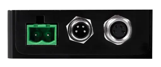
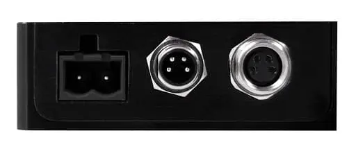
Aside from this physical difference, the version setting is the most reliable way to identify the exact firmware version.
When will each product family be upgraded to 7.xx?
This schedule covers devices that were initially firmware 6.xx. There are new product families that were introduced with firmware 7.xx, and they are not covered in this list.
| Family | Estimated Date |
|---|---|
| X-LHM, X-LHM-E | Completed (May 2019) |
| X-VSR | Completed (May 2019) |
| X-NA, X-NA-E | Completed (May 2019) |
| X-RSB, X-RSB-E | Completed (May 2019) |
| X-GSM, X-GSM-E | Completed (June 2019) |
| X-GSM-SV | Completed (June 2019) |
| X-LRM, X-LRM-E | Completed (June 2019) |
| X-LRM-DE | Completed (June 2019) |
| X-LSM, X-LSM-E | Completed (June 2019) |
| X-LSM-SV | Completed (June 2019) |
| X-LRQ-SV | Completed (June 2019) |
| X-RSM, X-RSM-E | Completed (June 2019) |
| X-RSM-SV | Completed (June 2019) |
| X-RST, X-RST-E | Completed (June 2019) |
| X-RST-DE | Completed (June 2019) |
| X-RSW, X-RSW-E | Completed (February 2020) |
| Family | Estimated Date |
|---|---|
| X-RSW-SV | Completed (June 2019) |
| X-VSR-SV | Completed (June 2019) |
| X-LRT, X-LRT-E | Completed (June 2019) |
| X-BLQ-E | Completed (March 2020) |
| X-LRQ-DE | Completed (November 2019) |
| X-LRQ-E | Completed (November 2019) |
| X-LSQ, X-LSQ-E | Completed (May 2020) |
| X-NMS, X-NMS-E | Completed (November 2019) |
| X-DMQ-AE | Completed (December 2020) |
| X-GLP-E | Contact Us |
| X-FWR-E | Completed (January 2021) |
| X-MCA | Completed (July 2020) |
| X-MCB1 | Completed (June 2020) |
| X-MCB2 | Completed (June 2020) |
| X-JOY | Not planned |
What should I do if I'd like to upgrade to firmware 7.xx?
Because the new firmware version requires a hardware update, devices with firmware 6.xx would need to be returned to Zaber to have the controller replaced in order to use firmware 7.xx. If you're interested in this, email contact@zaber.com with the serial number(s) of the device(s) you'd like to upgrade for a quotation and return instructions.
What are the firmware changes from 6.xx to 7.xx?
Generally, firmware 7.xx was designed to be as backwards-compatible with firmware 6.xx as possible. In order to introduce new features and make improvements, some notable differences were introduced. Find below a reference for all of the changes made. The list will generally refer to the Zaber ASCII protocol, and sections specific to the Zaber Binary protocol will be noted. New functionality, commands, and settings will continue to be released in firmware 7.xx over time, and these differences will not be reflected here.
Deprecated Commands and Settings
In a number of cases, a new command or setting has been introduced that replaces the function of a firmware 6.xx command or setting. These new commands and settings are recommended, but the firmware 6.xx commands and settings will continue to function. However, they are considered deprecated, and will no longer be publicly documented (aside from here) and will not be further developed.
| Deprecated | Recommended Replacement | Notes | |
|---|---|---|---|
| Commands | Commands | ||
| lockstep info | lockstep print and lockstep get | ||
| stream io toggle do | stream io set do | The 't' parameter has been added to this command to instruct that the output should be toggled. | |
| Notes: The 't' parameter has been added to this command to instruct that the output should be toggled. | |||
| tools parking state | parking.state setting | ||
| trigger info | trigger.numtriggers and trigger.numactions settings | In FW7, time and distance triggers are not a separate type of trigger. Both time and distance can now be used as conditions in general-purpose triggers.Therefore, there is no need to return specifically how many time triggers or how many distance triggers there are. | |
| Notes: In FW7, time and distance triggers are not a separate type of trigger. Both time and distance can now be used as conditions in general-purpose triggers.Therefore, there is no need to return specifically how many time triggers or how many distance triggers there are. | |||
| trigger time | trigger | In FW7, time and distance triggers are not a separate type of trigger. | |
| Notes: In FW7, time and distance triggers are not a separate type of trigger. | |||
| trigger dist | trigger | In FW7, time and distance triggers are not a separate type of trigger. | |
| Notes: In FW7, time and distance triggers are not a separate type of trigger. | |||
| trigger action io do | trigger action io set do | Matches the normal IO command set. | |
| Notes: Matches the normal IO command set. | |||
| io get di/do/ai/ao | io get di/do/ai/ao port | ||
| Settings | Settings | ||
| limit.swapinputs | none | Not recommended to use, especially on calibrated devices. | |
| Notes: Not recommended to use, especially on calibrated devices. | |||
| comm.rs232.protocol | comm.protocol | ||
| comm.usb.protocol | comm.protocol | ||
| estop | none | A new emergency stop command will be introduced in the future. | |
| Notes: A new emergency stop command will be introduced in the future. | |||
| cloop.mode | cloop.enable and cloop.recovery.enable | Some values of cloop.mode are now rejected: 1, 2, 4. See Encoder Feedback and Closed-Loop section for more information. | |
| Notes: Some values of cloop.mode are now rejected: 1, 2, 4. See Encoder Feedback and Closed-Loop section for more information. | |||
| deviceid | device.id | ||
| peripheralid | peripheral.id | ||
| limit.away.pos | limit.max | ||
| limit.home.pos | limit.min | ||
| encoder.error | encoder.pos.error | ||
| cloop.counts | encoder.ratio.div | ||
| cloop.steps | encoder.ratio.mult | ||
| cloop.stalltimeout | cloop.timeout | ||
| encoder.count.calibrated | encoder.count.cal | ||
| Binary | Binary | ||
| Set Device Mode (Cmd 40) | Set Auto-Reply Disabled Mode (Cmd 101) Set Message ID Mode (Cmd 102) Set Home Sensor Type (Cmd 104) Set Home Status (Cmd 103) Set Auto-Home Disabled Mode (Cmd 105) Set Knob Disabled Mode (Cmd 107) Set Knob Direction (Cmd 108) Set Move Tracking Mode (Cmd 115) Set Manual Move Tracking Disabled Mode (Cmd 116) | ||
No Longer Supported Commands and Settings
In rare cases, firmware 6.xx commands or settings had to be discontinued with no current replacement in firmware 7.xx. While we don't expect any of these to be a problem, email contact@zaber.com if you have any concerns.
| Command/Setting | Recommended Replacement | Notes | |
|---|---|---|---|
| Commands | Commands | ||
| reg | This was a hidden command to be able to directly edit memory registers; it is no longer supported. | ||
| Notes: This was a hidden command to be able to directly edit memory registers; it is no longer supported. | |||
| help | |||
| Settings | Settings | ||
| cloop.duration.max | cloop.settle.period | ||
| lockstep.tolerance | lockstep get|set tolerance | This new command requires that the lockstep group is enabled before it can be read or changed. | |
| Notes: This new command requires that the lockstep group is enabled before it can be read or changed. | |||
| encoder.index.count | |||
| encoder.index.phase | |||
| system.current | No firmware 7.xx controllers support reading the current draw. | ||
| Notes: No firmware 7.xx controllers support reading the current draw. | |||
| comm.rs485.baud comm.rs485.enable comm.rs485.protocol | No firmware 7.xx controllers support RS485 communication. | ||
| Notes: No firmware 7.xx controllers support RS485 communication. | |||
| Binary | Binary | ||
| Read Register (Cmd 5) | |||
| Set Active Register (Cmd 6) | |||
| Write Register (Cmd 7) | |||
Motion Trajectory
These changes relate to how the motion trajectory is planned, or to the available movement commands.
| Firmware 6.xx Behaviour | Firmware 7.xx Behaviour |
|---|---|
| The data value of a tools storepos command was 0. | The data value of a tools storepos command is the position(s) being stored. |
| If action 3 was used for a tools gotolimit command, it behaved as if action 2 were used. | If action 3 is used for a tools gotolimit command, the command is rejected. |
| The maximum valid value for any velocity or speed was 2147483647. | The maximum valid value for any velocity or speed is 68719476704. |
| The maximum valid value for any acceleration was 32767. | The maximum valid value for any acceleration is 2147483647. |
| On some devices, the tools gotolimit command could reverse directions to continue searching for a sensor if a device stalled when moving in the requested direction. | The tools gotolimit command will only move in the requested direction. If a device stalls, it will abandon the search for a sensor. |
| The tools storepos command would reject values that were outside of the devices range of motion. | The tools storepos does not reject values, because it's possible for the valid range of the device to change. Instead, the validity of the position is evaluated when the move stored command is used. |
| The WR warning flag would not be set if driver.dir or encoder.dir were changed. The pos and encoder.count values would not change. | The WR warning flag is set when driver.dir or encoder.dir are changed. The pos is not updated, but the encoder.count is reset to 0. |
Driver
These changes relate to the motor driver.
| Firmware 6.xx Behaviour | Firmware 7.xx Behaviour |
|---|---|
| There was no way to directly disable the driver, and the driver being disabled was not latching (it would re-enable when the condition that caused it to disable was no longer present). | The driver can be disabled using the driver disable command. Motion commands will be rejected with the reason DRIVERDISABLED if the driver is disabled. The user must enable the driver first with the driver enable command. |
| The maximum value of the run current (driver.current.run) and hold current (driver.current.hold) were only limited to driver's maximum current output (driver.current.max). | In addition to being limited by the driver's maximum output current (driver.current.max), the maximum value of the run current (driver.current.run) is limited by the RMS value of the motor's rated current (motor.current.max) and the maximum value of the hold current (driver.current.hold) is limited by the peak value of the motor's rated current (motor.current.max / √2). This helps ensure that the motor is not supplied with an unsafe current. |
Encoder Feedback and Closed-Loop
These changes relate to how encoder feedback, either motor-encoder or direct-encoder, is used to inform and improve the motion.
| Firmware 6.xx Behaviour | Firmware 7.xx Behaviour | |||||||||||||||||||||
|---|---|---|---|---|---|---|---|---|---|---|---|---|---|---|---|---|---|---|---|---|---|---|
| The encoder.count setting could be set (with advanced access). The value of encoder.count would reset to 0 after homing, and could change if the cloop.counts or cloop.steps settings were changed. | The encoder.count setting is read-only, and the value can only change based on encoder feedback. It represents a running count since powering on. The exception to this is if the driver.dir or encoder.dir settings are set. | |||||||||||||||||||||
| An axis with a direct encoder would become IDLE when the measured position was within a specific tolerance of the target for a specific duration. After a timeout period, the axis would become IDLE regardless of whether that tolerance had been reached. | An axis with a direct encoder becomes IDLE when the measured position is within a specific tolerance (cloop.settle.tolerance) for a specific duration (cloop.settle.period). There is no time limit for this to be achieved. | |||||||||||||||||||||
| A single setting, cloop.mode, controlled multiple aspects of how encoder feedback was used. Different values, from 0 to 5, represented different combinations of behaviour (varying based on the type of motor and the type of encoder). | Each aspect of how encoder feedback is used is controlled by a separate setting. The cloop.enable and cloop.recovery.enable settings control the same behaviour that cloop.mode did, although some behaviour is no longer supported. Here is a table showing the mapping:
| |||||||||||||||||||||
| An axis with a direct encoder would adjust the value of pos by 4 steps if a motor slip was detected in order to ensure no steps were missed. | An axis with a direct encoder does not update the value of pos if a motor slips, and instead tries to catch up to the expected position. | |||||||||||||||||||||
| Axes with both stepper motors and direct encoders used open-loop control during movement, and then applied a correction based on the encoder at the end position. | Axes with both stepper motors and direct encoders use a feedback loop (specifically a simple Proportional-Integral controller) during movements for continuous correction. This allows commands such as move sin and stream to work with these devices. The axis can continue using this controller for correction when IDLE by setting cloop.continuous.enable to 1, but it has a side effect of making any axis back-driveable when powered. | |||||||||||||||||||||
| When displacement recovery is enabled, the WM warning flag is set when the axis is displaced, and WM, NI, and NC are cleared when the recovery begins (after the axis has settled). | The WM warning flag is set when the axis is displaced for the stall timeout duration. No warning flags are cleared when displacement recovery begins. This means that WM ends up set, rather than cleared, after the recovery finishes. | |||||||||||||||||||||
| When enabling closed-loop mode (using cloop.mode), the value of encoder.pos was adjusted to match pos. | When enabling closed-loop mode (using cloop.enable), the value of pos is adjusted to match encoder.pos. | |||||||||||||||||||||
Triggers
These changes relate to the trigger command.
| Firmware 6.xx Behaviour | Firmware 7.xx Behaviour |
|---|---|
| The unit for triggering on an analog input condition was 0.1 mV (e.g. /trigger 1 when io ai < 5000 created a trigger with a condition of analog input 1 being below 0.5 V). | The unit for triggering on an analog input condition is volts (e.g. /trigger 1 when io ai < 0.5 creates a trigger with a condition of analog input 1 being below 0.5 V). |
| There was no way to determine what the condition or action of a trigger was. | The condition and action of a trigger can be read using the trigger print command. |
| A setting could be decremented by incrementing a negative value (e.g. /1 trigger 3 action b 1 maxspeed += -10000). | While a negative value can still be used when incrementing a setting, a decrement operator is also available (e.g. /1 trigger 3 action b 1 maxspeed -= 10000) |
| The axis number was required to be specified in trigger conditions and actions that referred to settings. | The axis number can be omitted when configuring a trigger condition or action that refers to a setting if it is unambiguous what axis it relates to. For trigger actions, this would usually mean all axes would be set if no axis is included. For trigger conditions, it is ambiguous if the setting is an axis specific one on a multi-axis controller, and no axis is specified. |
IO
These changes relate to the digital and analog inputs and outputs on devices where they are available.
| Firmware 6.xx Behaviour | Firmware 7.xx Behaviour |
|---|---|
| The valid values when setting a digital output were 1 (high) and 0 (low). | The valid values when setting a digital output are 1 (high), 0 (low), t (toggle the value), and k (keep the current value). These can be used when setting an individual digital output, or setting the entire port. |
Streams
| Firmware 6.xx Behaviour | Firmware 7.xx Behaviour |
|---|---|
| The unit for waiting on an analog input was 0.1 mV (e.g. /stream 1 wait io ai < 5000 would pause a stream until analog input 1 was below 0.5 V). | The unit for waiting on an analog input is volts (e.g. /stream 1 wait io ai < 0.5 will pause a stream until analog input 1 is below 0.5 V). |
Lockstep
| Firmware 6.xx Behaviour | Firmware 7.xx Behaviour |
|---|---|
| The default twist tolerance of a lockstep group was 0, and needed to be explicitly set in order to enforce a limitation. | A reasonable value is set as the default for the twist tolerance when a lockstep group is enabled. |
| To park or unpark a lockstep group, the tools parking command could be used. | To park or unpark a lockstep group, the lockstep park|upark command should be used. The tools parking command will be rejected if used on a device or axis that has a lockstep group. |
| If comm.alert was enabled, a single alert message was sent from the primary axis of a lockstep group at the completion of a motion. | If comm.alert is enabled, an alert message is sent for each axis in a lockstep group at the completion of a motion. |
| Changing the peripheralid setting of an axis in a lockstep group would not disable the lockstep group. | Changing the peripheral.id setting of an axis in a lockstep group will disable the lockstep group. |
| Enabling or disabling a lockstep group would not clear the NI warning flag. | Enabling or disabling a lockstep group will clear the NI warning flag. |
Controllers and Peripherals
| Firmware 6.xx Behaviour | Firmware 7.xx Behaviour |
|---|---|
| Controllers would not recognize when a peripheral with Auto Detect was plugged in. Setting the peripheralid to the number corresponding to the model was required to configure default settings. | Controllers recognize when a peripheral with Auto Detect is plugged in, but can still work with non-Auto-Detect peripherals by setting the peripheral.id to the number corresponding to the model. |
| Controllers would not recognize when a peripheral was unplugged. | Controllers always recognize when a peripheral with Auto Detect is unplugged, and may recognize when a non-Auto-Detect peripheral is unplugged. The driver will be deactivated in these cases, and a command may need to be sent to re-activate for non-Auto-Detect peripherals after they are plugged in. |
| Controllers shipped with a peripheralid of 0, which represented 'Safe Mode'. This mode supplied low current to any connected motors by default, in an effort to avoid overheating them. | Controllers ship with a peripheral.id of 0, which represents 'Unused' mode. In this mode, commands to drive the axis will be rejected, although motion commands sent to the device level will ignore this axis. If an Auto-Detect peripheral is plugged in when in 'Unused' mode, the axis will automatically activate. |
| The peripheral.serial setting was writable, and was used to help match calibration settings with axes. | The peripheral.serial setting is read-only, and is stored (along with calibration data) on the Auto Detect memory of a peripheral. Peripherals without Auto Detect will have a peripheral.serial of 0, and calibration data is set on the axis level rather than the device level. |
Parking
These changes relate to the tools parking function.
| Firmware 6.xx Behaviour | Firmware 7.xx Behaviour |
|---|---|
| The tools parking command was a device-scope command. This means that on a device with two axes, the axes could not be individually parked. | The tools parking command is an axis-scope command. The axes of a two-axis device can be individually parked. If using the tools parking state command, a value of 0 will be returned if all axes are unparked, a value of 1 will be returned if both axes are parked, and a value of 2 will be returned if one of the two axes are parked. Use the parking.state setting to determine which of the axes are parked. |
| Parking a device would disable the driver. There would be no power to the motor after parking. | Parking a device does not disable the driver. A motor will continue to be powered after parking. Use the driver disable and driver enable commands to control the driver instead. |
Binary
These changes are specific to the Zaber Binary Protocol.
| Firmware 6.xx Behaviour | Firmware 7.xx Behaviour |
|---|---|
| The Return Status (Cmd 54) command would return a number of different potential conditions or states. | The Return Status (Cmd 54) command will return only 4 states: 0 (Idle), 65 (Parked), 90 (Driver Disabled), or 99 (Busy). |
| On a multi-axis controller, the Message ID Mode (Cmd 102) setting could be set to different values for each axis. | On a multi-axis controller, the Message ID Mode (Cmd 102) setting must be the same for all axes. Changing this setting for one axis will also adjust the other axis. |
| The Manual Move Tracking Disabled Mode (Cmd 116) setting could be adjusted on devices that do not have knobs. | The Manual Move Tracking Disabled Mode (Cmd 116) setting is not available on devices that do not have knobs. |
| Changing the Device Direction (Cmd 121) setting would set both the driver direction and encoder direction based on the input data (0 for default, 1 to invert). | If the value of the Set Device Direction (Cmd 121) setting is changed, the encoder direction will also toggle. Use the ASCII setting encoder.dir to set the encoder direction independently from the driver direction. |
| The name of Cmd 38 was Set Running Current. | The name of Cmd 38 is Set Run Current, to be more consistent with common drive terminology. |
| The encoder count could be read with Return Encoder Count (Cmd 82). The value of the encoder count would reset to 0 after homing | The encoder count represents a running count since powering on. The exception to this is if the value of the Set Device Direction (Cmd 121) setting is changed. In addition to Return Encoder Count (Cmd 82), the command Return Encoder Position (Cmd 89) is available to read the encoder value in the same reference frame and units as Return Current Position (Cmd 60). |
| Slip Tracking (Cmd 12) and Unexpected Position (Cmd 13) responses included the Current Position (Cmd 60) value. | Slip Tracking (Cmd 12) and Unexpected Position (Cmd 13) responses include the Encoder Position (Cmd 89) value. |
| During commanded movement, a number of commands and settings would be rejected. For example, Set Maximum Position (Cmd 44) would be rejected during motion. | During commanded movement, more commands and settings are accepted. For example, Set Maximum Position (Cmd 44) is accepted during motion. Some commands and settings are still rejected, including knob movements, Set Microstep Resolution (Cmd 37), Set Park State (Cmd 65), and Set Peripheral ID (Cmd 66). |
| The Stop (Cmd 23) and Set Microstep Resolution (Cmd 37) commands could be used while a device is parked, causing the device to become unparked. The Set Peripheral ID (Cmd 66) command could be sent while parked. | The Stop (Cmd 23) and Set Microstep Resolution (Cmd 37) commands are rejected while a device is parked. The Set Peripheral ID (Cmd 66) command can not be sent while parked. |