Scope
This manual defines Zaber’s Binary protocol for all products with firmware versions 7.60 and below. Not all commands or settings are supported by all products. See the product-specific protocol manual for which commands and settings a product supports.
This manual defines Zaber’s Binary protocol and the device settings and commands for the GENERIC PRODUCT running firmware version 7.60. Other products or firmware versions may support other commands or settings; see a product’s specific protocol manual for the commands and settings it supports.
If your device uses Firmware 6, refer to the Firmware 6 Binary Protocol Manual. See here for instructions on how to tell which version your device uses.
The Binary protocol has limited features and is supported only on certain products for backwards compatibility. It has been replaced with Zaber’s ASCII protocol, which is actively developed, more robust, and full-featured.
Conventions
Conventions used throughout this document:
- For clarity, each binary message is presented as an array of its fields,
[n, c, d], where:nis the device number,cis the command number, anddis the command-specific data.
- A binary message sent from the host to a device is indicated with a
→suffix (e.g.,[0, 1, 0] →). - A binary message sent from the device to the host is indicated with a
←prefix (e.g.,← [0, 1, 0]).
Physical Units
Many of the setting values and command parameters described in this document relate to physical units, such as distance, voltage, and time. When a setting value is expressed in a real-world metric unit or in a scaled version of a unit, the units are described explicitly (such as a voltage specified in units of volts, or a current specified in 20 mA increments). In other cases, the value is unitless and some scaling factor is required to convert to a practical unit. Unitless values may be referred to in this document as the ‘data’ value.
In general, the documentation of each command or setting describes how to convert the relevant data values to real-world units. An exception is for values involving physical distances or positions (including speed/velocity and acceleration/deceleration), which are described here. This section is referenced whenever they’re used in a command or setting.
Converting data values involving distance or position to real-world values requires a device-specific conversion factor, which is listed in the "Specifications" section of the device’s User Manual.
For stepper motors, this conversion factor is called "Microstep Size". The value in the User Manual assumes the Microstep Resolution is at the default value. If you have modified the resolution value, the Microstep Size can be converted:
The default resolution is available at Zaber Support - Device Settings.
For direct-drive motor products, this conversion factor is called "Encoder Count Size".
Position
For stepper motor products, all position and distance data values are in units of stepper motor microsteps. The conversion from distance or position data values to real-world units is given by:
For direct-drive motor products, all position and distance data values are in units of encoder counts. The conversion from distance or position data values to real-world units is given by:
Velocity
For stepper motor products, the conversion from velocity or speed data values to real-world units is given by:
For direct-drive motor products, the conversion from velocity or speed data values to real-world units is given by:
Acceleration
For stepper motor products, the conversion from acceleration or deceleration data values to real-world units is given by:
For direct-drive motor products, the conversion from acceleration or deceleration data values to real-world units is given by:
Quick Start
Connecting
Zaber devices support connecting to user equipment over standard serial connections using Zaber’s Binary protocol. The fastest way to set up Zaber devices with the Binary protocol is to use Zaber Console.
Zaber devices typically communicate over RS-232 at 9600 baud, with 8 bits, 1 stop bit and no parity. However, please refer to the RS-232 Communications section of the device-specific User Manual for supported settings.
Talking to Zaber Devices
Zaber devices listen for commands sent to them over a serial port and respond after completing the command. All binary messages share the same Message Format and encode:
- the device number
- the command number
- the command-specific data
  [1, 20, 10000] →  // Request to device 1, Move Absolute, Position 10000
← [1, 20, 10000]    // Response from device 1, Move Absolute, Position 10000
                    // (device stopped at final position)
To send the same message to all devices in a chain, use device number 0. Each device will send its own response after completing the command:
  [0, 20, 10000] →  // Request to all devices, Move Absolute, Position 10000
← [1, 20, 10000]    // Response from device 1, Move Absolute, Position 10000
← [3, 20, 10000]    // Response from device 3, Move Absolute, Position 10000
← [2, 20, 10000] // Response from device 2, Move Absolute, Position 10000Making it Move
After connecting and powering the device, send the Home (Cmd 1) command. The device will move to the home limit sensor and establish a reference position:
  [0, 1, 0] →  // Request to all devices, Home
← [1, 1, 0]    // Response from device 1, Home, Position 0
If the device hasn’t been homed, motion commands may not work as expected. The controller’s position limits will not match the physical limits, absolute movements will not move to expected positions, and relative movements the device is capable of may be rejected for being outside the travel range.
Once the device has been homed, make the device move by sending a Move Relative (Cmd 21) command. For example, to move a distance of 10,000 forward from the current position:
// Device 1 at position 555
  [0, 21, 10000] →  // Request to all devices, Move Relative, Distance 10000
← [1, 21, 10555]    // Response from device 1, Move Relative, Position 10555
To move to the absolute position 10,000, measured from the home position, regardless of the current position, send a Move Absolute (Cmd 20) command:
// Device 1 at position 555
  [0, 20, 10000] →  // Request to all devices, Move Absolute, Position 10000
← [1, 20, 10000]    // Response from device 1, Move Absolute, Position 10000
See the Physical Units section for information about unit conversions.
Using Device Settings
Use the set commands to configure the device. For example, to set the target speed to 10,000:
  [0, 42, 10000] →  // Request to all devices, Set Target Speed, Speed 10000
← [1, 42, 10000]    // Response from device 1, Set Target Speed, Speed 10000
The target speed is now set to 10,000.
To read the value of a setting use the Return Setting (Cmd 53) command:
  [0, 53,    42] →  // Request to all devices, Return Setting, Set Target Speed
← [1, 42, 10000]    // Response from device 1, Set Target Speed, Speed 10000
The current target speed is 10,000.
Read-only settings (as well as a few writable settings) have a return command for reading their value. For example, to read the device status:
  [0, 54,  0] →  // Request to all devices, Return Status
← [1, 54, 99]    // Response from device 1, Return Status, Device busy
For convenience, return commands can also be passed as data to Return Setting (Cmd 53):
  [0, 53, 54] →  // Request to all devices, Return Setting, Return Status
← [1, 54, 99]    // Response from device 1, Return Status, Device busy
Message Format
All Binary messages consist of six bytes. They must be transmitted with less than 10 milliseconds between each byte. If the device has received less than six bytes and a period longer than 10 milliseconds passes, it will assume the remaining data has been lost and will discard the previously received bytes. We recommend that customer software behave similarly when receiving data from devices, especially in electrically noisy environments.
The six bytes are ordered as follows:
- Device number
- Command number
- Data, least significant byte (LSB)
- Data
- Data
- Data, most significant byte (MSB)
The first byte is the device number in the daisy-chain. Generally, device number 1 is the closest device to the computer, device 2 is next, and so on (see Renumber (Cmd 2) to sequentially number devices in the chain). If the number 0 is used, the command will be directed to all devices in the chain. Each axis of a multi-axis device appears as a separate device with its own device number.
The second byte is the command number. Bytes 3, 4, 5, and 6 can be combined to form a signed 32-bit data value, with the least significant byte transmitted first (see Appendix B: Message Data Conversion Algorithm for more details). Each command interprets the data value differently.
There are four types of commands:
- Action commands
-
Commands that cause the device to perform an action (e.g., move). See Action Command Reference for a list of all action commands.
- Set commands
-
Commands that set the value of a setting. See Set Command Reference for a list of all set commands.
- Return commands
-
Commands that return a setting’s value. See Return Command Reference for a list of all return commands.
- Reply-Only commands
-
Messages that are only ever sent from the device to the user. Most are spontaneously sent by the device and are not in response to a user command. See Reply-Only Command Reference for a list of all reply-only commands.
Most commands elicit a reply message in the same six-byte format, with a few minor differences. The first byte in the reply is the number of the device that just finished executing the command, not the device number the original message was sent to. For instance, a message addressed to 0 (i.e., all devices) will elicit a reply from each device in the daisy-chain. The second byte is either the number of the command that the device just executed or 255 (0xFF) if an error occurs (see Error (Cmd 255) for more information on errors).
If desired, byte 6 can be repurposed as a message ID (in place of a byte of data). See Message ID Mode for more information.
Example: How to encode binary commands
Various commands and their byte encoding according to the Binary message format are shown below.
| Command Description | Device | Command | Data (LSB → MSB) | |||
|---|---|---|---|---|---|---|
| Request to all devices, Home (Cmd 1) | 0 | 1 | 0 | 0 | 0 | 0 |
| Request to all devices, Renumber (Cmd 2) | 0 | 2 | 0 | 0 | 0 | 0 |
| Request to all devices, Return Firmware Version (Cmd 51) | 0 | 51 | 0 | 0 | 0 | 0 |
| Request to device 1, Move Absolute (Cmd 20) to position 257 | 1 | 20 | 1 | 1 | 0 | 0 |
| Request to device 2, Move Relative (Cmd 21) a distance of -1 | 2 | 21 | 255 | 255 | 255 | 255 |
Quick Command Reference
| Name | Command | Data | Type | Reply Data |
|---|---|---|---|---|
| Reset | 0 | Ignored | Action | None |
| Home | 1 | Ignored | Action | Current position |
| Renumber | 2 | Device number | Action | Device ID |
| Move Tracking | 8 | Ignored | Reply-only | Current position |
| Limit Active | 9 | Ignored | Reply-only | Current position |
| Manual Move Tracking | 10 | Ignored | Reply-only | Current position |
| Manual Move | 11 | Ignored | Reply-only | Current position |
| Slip Tracking | 12 | Ignored | Reply-only | Encoder position |
| Unexpected Position | 13 | Ignored | Reply-only | Encoder position |
| Store Current Position | 16 | Number | Action | Number |
| Return Stored Position | 17 | Number | Action | Stored position |
| Move To Stored Position | 18 | Number | Action | Current position |
| Move Absolute | 20 | Absolute position | Action | Current position |
| Move Relative | 21 | Distance | Action | Current position |
| Move at Constant Speed | 22 | Velocity | Action | Velocity |
| Stop | 23 | Ignored | Action | Current position |
| Restore Settings | 36 | 0 or peripheral ID | Action | 0 or peripheral ID |
| Set Microstep Resolution | 37 | Number of microsteps | Set | Number of microsteps |
| Set Run Current | 38 | Run current | Set | Run current |
| Set Hold Current | 39 | Hold current | Set | Hold current |
| Set Home Speed | 41 | Speed | Set | Speed |
| Set Target Speed | 42 | Speed | Set | Speed |
| Set Acceleration | 43 | Acceleration | Set | Acceleration |
| Set Maximum Position | 44 | Position | Set | Position |
| Set Current Position | 45 | Position | Set | Position |
| Set Home Offset | 47 | Offset | Set | Offset |
| Set Alias Number | 48 | Alias number | Set | Alias number |
| Return Device ID | 50 | Ignored | Return | Device ID |
| Return Firmware Version | 51 | Ignored | Return | Version |
| Return Power Supply Voltage | 52 | Ignored | Return | Voltage |
| Return Setting | 53 | Setting to return | Action | Setting value |
| Return Status | 54 | Ignored | Return | Status |
| Echo Data | 55 | Data | Action | Data |
| Return Firmware Build | 56 | Ignored | Return | Build number |
| Return Current Position | 60 | Ignored | Return | Position |
| Return Serial Number | 63 | Ignored | Return | Serial number |
| Set Park State | 65 | Park state | Set | Park state |
| Set Peripheral ID | 66 | Peripheral ID | Set | Peripheral ID |
| Return Digital Input Count | 67 | Ignored | Return | Digital input channel count |
| Read Digital Input | 68 | Channel number | Action | Channel state |
| Read All Digital Inputs | 69 | Ignored | Action | Channel states |
| Return Digital Output Count | 70 | Ignored | Return | Digital output channel count |
| Read Digital Output | 71 | Channel number | Action | Channel state |
| Read All Digital Outputs | 72 | Ignored | Action | Channel states |
| Write Digital Output | 73 | Channel state | Action | Channel state |
| Write All Digital Outputs | 74 | Channel states | Action | Channel states |
| Return Analog Input Count | 75 | Ignored | Return | Analog input channel count |
| Read Analog Input | 76 | Channel number | Action | Channel voltage |
| Move Index | 78 | Index number, which must be positive | Action | Current position |
| Set Index Distance | 79 | Distance | Set | Distance |
| Set Cycle Distance | 80 | Distance | Set | Distance |
| Set Filter Holder ID | 81 | Holder ID | Set | Filter holder ID |
| Return Encoder Count | 82 | Ignored | Return | Encoder count |
| Return Calibrated Encoder Count | 83 | Ignored | Return | Calibrated encoder count |
| Return Calibration Type | 84 | Ignored | Return | Calibration type |
| Return Calibration Error | 85 | Ignored | Return | Calibration error |
| Return Peripheral Serial Number | 86 | Ignored | Return | Peripheral serial number |
| Return Encoder Position | 89 | Ignored | Return | Encoder position in distance units |
| Return Pending Peripheral ID | 91 | Ignored | Return | Peripheral ID |
| Return Pending Peripheral Serial Number | 92 | Ignored | Return | Peripheral serial number |
| Activate | 93 | Ignored | Action | None |
| Set Auto-Reply Disabled Mode | 101 | Auto-reply disabled mode | Set | Auto-reply disabled mode |
| Set Message ID Mode | 102 | Message ID mode | Set | Message ID mode |
| Set Home Status | 103 | Home status | Set | Home status |
| Set Auto-Home Disabled Mode | 105 | Auto-home disabled mode | Set | Auto-home disabled mode |
| Set Minimum Position | 106 | Position | Set | Position |
| Set Knob Disabled Mode | 107 | Knob disabled mode | Set | Knob disabled mode |
| Set Knob Direction | 108 | Knob direction | Set | Knob direction |
| Set Knob Movement Mode | 109 | Knob movement mode | Set | Knob movement mode |
| Set Knob Jog Size | 110 | Distance | Set | Distance |
| Set Knob Velocity Scale | 111 | Speed | Set | Speed |
| Set Knob Velocity Profile | 112 | Interpolation | Set | Interpolation |
| Set Acceleration Only | 113 | Acceleration | Set | Acceleration |
| Set Deceleration Only | 114 | Deceleration | Set | Deceleration |
| Set Move Tracking Mode | 115 | Move tracking mode | Set | Move tracking mode |
| Set Manual Move Tracking Disabled Mode | 116 | Manual move tracking disabled mode | Set | Manual move tracking disabled mode |
| Set Move Tracking Period | 117 | Move tracking period (ms) | Set | Move tracking period (ms) |
| Set Closed-Loop Mode | 118 | Closed-loop mode | Set | Closed-loop mode |
| Set Slip Tracking Period | 119 | Slip tracking period (ms) | Set | Slip tracking period (ms) |
| Set Stall Timeout | 120 | Stall timeout | Set | Stall timeout |
| Set Baud Rate | 122 | Baud rate | Set | Baud rate |
| Set Protocol | 123 | Protocol | Set | Protocol |
| Convert to ASCII | 124 | Baud rate | Action | Baud rate |
| Error | 255 | Ignored | Reply-only | Error code |
Action Command Reference
The following section details Binary action commands. Use these commands to perform an action or task (e.g., move the device, restore settings, etc.).
Reset (Cmd 0)
Resets the device to the power-up state
- Data
- Ignored
- Reply Data
- None
This command resets the device to the power-up state. After receiving this command, the device waits until no other chained devices have communicated for 200 ms before performing the reset. Any commands sent to the device during this 200 ms period are discarded with no reply sent. The device does not reply to this command.
Example: Resetting the device
[1, 0, 0] →  // Request to device 1, Reset
             // No response from device 1
Home (Cmd 1)
Moves the device to the home position
- Data
- Ignored
- Reply Data
- Current position
Moves the device towards the home position at the Home Speed until the home sensor is triggered. Once the home position is reached, the current position is reset (to 0 for most devices), establishing the reference position. If a Home Offset has been specified, the device will move forward the specified offset before resetting the position.
Error Codes
This command may return the following error codes:
- 1
-
Cannot Home
The device has travelled a long distance without triggering the home sensor. It may be stalling or slipping.
- 6501
-
Device Parked
The device is currently parked. Use Park State or Home (Cmd 1) to unpark the device before requesting a move.
- 9001
-
Driver Disabled
The device has disabled the driver due to an overheating or over-current condition, or because the driver voltage is outside the normal operating range. The device cannot move. To re-enable the driver, send the Reset (Cmd 0) command.
- 9301
-
Peripheral Inactive
The axis is inactive. See Appendix C: Configuring and Activating Peripherals for more information about activating peripherals.
See also Error (Cmd 255)
Renumber (Cmd 2)
Updates the device number of one or more devices
- Data
-
Device number
1 to 254
- Reply Data
Device ID
When this command is sent to all devices in a daisy-chain, it sequentially sets the device number of each device. The device closest to the computer is given device number 1. The remaining devices in the daisy-chain are numbered consecutively.
When Renumber (Cmd 2) is sent to a specific device number, it sets the device number to the specified value on that device only.
Error Codes
This command may return the following error codes:
- 2
-
Device Number Invalid
The requested device number is out of range.
See also Error (Cmd 255)
Example: Renumbering all devices in a chain
  [0, 2,     0] →  // Request to all devices, Renumber, Device number 0
← [1, 2, 50000]    // Response from device 1, Renumber, Device ID 50000
← [2, 2, 30211]    // Response from device 2, Renumber, Device ID 30211
The devices are renumbered, with the device closest to the computer having device number 1, and the next closest having device number 2.
Example: Renumbering a specific device
Renumber device 2 to 4:
  [2, 2,     4] →  // Request to device 2, Renumber, Device number 4
← [4, 2, 50000]    // Response from device 4, Renumber, Device ID 50000
Store Current Position (Cmd 16)
Stores the current position
- Data
-
Number
0 to 15
- Reply Data
- Number
Saves the current position into the stored position specified by <number>. A total of 16 positions (numbered 0 to 15) can be stored. Stored positions are non-volatile and persist after a power-up or system reset. This command can only be executed after the device has been homed.
See also Move To Stored Position (Cmd 18) and Return Stored Position (Cmd 17).
Error Codes
This command may return the following error codes:
- 1600
-
Save Position Invalid
The requested stored position index is out of range.
- 1601
-
Save Position Not Homed
Store Current Position is not allowed until the device has been homed.
See also Error (Cmd 255)
Return Stored Position (Cmd 17)
Returns a stored position
- Data
-
Number
0 to 15
- Reply Data
- Stored position
Returns a position previously stored by a Store Current Position (Cmd 16) command. The data specifies which stored position to return.
See also Move To Stored Position (Cmd 18).
See the Physical Units section for information about unit conversions.
Error Codes
This command may return the following error codes:
- 1700
-
Return Position Invalid
The requested stored position index is out of range.
See also Error (Cmd 255)
Move To Stored Position (Cmd 18)
Moves to a stored position
- Data
-
Number
0 to 15
- Reply Data
- Current position
Moves the axis to the stored position specified by the number in the data value. Each stored position defaults to position 0 until another position is saved to it, so moving to a stored position that has not been set will move the axis to position 0. This command can only be executed after the device has been homed.
To store a position, use Store Current Position (Cmd 16). To read the value of a stored position, use Return Stored Position (Cmd 17).
Error Codes
This command may return the following error codes:
- 18
-
Stored Position Invalid
The position stored in the requested register is no longer valid. This is probably because the maximum range was reduced.
- 1800
-
Move Position Invalid
The requested stored position is out of range.
- 1801
-
Move Position Not Homed
Move to Stored Position is not allowed until the device has been homed.
- 6501
-
Device Parked
The device is currently parked. Use Park State or Home (Cmd 1) to unpark the device before requesting a move.
- 9001
-
Driver Disabled
The device has disabled the driver due to an overheating or over-current condition, or because the driver voltage is outside the normal operating range. The device cannot move. To re-enable the driver, send the Reset (Cmd 0) command.
- 9301
-
Peripheral Inactive
The axis is inactive. See Appendix C: Configuring and Activating Peripherals for more information about activating peripherals.
See also Error (Cmd 255)
Move Absolute (Cmd 20)
Moves the device to an absolute position
- Data
-
Absolute position
Must be in the range Minimum Position to Maximum Position
- Reply Data
- Current position
Moves the device to the specified absolute position.
See the Physical Units section for information about unit conversions.
Error Codes
This command may return the following error codes:
- 20
-
Absolute Position Invalid
The requested target position is out of range.
- 6501
-
Device Parked
The device is currently parked. Use Park State or Home (Cmd 1) to unpark the device before requesting a move.
- 9001
-
Driver Disabled
The device has disabled the driver due to an overheating or over-current condition, or because the driver voltage is outside the normal operating range. The device cannot move. To re-enable the driver, send the Reset (Cmd 0) command.
- 9301
-
Peripheral Inactive
The axis is inactive. See Appendix C: Configuring and Activating Peripherals for more information about activating peripherals.
See also Error (Cmd 255)
Move Relative (Cmd 21)
Moves the device a specified distance
- Data
-
Distance
Must be in the range Minimum Position - Current Position to Maximum Position - Current Position
- Reply Data
- Current position
Moves the device the specified distance away from the current position. The distance may be positive or negative.
See the Physical Units section for information about unit conversions.
Error Codes
This command may return the following error codes:
- 21
-
Relative Position Invalid
The requested target position is out of range.
- 6501
-
Device Parked
The device is currently parked. Use Park State or Home (Cmd 1) to unpark the device before requesting a move.
- 9001
-
Driver Disabled
The device has disabled the driver due to an overheating or over-current condition, or because the driver voltage is outside the normal operating range. The device cannot move. To re-enable the driver, send the Reset (Cmd 0) command.
- 9301
-
Peripheral Inactive
The axis is inactive. See Appendix C: Configuring and Activating Peripherals for more information about activating peripherals.
See also Error (Cmd 255)
Move at Constant Speed (Cmd 22)
Moves the device at a constant velocity
- Data
-
Velocity
Must be in the range −Microstep Resolution × 16,384 to Microstep Resolution × 16,384
- Reply Data
- Velocity
Moves the device at a constant velocity until Minimum Position or Maximum Position is reached, a limit sensor is triggered, or the motion is preempted by another movement command such as Stop (Cmd 23).
Unlike other binary motion commands, this command replies immediately rather than waiting until the motion completes. When the motion completes normally, the device sends Limit Active (Cmd 9).
See the Physical Units section for information about unit conversions.
Error Codes
This command may return the following error codes:
- 22
-
Velocity Invalid
The requested velocity is out of range.
- 6501
-
Device Parked
The device is currently parked. Use Park State or Home (Cmd 1) to unpark the device before requesting a move.
- 9001
-
Driver Disabled
The device has disabled the driver due to an overheating or over-current condition, or because the driver voltage is outside the normal operating range. The device cannot move. To re-enable the driver, send the Reset (Cmd 0) command.
- 9301
-
Peripheral Inactive
The axis is inactive. See Appendix C: Configuring and Activating Peripherals for more information about activating peripherals.
See also Error (Cmd 255)
Stop (Cmd 23)
Decelerates the device and brings it to a halt
- Data
- Ignored
- Reply Data
- Current position
Decelerates the device to a halt. The device decelerates at the rate defined by Deceleration Only unless the device is already stopping; if the device is already stopping, the device attempts to stop instantly.
Pressing the manual control knob produces the same effect as this command.
See the Physical Units section for information about unit conversions.
Error Codes
This command may return the following error codes:
- 6501
-
Device Parked
The device is currently parked. Use Park State or Home (Cmd 1) to unpark the device before requesting a move.
- 9001
-
Driver Disabled
The device has disabled the driver due to an overheating or over-current condition, or because the driver voltage is outside the normal operating range. The device cannot move. To re-enable the driver, send the Reset (Cmd 0) command.
- 9301
-
Peripheral Inactive
The axis is inactive. See Appendix C: Configuring and Activating Peripherals for more information about activating peripherals.
See also Error (Cmd 255)
Restore Settings (Cmd 36)
Restores device settings to their factory values
- Data
-
0 or peripheral ID
On products with integrated controllers, data must be 0.
- Reply Data
-
0 or peripheral ID
On products with integrated controllers, 0 is always returned.
Restores device settings to their factory values. Communication settings are not modified.
On a controller, if the data value is 0, the default setting values for the current peripheral ID are restored. If the data is any valid Peripheral ID (except 0), then the default setting values for the new peripheral ID are loaded.
On multi-axis products, sending this command to any axis will restore settings on all axes. If a peripheral ID is provided, it will only be loaded on the axis to which the command is addressed. On all other axes, the default settings for the existing peripheral ID will be loaded.
Error Codes
This command may return the following error codes:
- 36
-
Restore Settings Data Invalid
The requested peripheral ID is invalid or not supported by the controller. Data must be 0 on products with integrated controllers.
See also Error (Cmd 255)
Return Setting (Cmd 53)
Returns the current value of a setting
- Data
- Setting to return
- Reply Data
- Setting value
Valid command data values are the command numbers of any set or return command. The device will reply using the command number of the specified setting (as if a command to change the setting had just been issued) but the setting will not be changed.
Error Codes
This command may return the following error codes:
- 53
-
Setting Invalid
The requested setting command number is invalid in this firmware version or on this device.
See also Error (Cmd 255)
Example: Reading the minimum position
Get the Minimum Position.
  [1,  53,  106] →  // Request to device 1, Return Setting, Set Minimum Position
← [1, 106, 2000]    // Response from device 1, Set Minimum Position, Position 2000
Example: Reading the current position
Get the Current Position. This returns the same value as Return Current Position (Cmd 60).
  [1, 53,   60] →  // Request to device 1, Return Setting, Return Current Position
← [1, 60, 5500]    // Response from device 1, Return Current Position, Position 5500
Echo Data (Cmd 55)
Echoes the provided message data back to the user
- Data
- Data
- Reply Data
- Data
This command is useful for testing communication, similar to a network "ping".
Example: Echoing back message data
  [1, 55, 5555] →  // Request to device 1, Echo Data, 5555
← [1, 55, 5555]    // Response from device 1, Echo Data, 5555
Read Digital Input (Cmd 68)
Returns the state of a digital input channel
- Data
- Channel number
- Reply Data
- Channel state
Returns the state of a digital input channel. This command returns 0 for off or 1 for on.
Introduced in 7.09
Error Codes
This command may return the following error codes:
- 68
-
Digital Input Pin Invalid
The requested digital input pin does not exist.
See also Error (Cmd 255)
Read All Digital Inputs (Cmd 69)
Returns the states of all digital input channels
- Data
- Ignored
- Reply Data
- Channel states
The reply data is a binary encoding of the states of all digital input channels. The least significant bit of the reply data corresponds to digital input channel 1, the next bit corresponds to digital input channel 2, and so on. The bit will be 0 if the corresponding digital input channel is off, and 1 if the channel is on.
Any bits beyond the number of channels available on the device always read as 0. Use the Return Digital Input Count setting to determine the number of digital input channels available on the device.
Introduced in 7.09
Example: Reading all digital inputs
  [1, 69, 0] →  // Request to device 1, Read All Digital Inputs
← [1, 69, 5]    // Response from device 1, Read All Digital Inputs, Channel states 5
The returned data value 5 encodes the data for all digital inputs. First, convert 5 to its bitwise representation: 1 in the least significant bit, 0 in the next bit, and 1 in the next bit. This tells us that digital input channel 1 is on, digital input channel 2 is off, and digital input channel 3 is on. All other digital input channels, if they exist, are off.
Read Digital Output (Cmd 71)
Returns the state of a digital output channel
- Data
- Channel number
- Reply Data
- Channel state
Returns the state the device is currently driving the specified digital output channel at. This command returns 0 for off or 1 for on.
Introduced in 7.09
Error Codes
This command may return the following error codes:
- 71
-
Digital Output Pin Invalid
The requested digital output pin does not exist.
See also Error (Cmd 255)
Read All Digital Outputs (Cmd 72)
Returns the states of all digital output channels
- Data
- Ignored
- Reply Data
- Channel states
The reply data is a binary encoding of the states the device is currently driving all digital output channels at. The least significant bit of the reply data corresponds to digital output channel 1, the next bit corresponds to digital output channel 2, and so on. The bit will be 0 if the corresponding digital output channel is off, and 1 if the channel is on.
Any bits beyond the number of channels available on the device always read as 0. Use the Return Digital Output Count setting to determine the number of digital output channels available on the device.
Introduced in 7.09
Example: Reading all digital outputs
  [1, 72, 0] →  // Request to device 1, Read All Digital Outputs
← [1, 72, 2]    // Response from device 1, Read All Digital Outputs, Channel states 2
The returned data value 2 encodes the data for all digital outputs. First, convert 2 to its bitwise representation: 0 in the least significant bit, 1 in the next bit, and 0 in all remaining bits. This tells us that digital output channel 1 is off, digital output channel 2 is on, and all other digital output channels are off (if they exist).
Write Digital Output (Cmd 73)
Sets the state of a digital output channel
- Data
- Channel state
- Reply Data
- Channel state
Sets the state of a digital output channel. The command data must be 2 × C + V, where C is the channel number to set and V is the value to set (either 0 for off or 1 for on).
Introduced in 7.09
Example: Setting a digital output
Turn on digital output channel 1. The channel number, C, is 1. The value, V, is on, or 1. Therefore the command data should be 2 x C + V = 2 x (1) + (1) = 3.
  [1, 73, 3] →  // Request to device 1, Write Digital Output, Channel state 3
← [1, 73, 3]    // Response from device 1, Write Digital Output, Channel state 3
Error Codes
This command may return the following error codes:
- 71
-
Digital Output Pin Invalid
The requested digital output pin does not exist.
See also Error (Cmd 255)
Write All Digital Outputs (Cmd 74)
Writes the states of all digital outputs
- Data
- Channel states
- Reply Data
- Channel states
The command data is a binary encoding of the states to set on all digital output channels. The least significant bit of the command data is sent to digital output channel 1, the next bit is sent to digital output channel 2, and so on.
Any bits beyond the number of channels available on the device always read as 0. Use the Return Digital Output Count setting to determine the number of digital output channels available on the device.
Introduced in 7.09
Example: Setting all digital outputs
Suppose the device has two digital outputs and we want to turn digital output channel 1 off (0) and channel 2 on (1). Then, the command data should have the value for channel 1 in the least significant bit, and the value for channel 2 in the next bit. All other bits should be set to 0. Convert to the decimal representation by adding the powers of two: 0 x 20 + 1 x 21 = 2.
  [1, 74, 2] →  // Request to device 1, Write All Digital Outputs, Channel states 2
← [1, 74, 2]    // Response from device 1, Write All Digital Outputs, Channel states 2
Error Codes
This command may return the following error codes:
- 74
-
Digital Output Mask Invalid
The requested mask sets one or more nonexistent digital output pins to 1.
See also Error (Cmd 255)
Read Analog Input (Cmd 76)
Returns the voltage of an analog input channel
- Data
- Channel number
- Reply Data
- Channel voltage
Returns the value of an analog input channel. This command returns voltage measured in hundreds of microvolts. Use the Return Analog Input Count setting to determine the number of analog input channels available on the device.
Introduced in 7.11
Error Codes
This command may return the following error codes:
- 76
-
Analog Input Pin Invalid
The requested analog input pin does not exist.
See also Error (Cmd 255)
Example: Reading an analog input channel
  [1, 76,    1] →  // Request to device 1, Read Analog Input, Channel number 1
← [1, 76, 4770]    // Response from device 1, Read Analog Input, Channel voltage 4770
The returned data value is in hundreds of microvolts, so the actual voltage is 4770 x 100 µV / 100,000 = 4.77 V.
Move Index (Cmd 78)
Moves the device to an index position
- Data
Index number, which must be positive
- Reply Data
- Current position
Moves the device to the specified index position. Index positions are positions separated by Index Distance. For a provided index number i, the device moves to the absolute position (i - 1) × Index Distance.
For devices with a non-zero Cycle Distance, the target position must be greater or equal to 0 and less than Cycle Distance. The device moves either clockwise or counter-clockwise, depending on which direction yields the shortest distance to the target position. For rotary devices, to equally space all index positions within a rotation, set Index Distance to a factor of Cycle Distance. If Cycle Distance is 0, the target position must be within the valid travel of the device, i.e., in the range Minimum Position to Maximum Position.
For linear devices, the target position must be within the valid travel of the device, i.e., in the range Minimum Position, Maximum Position.
Error Codes
This command may return the following error codes:
- 78
-
Move Index Number Invalid
The requested target index is invalid.
- 6501
-
Device Parked
The device is currently parked. Use Park State or Home (Cmd 1) to unpark the device before requesting a move.
- 9001
-
Driver Disabled
The device has disabled the driver due to an overheating or over-current condition, or because the driver voltage is outside the normal operating range. The device cannot move. To re-enable the driver, send the Reset (Cmd 0) command.
- 9301
-
Peripheral Inactive
The axis is inactive. See Appendix C: Configuring and Activating Peripherals for more information about activating peripherals.
See also Error (Cmd 255)
Activate (Cmd 93)
Activates the peripheral
- Data
- Ignored
- Reply Data
- None
This command will activate the peripheral. It should be used in cases in which the controller does not automatically activate the peripheral. See Appendix C: Configuring and Activating Peripherals for more detailed information about configuring and activating peripherals.
If the peripheral is already activated (i.e., Status does not return 93), this command will be accepted but will have no side effects.
On an autodetect peripheral, this command will be accepted if a supported autodetect peripheral is plugged in. If the axis is not already configured for the plugged in peripheral (i.e., if Peripheral ID does not match Pending Peripheral ID), it will update Peripheral ID to the value stored on the peripheral.
On a peripheral without the autodetect feature, this command will be rejected if the firmware can detect that the configured peripheral is not present.
For some peripheral and controller combinations, the controller will not be able to tell that the peripheral is unplugged until it activates the peripheral and tries to drive current. On these products, the controller will accept the Activate command when the peripheral is unplugged, but will deactivate shortly after.
This command will fail if the product’s peripheral ID is not supported by the firmware version or by the controller. If this occurs, use Zaber Launcher to upgrade to the most recent firmware version before retrying.
Introduced in 7.11
Error Codes
This command may return the following error codes:
- 9301
-
Peripheral Inactive
The axis is inactive. See Appendix C: Configuring and Activating Peripherals for more information about activating peripherals.
See also Error (Cmd 255)
Convert to ASCII (Cmd 124)
Switches the communications protocol to ASCII and sets the RS-232 baud rate at the same time
- Data
-
Baud rate
9600, 19200, 38400, 57600, 115200
- Reply Data
- Baud rate
This command switches the Protocol to the ASCII protocol and configures the Baud Rate at the same time. After receiving this command and replying, the device waits until no other chained devices have communicated for 200 ms before changing the protocol and baud rate. Any commands sent to the device during this period are discarded with no reply sent.
These changes will persist after power-up or reset.
Communication always uses 8 bits, 1 stop bit, no parity and no flow control.
Error Codes
This command may return the following error codes:
- 124
-
Baud Rate or Protocol Invalid
The requested baud rate is not supported in the ASCII protocol.
See also Error (Cmd 255)
Example: Switch from Binary to ASCII
  [1, 124, 115200] →  // Request to device 1, Convert to ASCII, Baud rate 115200
← [1, 124, 115200]    // Response from device 1, Convert to ASCII, Baud rate 115200
Set Command Reference
The following section details Binary set commands. Use these commands to set the value of a specific setting.
Set Microstep Resolution (Cmd 37)
Sets the number of microsteps per motor step
- Data
-
Number of microsteps
1 to 256
- Reply Data
Number of microsteps
- Persistence
- Non-volatile
Set the number of microsteps per step of the stepper motor. A typical Zaber X-series motorized axis uses a stepper motor with 200 steps per motor revolution and a default microstep resolution of 64, therefore it takes 12,800 (200 × 64) microsteps to make one full revolution of the motor. To look up these parameters for a specific device, see the "Motor Steps Per Rev" and the "Default Resolution" entries in the product’s User Manual.
See the Physical Units section for information about unit conversions.
Stored Positions are not updated when microstep resolution is changed.
Error Codes
This command may return the following error codes:
- 37
-
Resolution Invalid
The requested microstep resolution is invalid.
See also Error (Cmd 255)
Set Run Current (Cmd 38)
Sets the current used when the device is moving
- Data
-
Run current
0 to 214,748 (device’s maximum will be lower)
- Reply Data
Run current
- Persistence
- Non-volatile
Sets the current, in 20.0 mA peak (14.1 mA RMS) increments, applied to each motor phase when moving. The default Run Current value for a device is based on the current rating of the motor, as well as as the temperature the device reaches during continuous operation (see the "Specifications" section of the device’s User Manual for the motor’s rated current). The Run Current value can be reduced to lower the temperature and power consumption of the device, but it will also lower the torque the motor can generate. It can be raised to increase the motor’s torque, but this may also raise the temperature. Please contact Zaber Support if you have questions or concerns about raising Run Current.
See Hold Current for information on the current when the driver is not moving the device.
Error Codes
This command may return the following error codes:
- 38
-
Run Current Invalid
The requested run current is out of range.
See also Error (Cmd 255)
Example: Setting the run current
To set the run current to 1.2 A RMS, the data value should be 1200 mA RMS / 14.1 mA RMS = 85.
  [0, 38, 85] →  // Request to all devices, Set Run Current, Run Current 85
← [1, 38, 85]    // Response from device 1, Set Run Current, Run Current 85
Set Hold Current (Cmd 39)
Sets the current used when holding the position of the device
- Data
-
Hold current
0 to 214,748
- Reply Data
Hold current
- Persistence
- Non-volatile
Sets the current, in 20.0 mA increments, that the driver may apply to each motor phase to maintain the motor’s position. It is typical to drive a motor at its rated current when it is moving (Run Current), and to reduce the current when idle to hold the position. When the driver stops moving the axis, it waits 100 ms, then switches from applying run current to hold current. The default hold current is typically 25 % - 50 % of the run current.
For certain applications of stepper motors, the friction of the drive system may be sufficient to hold the position of the motor, and Hold Current can be set to 0.
Error Codes
This command may return the following error codes:
- 39
-
Hold Current Invalid
The requested hold current is out of range.
See also Error (Cmd 255)
Example: Setting the hold current
To set the hold current to 800 mA, the value should be 800 mA / 20 mA = 40.
  [0, 39, 40] →  // Request to all devices, Set Hold Current, Hold Current 40
← [1, 39, 40]    // Response from device 1, Set Hold Current, Hold Current 40
Set Home Speed (Cmd 41)
Sets the speed at which the device homes
- Data
-
Speed
1 to Microstep Resolution × 16,384
- Reply Data
Speed
- Persistence
- Non-volatile
When the device has not been homed (i.e., Home Status is 0), or during a Home (Cmd 1) command, the device travels at the lesser of Home Speed and Target Speed. To safely control fast-moving devices during homing, set the home speed lower than Target Speed.
See the Physical Units section for information about unit conversions.
Error Codes
This command may return the following error codes:
- 41
-
Home Speed Invalid
The requested home speed is out of range.
See also Error (Cmd 255)
Set Target Speed (Cmd 42)
Sets the maximum speed at which the device moves
- Data
-
Speed
1 to Microstep Resolution × 16,384
- Reply Data
Speed
- Persistence
- Non-volatile
When a movement command is issued, the device accelerates up to and travels at this speed. If a movement command explicitly specifies a speed for the motion (for instance, Move at Constant Speed (Cmd 22)), Target Speed is ignored, and the device travels at the speed specified in the command. During a Home (Cmd 1) command, as well as anytime there is no reference position, the device travels at the lesser of Home Speed and Target Speed.
If the target speed is changed while the device is moving, the device will immediately apply the new speed and continue to move to the target position.
See the Physical Units section for information about unit conversions.Error Codes
This command may return the following error codes:
- 42
-
Speed Invalid
The requested target speed is out of range.
See also Error (Cmd 255)
Set Acceleration (Cmd 43)
Sets the acceleration and deceleration used when changing speeds
- Data
-
Acceleration
0 to 2,147,483,647
- Reply Data
Acceleration
- Persistence
- Non-volatile
Sets the acceleration and deceleration used for motion commands.
If the acceleration is changed while the device is moving, the device will immediately apply the new acceleration and continue to move to the target position.
To set acceleration and deceleration separately use Set Acceleration Only (Cmd 113) and Set Deceleration Only (Cmd 114). When acceleration and deceleration are different, Return Setting (Cmd 53) for this command returns the acceleration value only.
See the Physical Units section for information about unit conversions.Error Codes
This command may return the following error codes:
- 43
-
Acceleration Invalid
The requested target acceleration is out of range.
See also Error (Cmd 255)
Set Maximum Position (Cmd 44)
Sets the maximum position the device can move to
- Data
-
Position
-1,000,000,000 to 1,000,000,000
- Reply Data
Position
- Persistence
- Non-volatile
Sets the maximum position the device can move to. The range of travel (Minimum Position to Maximum Position) is different for each product.
Error Codes
This command may return the following error codes:
- 44
-
Maximum Position Invalid
The requested maximum position is out of range.
See also Error (Cmd 255)
Set Current Position (Cmd 45)
Sets the absolute position of the device
- Data
-
Position
-1,000,000,000 to 1,000,000,000
- Reply Data
Position
- Persistence
- Volatile
The Current Position setting is an absolute measure (with reference to the limits) of the position at which the device should be.
See the Physical Units section for information about unit conversions.
Error Codes
This command may return the following error codes:
- 45
-
Current Position Invalid
The requested position is out of range.
See also Error (Cmd 255)
Set Home Offset (Cmd 47)
Sets an offset from the default home position
- Data
-
Offset
- Reply Data
-
Offset
- Persistence
- Non-volatile
This command shifts the frame of reference so that Current Position is at the default position after homing (0 on most devices) at a distance of Home Offset from the home position. To maintain the same physical travel range, setting Home Offset also updates Minimum Position, Maximum Position, and Current Position. When homing, the device moves toward the home sensor until it is triggered. Once the home position is reached, it moves forward by the Home Offset value before resetting the current position to the default post-homing value.
The command will be rejected if the offset places the home position beyond the physical limits of the device (i.e., if the value is less than Minimum Position or greater than Maximum Position). It will also be rejected if the resulting value of any of Minimum Position, Maximum Position, or Current Position is outside the valid range for that setting.
Error Codes
This command may return the following error codes:
- 47
-
Offset Invalid
The requested home offset is out of range or would produce invalid device bounds.
See also Error (Cmd 255)
Example: Configuring the device to home to an offset position
If the device’s initial Home Offset, Minimum Position, Current Position, and Maximum Position are 0, 0, 250000, and 500000, respectively, then setting Home Offset to 70000 will shift Minimum Position to -70000 (0 - 70000), Current Position to 180000 (250000 - 70000), and Maximum Position to 430000 (500000 - 70000) to maintain the same physical travel range.

Example: Attempting to offset the home position beyond the maximum position
If the device’s initial Home Offset, Minimum Position, and Maximum Position are 0, 0, and 500000, respectively, then setting Home Offset to 500001 would place the offset home position beyond the Maximum Position and will return an error.
  [0,  53,     44] →  // Request to all devices, Return Setting, Set Maximum Position
← [1,  44, 500000]    // Response from device 1, Set Maximum Position, Position 500000
  [0,  47, 500001] →  // Request to all devices, Set Home Offset, Position 500001
← [1, 255,     47]    // Response from device 1, Error, Offset Invalid
Set Alias Number (Cmd 48)
Sets an alternative device number
- Data
-
Alias number
0 to 254
- Reply Data
Alias number
- Persistence
Non-volatile
An alias is an alternative number for a device, in addition to its actual device number. The device will respond to commands addressed to either its alias or device number. The device will reply using its device number, not its alias number. To remove an alias, set Alias Number to 0.
By setting several devices to the same alias number, groups of devices can be controlled with a single command. To avoid confusion, it is best to choose an alias number greater than the number of connected devices.
Error Codes
This command may return the following error codes:
- 48
-
Alias Invalid
The requested alias is out of range.
See also Error (Cmd 255)
Set Park State (Cmd 65)
Parks or unparks a device
- Data
-
Park state
- 0
Unpark
- 1
Park
- Reply Data
-
Park state
- Persistence
- Non-volatile
Parking allows the device to be turned off and then used at a later time without first having to Home (Cmd 1) the device. To park a device, set Park State to 1. A parked device rejects any movement command except for Home (Cmd 1), which homes the device and clears the park state. For firmware versions 7.14 and below the green LED fades in and out while the axis is parked. For firmware versions 7.15 and above the blue LED fades in and out while the axis is parked. Motor drivers remain enabled and hold current continues to be applied until the device is powered off. To restore a parked device, power it on and set Park State to 0.
Error Codes
This command may return the following error codes:
- 65
-
Park State Invalid
The requested park state is invalid or the device cannot park because it is in motion.
See also Error (Cmd 255)
Set Peripheral ID (Cmd 66)
Configures an axis for a particular peripheral
- Data
-
Peripheral ID
Any value defined in Zaber Support - Peripheral IDs or 0
- Reply Data
Peripheral ID
- Persistence
- Non-volatile
All Zaber peripheral ID numbers are specified at Zaber Support - Peripheral IDs. When Peripheral ID is set, the controller will configure the axis for the specified peripheral. Axis-scope data will be restored to its factory values.
- Restore all axis-scope settings to their default values.
- On products that support parking, unpark the axis.
- On calibrated peripherals without the autodetect feature, delete any calibration data saved for this axis.
- An invalid peripheral ID is provided.
- The axis is busy.
- An autodetect peripheral is plugged in and the provided ID does not match Pending Peripheral ID.
If the Peripheral ID is set to 0, the axis will enter unused mode.
Setting the peripheral ID to its existing value exercises all side effects listed above.
Introduced in 7.11
Example: Reading the peripheral ID
Read the ID of the peripheral configured on axis 1:
  [1, 53,    66] →  // Request to device 1, Return Setting, Set Peripheral ID
← [1, 66, 68332]    // Response from device 1, Set Peripheral ID, 68332
Set Index Distance (Cmd 79)
The distance between consecutive index positions
- Data
-
Distance
1 to 2,000,000,000
- Reply Data
Distance
- Persistence
- Non-volatile
The distance between positions reachable with the Move Index (Cmd 78) command.
For devices with a non-zero Cycle Distance, Index Distance should be set to less than Cycle Distance for Move Index (Cmd 78) commands to be accepted.
For linear devices, Index Distance should be less than or equal to Minimum Position and Maximum Position should be positive for Move Index (Cmd 78) commands to be accepted.
See the Physical Units section for information about unit conversions.
Error Codes
This command may return the following error codes:
- 79
-
Index Distance Invalid
The requested index distance is invalid.
See also Error (Cmd 255)
Set Cycle Distance (Cmd 80)
Sets the size of one full rotation of the device
- Data
-
Distance
0 to 2,000,000,000
- Reply Data
Distance
- Persistence
- Non-volatile
The distance the rotary device needs to move to complete one full rotation.
See the Physical Units section for information about unit conversions.
Error Codes
This command may return the following error codes:
- 80
-
Cycle Distance Invalid
The requested cycle distance is invalid.
See also Error (Cmd 255)
Set Filter Holder ID (Cmd 81)
Sets the ID of the currently installed filter holder
- Data
-
Holder ID
- 25
Filter holder model FH0625
- 32
Filter holder model FH0632
- Reply Data
Filter holder ID
- Persistence
- Non-volatile
Specifies the currently installed filter holder. Writing this setting also updates Index Distance to conform with the optic spacing of the filter holder.
Error Codes
This command may return the following error codes:
- 80
-
Cycle Distance Invalid
The requested cycle distance is invalid.
See also Error (Cmd 255)
Set Auto-Reply Disabled Mode (Cmd 101)
Specifies which commands the device replies to
- Data
-
Auto-reply disabled mode
- 0
Auto-reply enabled
- 1
Auto-reply disabled
- Reply Data
Auto-reply disabled mode
- Persistence
- Non-volatile
Error Codes
This command may return the following error codes:
- 101
-
Auto Reply Disabled Mode Invalid
The requested auto reply disabled mode is invalid.
See also Error (Cmd 255)
Set Message ID Mode (Cmd 102)
Specifies whether to enable message IDs
- Data
-
Message ID mode
- 0
Disabled
- 1
Enabled
- Reply Data
Message ID mode
- Persistence
- Non-volatile
This feature helps to associate commands with replies by including the same message ID in each. When Message ID Mode is enabled, byte 6 of the message (see Message Format) is interpreted as a message ID. When sending a command, the message ID can be set to any value between 0 and 255. When the device receives a command with a message ID, it will reply with a response containing the same message ID in byte 6.
For any messages sent spontaneously by the device, and not in response to a command, the message ID 0 is used. See Reply-Only Command Reference for a list of all reply-only commands.
Error Codes
This command may return the following error codes:
- 102
-
Message ID Mode Invalid
The requested message ID mode is invalid.
See also Error (Cmd 255)
Example: Communicating using message IDs
  [0, 20, 10000, 1] →  // Request to all devices, Move Absolute, Position 10000, Message ID 1
  [0, 54,     0, 2] →  // Request to all devices, Return Status, Ignored data, Message ID 2
← [1, 54,    99, 2]    // Response from device 1, Return Status, Device busy, Message ID 2
← [1, 20, 10000, 1]    // Response from device 1, Move Absolute, Position 10000, Message ID 1
Example: Encoding binary commands with message IDs
Various commands and their byte encoding according to the Binary message format with message IDs are shown below.
| Command Description | Device | Command | Data (LSB → MSB) | Message ID | ||
|---|---|---|---|---|---|---|
| Request to all devices, Home (Cmd 1), ID 2 | 0 | 1 | 0 | 0 | 0 | 2 |
| Request to device 1, Move Absolute (Cmd 20) to position 257, ID 5 | 1 | 20 | 1 | 1 | 0 | 5 |
| Request to device 2, Move Absolute (Cmd 21) a distance of -1, ID 1 | 2 | 21 | 255 | 255 | 255 | 1 |
Set Home Status (Cmd 103)
Sets whether the device has a position reference
- Data
-
Home status
- 0
Has no reference
- 1
Has valid reference
- Reply Data
Home status
- Persistence
- Volatile
This value indicates whether the device has a valid position reference. This value is set to 0 automatically on power-up or reset. This value is set to 1 automatically when the device is homed or when the Current Position setting is written. The recommended way to give the device a valid position reference is to send the Home (Cmd 1) command.
Error Codes
This command may return the following error codes:
- 103
-
Home Status Invalid
The requested home status is invalid.
See also Error (Cmd 255)
Set Auto-Home Disabled Mode (Cmd 105)
Specifies whether the device will home when the home sensor is triggered
- Data
-
Auto-home disabled mode
- 0
Auto-home enabled
- 1
Auto-home disabled
- Reply Data
Auto-home disabled mode
- Persistence
- Non-volatile
When this setting is set to 0, the device will home whenever the home sensor is triggered during any knob motion or movement command. When this setting is set to 1, the device will ignore the home sensor except when the Home (Cmd 1) command is explicitly sent. This allows rotational devices to move multiple revolutions without re-triggering the homing mechanism.
Error Codes
This command may return the following error codes:
- 105
-
Auto-Home Disabled Mode Invalid
The requested auto-home disabled mode is invalid.
See also Error (Cmd 255)
Set Minimum Position (Cmd 106)
Sets the minimum position the device can move to
- Data
-
Position
-1,000,000,000 to 1,000,000,000
- Reply Data
Position
- Persistence
- Non-volatile
Sets the minimum position the device can move to. The range of travel (Minimum Position to Maximum Position) is different for each product.
Error Codes
This command may return the following error codes:
- 106
-
Minimum Position Invalid
The requested minimum position is out of range.
See also Error (Cmd 255)
Set Knob Disabled Mode (Cmd 107)
Enables or disables manual control through the knob
- Data
-
Knob disabled mode
- 0
Knob enabled
- 1
Knob disabled
- Reply Data
Knob disabled mode
- Persistence
- Non-volatile
The knob is located on the body of the controller. It can be used to manually control the motion of the device without sending commands to the serial port. Turning the knob moves the device (see Knob Movement Mode). Pressing the knob stops the device. The device decelerates at the rate defined by Deceleration Only unless it is already stopping; if the device is already stopping, it stops instantly.
If this setting is set to 0, the knob can be used to move or stop the device. If this setting is set to 1, turning or pressing the knob is ignored.
Error Codes
This command may return the following error codes:
- 107
-
Knob Disabled Mode Invalid
The requested knob disabled mode is invalid.
See also Error (Cmd 255)
Set Knob Direction (Cmd 108)
Specifies the direction to rotate the knob to move the device in the positive direction
- Data
-
Knob direction
- 0
Clockwise
- 1
Counter-clockwise
- Reply Data
Knob direction
- Persistence
- Non-volatile
When this setting is set to 0, turning the knob clockwise moves the device in the positive direction. When this setting is set to 1, turning the knob clockwise moves the device in the negative direction.
Error Codes
This command may return the following error codes:
- 108
-
Knob Direction Invalid
The requested knob direction is invalid.
See also Error (Cmd 255)
Set Knob Movement Mode (Cmd 109)
Sets the mode of the manual control knob
- Data
-
Knob movement mode
- 0
Velocity Mode
- 1
Displacement Mode
- Reply Data
Knob movement mode
- Persistence
Non-volatile
Specifies the mode of the manual control knob. In Velocity Mode, each knob increment increases the speed of the device. The maximum speed, Knob Velocity Scale, is reached after 16 increments and the magnitude of each speed increment is determined by the Knob Velocity Profile setting. In Displacement Mode, each knob increment moves the device a distance of Knob Jog Size.
To switch between these modes manually, press and hold the knob for one second.
Error Codes
This command may return the following error codes:
- 109
-
Knob Movement Mode Invalid
The requested knob movement mode is invalid.
See also Error (Cmd 255)
Set Knob Jog Size (Cmd 110)
Sets the distance moved for each knob increment
- Data
-
Distance
0 to 2,000,000,000
- Reply Data
Distance
- Persistence
- Non-volatile
Specifies how far the device moves with each knob increment when Knob Movement Mode is set to Displacement Mode.
If set to 0, each increment of the knob moves the device to the next index position. See Move Index (Cmd 78) for more details.
See the Physical Units section for information about unit conversions.
Error Codes
This command may return the following error codes:
- 110
-
Knob Jog Size Invalid
The requested knob jog size is invalid.
See also Error (Cmd 255)
Set Knob Velocity Scale (Cmd 111)
Sets the maximum speed that can be reached by the knob in Velocity Mode
- Data
-
Speed
1 to Microstep Resolution × 16,384 for stepper motor products
- Reply Data
Speed
- Persistence
- Non-volatile
Specifies the maximum speed at which the device will move as the knob is turned when Knob Movement Mode is set to Velocity Mode. When the device does not have a reference position, the speed achievable with the knob is also limited by Home Speed.
The Knob Velocity Profile setting determines the rate at which the speed increases as the knob is turned.
See the Physical Units section for information about unit conversions.
Error Codes
This command may return the following error codes:
- 111
-
Knob Velocity Scale Invalid
The requested maximum knob speed is out of range.
See also Error (Cmd 255)
Set Knob Velocity Profile (Cmd 112)
Specifies how the velocity changes as the knob is turned
- Data
-
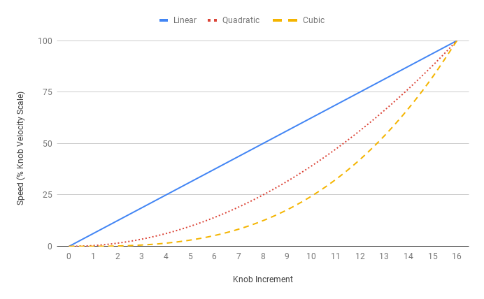
Interpolation
- 1
- Linear
- 2
- Quadratic
- 3
- Cubic
- Reply Data
Interpolation
- Persistence
- Non-volatile
Specifies the relationship between knob increments and velocity when Knob Movement Mode is set to Velocity Mode. For instance, if set to 2 (Quadratic), the velocity will change quadratically with each increment of the knob.
The different profiles are shown below. No matter which profile is selected, Knob Velocity Scale will be reached in 16 increments.
Error Codes
This command may return the following error codes:
- 112
-
Knob Velocity Profile Invalid
The requested knob velocity profile is invalid.
See also Error (Cmd 255)
Set Acceleration Only (Cmd 113)
Sets the acceleration used when increasing speed
- Data
-
Acceleration
0 to 2,147,483,647
- Reply Data
Acceleration
- Persistence
- Non-volatile
Specifies the acceleration used for most motion trajectories. The deceleration is set separately using Deceleration Only. The Acceleration setting and Acceleration Only setting have the same value. If the Acceleration setting is changed, the Acceleration Only setting is also updated.
Error Codes
This command may return the following error codes:
- 113
-
Acceleration Only Invalid
The requested acceleration is out of range.
See also Error (Cmd 255)
Set Deceleration Only (Cmd 114)
Sets the deceleration used when decreasing speed
- Data
-
Deceleration
0 to 2,147,483,647
- Reply Data
Deceleration
- Persistence
- Non-volatile
Specifies the deceleration used for most motion trajectories. The acceleration is set separately using Acceleration Only. If the Acceleration setting is changed, the Deceleration Only setting is updated to the same value.
Error Codes
This command may return the following error codes:
- 114
-
Deceleration Only Invalid
The requested deceleration is out of range.
See also Error (Cmd 255)
Set Move Tracking Mode (Cmd 115)
Enables Move Tracking (Cmd 8) messages
- Data
-
Move tracking mode
- 0
Disabled
- 1
Enabled
- Reply Data
-
Move tracking mode
- Persistence
- Non-volatile
When Move Tracking Mode is set to 1 Move Tracking (Cmd 8) messages will be sent at the Move Tracking Period during most move commands. Similarly, for products with knobs, Manual Move Tracking (Cmd 10) messages will be sent during knob-initiated, constant-velocity moves, provided Manual Move Tracking Disabled Mode allows them as well.
Error Codes
This command may return the following error codes:
- 115
-
Move Tracking Mode Invalid
The requested move tracking mode is invalid.
See also Error (Cmd 255)
Example: Enabling move tracking messages
When Move Tracking Mode is set to 0, the device will not produce Move Tracking (Cmd 8) messages:
  [0, 20, 100000] →  // Request to all devices, Move Absolute, Position 100000
← [1, 20, 100000]    // Response from device 1, Move Absolute, Position 100000
                     // (device at target position)
Conversely, when Move Tracking Mode is set to 1, the device will produce Move Tracking (Cmd 8) messages like the following:
  [0,  20, 100000] →  // Request to all devices, Move Absolute, Position 100000
← [1, 115,  19892]    // Response from device 1, Move Tracking, Position 19892
← [1, 115,  43320]    // Response from device 1, Move Tracking, Position 43320
← [1, 115,  66767]    // Response from device 1, Move Tracking, Position 66767
← [1, 115,  90195]    // Response from device 1, Move Tracking, Position 90195
← [1,  20, 100000]    // Response from device 1, Move Absolute, Position 100000
                      // (device at target position)
Set Manual Move Tracking Disabled Mode (Cmd 116)
Disables messages resulting from knob-related actions
- Data
-
Manual move tracking disabled mode
- 0
Manual move tracking enabled
- 1
Manual move tracking disabled
- Reply Data
-
Manual move tracking disabled mode
- Persistence
- Non-volatile
When this setting is set to 1, the device will not produce messages due to knob-related actions. When it is set to 0, the device will produce the following messages:
- Home (Cmd 1) if the device reaches a limit sensor during a knob-initiated move and, as a result, performs the homing algorithm
- Manual Move Tracking (Cmd 10) at a rate set by Move Tracking Period while performing knob-initiated, constant-velocity moves
- Manual Move (Cmd 11) when knob-initiated, displacement moves finish
- Stop (Cmd 23) when the axis stops because of a knob press
- Set Knob Movement Mode (Cmd 109) when the knob mode is switched by pressing and holding the knob
Error Codes
This command may return the following error codes:
- 116
-
Manual Move Tracking Disabled Mode Invalid
The requested manual move tracking disabled mode is invalid.
See also Error (Cmd 255)
Example: Enabling manual move tracking messages
When Manual Move Tracking Disabled Mode is set to 0, the device will send messages like the following when using the knob in velocity mode:
// Knob in Velocity Mode
// Knob turned
← [1, 116, 19892]    // Response from device 1, Manual Move Tracking, Position 19892
← [1, 116, 43320]    // Response from device 1, Manual Move Tracking, Position 43320
// Knob pressed
← [1,  23, 63455]    // Response from device 1, Stop, Position 63455 (device stopped)
However, when Manual Move Tracking Disabled Mode is set to 1, using the knob in velocity mode will not produce messages:
// Knob in Velocity Mode
// Knob turned
// Knob pressed
// Deceleration time passed, device stopped
Set Move Tracking Period (Cmd 117)
Sets the time interval between Move Tracking (Cmd 8) or Manual Move Tracking (Cmd 10) messages
- Data
-
Move tracking period (ms)
10 to 65,535
- Reply Data
Move tracking period (ms)
- Persistence
- Non-volatile
The time between consecutive Move Tracking (Cmd 8) messages and, for products with a knob, Manual Move Tracking (Cmd 10) messages.
Error Codes
This command may return the following error codes:
- 117
-
Move Tracking Period Invalid
The requested move tracking period is invalid.
See also Error (Cmd 255)
Set Closed-Loop Mode (Cmd 118)
Sets the closed-loop operating mode
- Data
-
Closed-loop mode
- 0
-
Disabled
- 3
-
Position correction
- 5
-
Displacement recovery
- Reply Data
Closed-loop mode
- Persistence
Non-volatile
In closed-loop mode, the encoder-measured position is compared to the target position, and the difference is used to adjust the motion trajectory by:
- running a position control loop to improve accuracy,
- handling stalls, and
- detecting unexpected displacements when the axis is not moving.
When Closed-Loop Mode is set to 0 (disabled), the position read from the encoder will not be used to control the position of the axis. Slips, stalls, and displacements will only be detected when this setting is 3 (position correction) or 5 (displacement recovery).
A stepper motor can occasionally slip (when the rotating electric field cannot produce enough torque to drive the load, so four steps of the stepper motor are skipped). On stepper motor products with a motor encoder, when an axis slips with closed-loop mode enabled:
- Current Position is shifted by four full steps to better reflect the encoder position,
- a Slip Tracking (Cmd 12) reply is sent, and
- the blue LED turns on for 250 ms.
A stall occurs after a moving axis fails to keep up with the motion trajectory despite the motor applying maximum drive effort for a duration of Stall Timeout. A displacement occurs after a stationary axis is forced out of position for a duration of Stall Timeout. The behaviour after each of these events occurs is summarized in Table 1.
| Position Correction (3) | Displacement Recovery (5) | |
|---|---|---|
| Stall |
|
|
| Displacement |
|
|
Error Codes
This command may return the following error codes:
- 118
-
Closed-Loop Mode Invalid
The requested closed-loop mode is invalid
See also Error (Cmd 255)
Set Slip Tracking Period (Cmd 119)
Sets the time interval between Slip Tracking (Cmd 12) or Unexpected Position (Cmd 13) messages
- Data
-
Slip tracking period (ms)
0 or 10 to 65,535
A value of 0 disables slip tracking messages.
- Reply Data
Slip tracking period (ms)
- Persistence
- Non-volatile
The time between consecutive Slip Tracking (Cmd 12) or Unexpected Position (Cmd 13) messages that are sent while an axis is displacing or has slipped. See Closed-Loop Mode for a description of the Slip Tracking (Cmd 12) and Unexpected Position (Cmd 13) reply behaviour while an axis is displacing.
Set Stall Timeout (Cmd 120)
Sets the timeout used to report stalls and displacements
- Data
-
Stall timeout
0 to 65,535
- Reply Data
Stall timeout
- Persistence
- Non-volatile
Specifies the timeout, in milliseconds, for reporting stalls and displacements. Stalls and displacements are described in the Closed-Loop Mode documentation.
Error Codes
This command may return the following error codes:
- 120
-
Stall Timeout Invalid
The requested stall timeout is invalid.
See also Error (Cmd 255)
Set Baud Rate (Cmd 122)
Sets the baud rate used on the RS-232 previous and next ports
- Data
-
Baud rate
9600, 19200, 38400, 57600, 115200
- Reply Data
Baud rate
- Persistence
- Non-volatile
The device expects to receive, and will send, messages at this speed over its previous port. The next port also operates at this speed; therefore, if multiple devices are daisy-chained, they must all be configured to the same baud rate. When changing this setting, the reply will be sent at the old baud rate. The device will stop accepting commands at the old baud rate, but continue to forward replies from other devices. After the device receives no communication for 200 ms, it will resume communication at the new baud rate.
To change the Protocol setting and the Baud Rate setting at the same time, use Convert to ASCII (Cmd 124).
Error Codes
This command may return the following error codes:
- 122
-
Baud Rate Invalid
The requested baud rate is invalid.
See also Error (Cmd 255)
Example: Changing the baud rate of two devices
Change the baud rate of two daisy-chained devices by sending the command to both devices at once:
  [0, 122, 9600] →  // Request to all devices, Set Baud Rate, Baud Rate 9600
← [1, 122, 9600]    // Response from device 1, Set Baud Rate, Baud Rate 9600
← [2, 122, 9600]    // Response from device 2, Set Baud Rate, Baud Rate 9600
After 200 ms, both devices accept commands at 9600 baud.
Set Protocol (Cmd 123)
Sets the protocol used by the device
- Data
-
Protocol
- 1
-
Binary
- 2
- Reply Data
Protocol
- Persistence
- Non-volatile
This setting changes the protocol used by the device. The device replies and then waits until no other chained devices have communicated for 200 ms before changing the protocol. Any commands sent to the device during this 200 ms period are discarded with no reply sent.
To change the Protocol setting and the Baud Rate setting at the same time, use Convert to ASCII (Cmd 124).
Error Codes
This command may return the following error codes:
- 123
-
Protocol Invalid
The requested protocol is invalid.
See also Error (Cmd 255)
Example: Changing the protocol on two devices
Change the protocol of two daisy-chained devices to ASCII:
  [0, 123, 2] →  // Request to all devices, Set Protocol, Protocol 2
← [1, 123, 2]    // Response from device 1, Set Protocol, Protocol 2
← [2, 123, 2]    // Response from device 2, Set Protocol, Protocol 2
After 200 ms, both devices accept commands in the ASCII protocol.
Return Command Reference
The following section details Binary return commands. Use these commands to read the value of a specific setting.
Return Device ID (Cmd 50)
Returns the ID number of the device
- Reply Data
- Device ID
Specifies the model of Zaber device. Each model and its associated ID number is listed at Zaber Support - Device IDs.
Return Firmware Version (Cmd 51)
Returns the firmware version of the device
- Reply Data
- Version
A decimal is assumed before the last two digits. For example, a data value of 701 indicates firmware version 7.01.
The Binary protocol does not support upgrading firmware. To upgrade the device to the latest version of firmware see the ASCII Protocol Manual.
Return Power Supply Voltage (Cmd 52)
Returns the power supply voltage
- Reply Data
- Voltage
The voltage the power supply is providing, in decivolts. It is normal for the voltage to differ slightly from the power supply’s rated voltage.
Example: Reading the power supply voltage
  [0, 52,   0] →  // Request to all devices, Return Power Supply Voltage
← [1, 52, 477]    // Response from device 1, Return Power Supply Voltage, Voltage 477
The returned data value is in decivolts, so the actual voltage is 477 dV / 10 = 47.7 V.
Return Status (Cmd 54)
Returns the status of the device
- Reply Data
- Status
Possible status codes are as follows:
- 0
- The device is idle and is not performing any motion.
- 65
- The device is parked.
- 90
- The driver is disabled. The device cannot move.
- 93
- The peripheral is inactive. For more information about activating peripherals, see Appendix C: Configuring and Activating Peripherals.
- 99
- The device is performing a motion.
Return Firmware Build (Cmd 56)
The build number of the device’s firmware
- Reply Data
- Build number
The firmware build number uniquely identifies the firmware installed on the device. This is useful in the rare cases where multiple firmware builds share the same Firmware Version. It is not normally necessary to consult the build number.
Return Current Position (Cmd 60)
Returns the current absolute position of the axis
- Reply Data
- Position
Returns an absolute measure (with reference to the limits) of the position at which the controller expects the axis to currently be.
See the Physical Units section for information about unit conversions.
Return Serial Number (Cmd 63)
Returns the serial number of the device
- Reply Data
- Serial number
Every Zaber product has a unique serial number.
Return Digital Input Count (Cmd 67)
Returns the number of digital input channels
- Reply Data
- Digital input channel count
This command returns the number of digital input channels available on the device.
Introduced in 7.09
Return Digital Output Count (Cmd 70)
Returns the number of digital output channels.
- Reply Data
- Digital output channel count
This command returns the number of digital output channels available on the device.
Introduced in 7.09
Return Analog Input Count (Cmd 75)
Returns the number of analog input channels
- Reply Data
- Analog input channel count
This command returns the number of analog input channels available on the device.
Introduced in 7.11
Return Encoder Count (Cmd 82)
Returns the position of the device in encoder counts
- Reply Data
- Encoder count
Specifies the position of the device, measured with the encoder, in units of encoder counts.
The value of Encoder Count is 0 at power-up or after a system reset. From then on, the encoder count tracks the position of the device as it moves. The physical unit of an encoder count depends on the encoder scale and the particular encoder that is used, but it represents the smallest distance that will register as a change in position. The value of Encoder Count is unchanged by actions that change the position reference, such as setting Current Position or homing.
For devices with encoder calibration, Encoder Count is the raw, uncalibrated position measured with the encoder. The calibrated count can be read from Calibrated Encoder Count.
See Encoder Position for the same information in distance units.
Return Calibrated Encoder Count (Cmd 83)
Returns the calibrated position of the device in encoder counts
- Reply Data
- Calibrated encoder count
Specifies the calibrated position of the device, measured with the encoder, in units of encoder counts. See Encoder Count for the definition of an encoder count.
If calibration data is not being applied, this value is equal to Encoder Count. Refer to Calibration Type for more information on calibration.
See Encoder Position for the same information in distance units.
Return Calibration Type (Cmd 84)
Returns the type of calibration available for the device
- Reply Data
- Calibration type
Possible calibration types are:
- 0
-
None
No valid calibration is available
- 1
-
Linear encoder
Linear-encoder calibration data is available
- 2
-
Linear Open Loop
Linear open loop calibration data is available
Introduced in 7.28
- 3
-
General Encoder
General encoder calibration data is available (either linear or rotary)
Introduced in 7.47
This setting returns the type of calibration data which is available to the device. Some products are shipped with pre-loaded calibration data. On these products, this setting will be non-zero. The calibration data is applied automatically once the device has been homed.
If the calibration type specified by the peripheral’s calibration data is invalid for the current Peripheral ID, this setting returns 0 and Calibration Error will return 2.
Most users will not need to configure calibration data. To transfer calibration data between controllers, use Zaber Console (under the "Options" tab). Please contact Zaber Support if you need to load, print, or delete calibration data.
Example: Query calibration type of all devices
  [0, 84, 0] →  // Request to all devices, Return Calibration Type
← [1, 84, 0]    // Response from device 1, Return Calibration Type, None
← [2, 84, 1]    // Response from device 2, Return Calibration Type, Linear encoder
Return Calibration Error (Cmd 85)
Returns any calibration errors for the device
- Reply Data
- Calibration error
Possible return values are:
- 0
-
No errors
If calibration data has been loaded, it is being applied to the device. See Calibration Type to read the type of calibration being applied.
- 1
-
Device not homed
Valid calibration data has been loaded, but cannot be applied until the device is homed to the reference expected by its calibration data.
- 2
-
Calibration data inapplicable
The loaded calibration data is not supported by this axis. Double check that the Peripheral ID is correct.
- 3
-
Calibration data invalid
The loaded calibration data is not supported by this device. Try upgrading to the most recent firmware version. If the problem persists, please contact Zaber Support.
Enabling calibration requires homing the device (see Home (Cmd 1)). Manually setting Home Status without homing the device is insufficient. To keep calibration enabled over a power cycle without needing to home the device again, set Park State before unplugging it.
Example: Query calibration errors of all devices
  [0, 85, 0] →  // Request to all devices, Return Calibration Error
← [1, 85, 0]    // Response from device 1, Return Calibration Error, No Errors
← [2, 85, 1]    // Response from device 2, Return Calibration Error, Device not homed
Return Peripheral Serial Number (Cmd 86)
Returns the serial number of the specified peripheral
- Reply Data
Peripheral serial number
Each Zaber peripheral is assigned a unique serial number.
When an autodetect peripheral is activated, Peripheral Serial Number will be updated to match Pending Peripheral Serial Number. This value is reset to 0 when Peripheral ID is changed while the peripheral is unplugged.
On peripherals without the autodetect feature, the controller does not know the serial number of the peripheral, so Peripheral Serial Number is always set to 0.
Introduced in 7.11
Return Encoder Position (Cmd 89)
Returns the position of the device measured with the encoder
- Reply Data
- Encoder position in distance units
Specifies the position of the device, measured with the encoder, in distance units.
Encoder Position returns Encoder Count translated into the same reference frame as Current Position and into distance units (see Physical Units).
On calibrated devices, Calibrated Encoder Count is used in place of Encoder Count to compute Encoder Position. Refer to Calibration Type for more information on calibration.
Return Pending Peripheral ID (Cmd 91)
Returns the peripheral ID of the autodetect-capable peripheral that is currently plugged in to the axis port
- Reply Data
Peripheral ID
If a peripheral with the autodetect feature is plugged into this axis of the controller, this setting returns the peripheral ID stored in its on-board memory. When no peripheral is plugged in, or when a peripheral without the autodetect feature is plugged in, this setting returns 0. All Zaber peripheral ID numbers are specified at Zaber Support - Peripheral IDs. The peripheral ID can also be found on the product label.
See Appendix C: Configuring and Activating Peripherals for more detailed information on configuring and activating peripherals.
Introduced in 7.11
Return Pending Peripheral Serial Number (Cmd 92)
Returns the serial number of the peripheral plugged into the controller
- Reply Data
Peripheral serial number
Each Zaber peripheral is assigned a unique serial number. If a peripheral with the autodetect feature is plugged into this axis of the controller, this setting returns the serial number stored in its on-board memory. When no peripheral is plugged in, or when a peripheral without the autodetect feature is plugged in, this setting returns 0. The peripheral serial number can also be found on the product label.
Introduced in 7.11
Reply-Only Command Reference
The following section details Binary reply-only commands. These commands are only ever sent from the device to the user, and indicate device status. All reply-only commands (except Error (Cmd 255) in some instances) are sent spontaneously by the device, and not in response to a user command.
Move Tracking (Cmd 8)
Indicates that a device is executing a move instruction
- Reply Data
- Current position
This response from a device indicates that the device is executing a move instruction. Responses of this type will be sent at the Move Tracking Period when Move Tracking Mode is enabled.
Limit Active (Cmd 9)
Indicates that a Move at Constant Speed (Cmd 22) has completed
- Reply Data
- Current position
This response from a device indicates that a Move at Constant Speed (Cmd 22) has finished normally. Generally this is because the device reached the end of travel (either Minimum Position or Maximum Position depending on the direction); however, Limit Active (Cmd 9) is also sent after the device stops due to a Move at Constant Speed (Cmd 22) with a speed of zero.
Manual Move Tracking (Cmd 10)
Indicates that a device is executing a constant velocity move initiated by a knob rotation
- Reply Data
- Current position
This response from a device indicates that the device is executing a knob-initiated, constant-velocity move. Responses of this type will be sent at the Move Tracking Period as long as they have not been disabled via Manual Move Tracking Disabled Mode.
Manual Move (Cmd 11)
Indicates that a device has completed a displacement move initiated by a knob rotation
- Reply Data
- Current position
This response from a device indicates that the device has completed a knob-initiated, displacement move. Responses of this type will be sent as long as they have not been disabled via Manual Move Tracking Disabled Mode.
Slip Tracking (Cmd 12)
Indicates a slip or displacement.
- Reply Data
- Encoder position
If Closed-Loop Mode is set to 5 (displacement recovery), slip tracking messages are sent as soon as a stationary device is forced out of position.
If Closed-Loop Mode is enabled (i.e., is non-zero), when the device slips a slip tracking message will be sent.
Use Slip Tracking Period to configure the time between slip tracking messages or to disable the replies. See Closed-Loop Mode for more detailed information about closed-loop behaviour.
Unexpected Position (Cmd 13)
Indicates a stall or displacement.
- Reply Data
- Encoder position
If Closed-Loop Mode is set to 3 (position correction), unexpected position messages are sent as soon as a stationary device is forced out of position. In this mode, an unexpected position message is also sent when a stall occurs on a moving axis.
If Closed-Loop Mode is set to 5 (displacement recovery), an unexpected position message is sent once a displaced device successfully returns to the pre-displaced position.
See Closed-Loop Mode for a description of the conditions that cause the Unexpected Position (Cmd 13) reply to be sent.
Use Slip Tracking Period to configure the time between unexpected position messages or to disable the replies. See Closed-Loop Mode for more detailed information about closed-loop behaviour.
Error (Cmd 255)
Indicates that an error has occurred
- Reply Data
- Error code
This reply indicates that an error has occurred. The error code in the message data indicates the type of error and is typically the number of the command that caused the error, but not always. The device may send an error as a reply to an invalid command, or it may send an error spontaneously (i.e., not in response to a user command).
1-
Cannot Home
The device has travelled a long distance without triggering the home sensor. It may be stalling or slipping.
Sent by:
2-
Device Number Invalid
The requested device number is out of range.
Sent by:
14-
Voltage Low
The power supply voltage is too low. This error is sent spontaneously.
15-
Voltage High
The power supply voltage is too high. This error is sent spontaneously.
18-
Stored Position Invalid
The position stored in the requested register is no longer valid. This is probably because the maximum range was reduced.
Sent by:
20-
Absolute Position Invalid
The requested target position is out of range.
Sent by:
21-
Relative Position Invalid
The requested target position is out of range.
Sent by:
22-
Velocity Invalid
The requested velocity is out of range.
Sent by:
36-
Restore Settings Data Invalid
The requested peripheral ID is invalid or not supported by the controller. Data must be 0 on products with integrated controllers.
Sent by:
37-
Resolution Invalid
The requested microstep resolution is invalid.
Sent by:
38-
Run Current Invalid
The requested run current is out of range.
Sent by:
39-
Hold Current Invalid
The requested hold current is out of range.
Sent by:
41-
Home Speed Invalid
The requested home speed is out of range.
Sent by:
42-
Speed Invalid
The requested target speed is out of range.
Sent by:
43-
Acceleration Invalid
The requested target acceleration is out of range.
Sent by:
44-
Maximum Position Invalid
The requested maximum position is out of range.
Sent by:
45-
Current Position Invalid
The requested position is out of range.
Sent by:
47-
Offset Invalid
The requested home offset is out of range or would produce invalid device bounds.
Sent by:
48-
Alias Invalid
The requested alias is out of range.
Sent by:
53-
Setting Invalid
The requested setting command number is invalid in this firmware version or on this device.
Sent by:
64-
Command Invalid
The requested command number is invalid in this firmware version or on this device.
65-
Park State Invalid
The requested park state is invalid or the device cannot park because it is in motion.
Sent by:
67-
Temperature High
The device detected a high internal temperature. It may be overheating. This error is sent spontaneously.
68-
Digital Input Pin Invalid
The requested digital input pin does not exist.
Sent by:
71-
Digital Output Pin Invalid
The requested digital output pin does not exist.
Sent by:
74-
Digital Output Mask Invalid
The requested mask sets one or more nonexistent digital output pins to 1.
Sent by:
76-
Analog Input Pin Invalid
The requested analog input pin does not exist.
Sent by:
78-
Move Index Number Invalid
The requested target index is invalid.
Sent by:
79-
Index Distance Invalid
The requested index distance is invalid.
Sent by:
80-
Cycle Distance Invalid
The requested cycle distance is invalid.
Sent by:
81-
Filter Holder ID Invalid
The requested filter holder ID is invalid.
87-
Absolute Force Invalid
The requested force is out of range.
101-
Auto Reply Disabled Mode Invalid
The requested auto reply disabled mode is invalid.
Sent by:
102-
Message ID Mode Invalid
The requested message ID mode is invalid.
Sent by:
103-
Home Status Invalid
The requested home status is invalid.
Sent by:
105-
Auto-Home Disabled Mode Invalid
The requested auto-home disabled mode is invalid.
Sent by:
106-
Minimum Position Invalid
The requested minimum position is out of range.
Sent by:
107-
Knob Disabled Mode Invalid
The requested knob disabled mode is invalid.
Sent by:
108-
Knob Direction Invalid
The requested knob direction is invalid.
Sent by:
109-
Knob Movement Mode Invalid
The requested knob movement mode is invalid.
Sent by:
110-
Knob Jog Size Invalid
The requested knob jog size is invalid.
Sent by:
111-
Knob Velocity Scale Invalid
The requested maximum knob speed is out of range.
Sent by:
112-
Knob Velocity Profile Invalid
The requested knob velocity profile is invalid.
Sent by:
113-
Acceleration Only Invalid
The requested acceleration is out of range.
Sent by:
114-
Deceleration Only Invalid
The requested deceleration is out of range.
Sent by:
115-
Move Tracking Mode Invalid
The requested move tracking mode is invalid.
Sent by:
116-
Manual Move Tracking Disabled Mode Invalid
The requested manual move tracking disabled mode is invalid.
Sent by:
117-
Move Tracking Period Invalid
The requested move tracking period is invalid.
Sent by:
118-
Closed-Loop Mode Invalid
The requested closed-loop mode is invalid
Sent by:
119-
Slip Tracking Period Invalid
The requested slip tracking period is invalid.
Sent by:
120-
Stall Timeout Invalid
The requested stall timeout is invalid.
Sent by:
122-
Baud Rate Invalid
The requested baud rate is invalid.
Sent by:
123-
Protocol Invalid
The requested protocol is invalid.
Sent by:
124-
Baud Rate or Protocol Invalid
The requested baud rate is not supported in the ASCII protocol.
Sent by:
255-
Busy
Another command is executing and cannot be pre-empted. Either stop the previous command or wait until it finishes before trying again.
257-
System Error
The device has experienced a critical system error. This should not occur during normal operation. Please contact Zaber Support if this occurs.
401-
Storage full
The device has experienced a critical storage error. This should not occur during normal operation. Please contact Zaber Support if this occurs. This error may be sent by any command that saves data persistently (e.g., any set command).
1600-
Save Position Invalid
The requested stored position index is out of range.
Sent by:
1601-
Save Position Not Homed
Store Current Position is not allowed until the device has been homed.
Sent by:
1700-
Return Position Invalid
The requested stored position index is out of range.
Sent by:
1800-
Move Position Invalid
The requested stored position is out of range.
Sent by:
1801-
Move Position Not Homed
Move to Stored Position is not allowed until the device has been homed.
Sent by:
6501-
Device Parked
The device is currently parked. Use Park State or Home (Cmd 1) to unpark the device before requesting a move.
Sent by:
9001-
Driver Disabled
The device has disabled the driver due to an overheating or over-current condition, or because the driver voltage is outside the normal operating range. The device cannot move. To re-enable the driver, send the Reset (Cmd 0) command.
Sent by:
9301-
Peripheral Inactive
The axis is inactive. See Appendix C: Configuring and Activating Peripherals for more information about activating peripherals.
Sent by:
Appendix A: Available Serial Ports
Windows
To find available serial devices on Windows:
- Start the Device Manager by opening Search or Run from the Start Menu, typing
Device Manager, and pressing Enter - Expand the Ports (COM & LPT) category
- In this example there are two serial ports available (COM3 and COM8), which are both USB adaptors.
- To determine which one corresponds to the USB serial cable connected to the Zaber device, unplug and plug in the cable, to see which one appears and disappears.
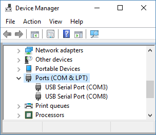
Linux
To find available serial devices on Linux:
- Find all serial ports
- Open a terminal and execute the following command:
dmesg | grep -E ttyU\?S↵ - The available ports should be listed similar to the following:
[ 2.029214] serial8250: ttyS0 at IO 0x3f8 (irq = 4) is a 16550A
[ 2.432572] 00:07: ttyS0 at IO 0x3f8 (irq = 4) is a 16550A
[ 2.468149] 0000:00:03.3: ttyS4 at IO 0xec98 (irq = 17) is a 16550A
[ 13.514432] usb 7-2: FTDI USB Serial Device converter now attached to ttyUSB0
In this example, there are 3 serial ports available:ttyS0,ttyS4, andttyUSB0(a USB adaptor). - To determine which one corresponds to the USB serial cable connected to the Zaber device, try repeating the command with and without the cable connected to the computer, to see which one appears and disappears.
- Open a terminal and execute the following command:
- Check the port permissions
- Using the ports found in the example above, execute the following command:
ls -l /dev/tty{S0, S4, USB0}↵ - The permissions for each port should be listed similar to the following:
crw-rw---- 1 root dialout 4, 64 Oct 31 06:44 /dev/ttyS0
crw-rw---- 1 root dialout 4, 68 Oct 31 06:45 /dev/ttyS4
crw-rw---- 1 root dialout 188, 0 Oct 31 07:58 /dev/ttyUSB0
This shows that a user must berootor a member of thedialoutgroup to access the ports.
- Using the ports found in the example above, execute the following command:
- Check and update group permissions
- List the groups the current user is in with the following command:
groups↵ - The output will be similar to the following:
adm cdrom sudo dip plugdev users lpadmin sambashare
Notice thatdialoutis not in the list - If necessary, add the current user to the
dialoutgroup with the following command:sudo adduser $USER dialout↵Note: Group membership will not take effect until the next logon
- List the groups the current user is in with the following command:
macOS
To find available serial devices on macOS:
- Open a terminal and execute the following command:
ls /dev/cu.*serial*↵- The available ports should be listed similar to the following:
/dev/cu.usbserial-FTB3QAET
/dev/cu.usbserial-FTEJJ1YW
In this example, there are 2 serial ports available, both of which happen to be USB adaptors. - There may be other devices that match this query, such as keyboards or some web cameras. To determine which one corresponds to the USB serial cable connected to the Zaber device, try repeating the command with and without the cable connected to the computer, to see which one appears and disappears.
- The available ports should be listed similar to the following:
Appendix B: Message Data Conversion Algorithm
The four data bytes in a Binary message (i.e., bytes three through six) often need to be converted to or from a single integer value. The bytes form a signed 32-bit data value, where byte three is the least significant byte and byte six the most significant byte. The following pseudo-code is one way of implementing the conversions.
See the Message Format section for a complete description of the Binary message format.
Example: Converting an integer into Binary message data bytes
If Cmd_Data < 0 then Cmd_Data = 256^4 + Cmd_Data    // Handles negative data values by
                                                    // calculating the two’s complement
Cmd_Byte_6 = Cmd_Data / 256^3
Cmd_Data = Cmd_Data - 256^3 * Cmd_Byte_6
Cmd_Byte_5 = Cmd_Data / 256^2
Cmd_Data = Cmd_Data - 256^2 * Cmd_Byte_5
Cmd_Byte_4 = Cmd_Data / 256
Cmd_Data = Cmd_Data - 256 * Cmd_Byte_4
Cmd_Byte_3 = Cmd_Data
Example: Converting Binary message data bytes into an integer
Reply_Data = 256^3 * Reply_Byte_6 + 256^2 * Reply_Byte_5 + 256 * Reply_Byte_4 + Reply_Byte_3
If Reply_Byte_6 > 127 then Reply_Data = Reply_Data - 256^4    // Handles negative data values by
                                                              // calculating the two’s complement
Appendix C: Configuring and Activating Peripherals
Each Zaber peripheral is identified by a unique peripheral ID. The controller uses this ID to properly configure the driver for the peripheral. The value in the Peripheral ID setting identifies the peripheral for which the controller is currently configured. The value in the Pending Peripheral ID setting identifies the autodetect peripheral which is currently plugged into the controller. All Zaber peripheral ID numbers are specified at Zaber Support - Peripheral IDs.
Each unique peripheral is given its own serial number. The value in the Peripheral Serial Number setting identifies the serial number of the peripheral for which the controller is currently configured. The value in the Pending Peripheral Serial Number setting identifies the serial number of the autodetect peripheral which is currently plugged into the controller.
Autodetect peripherals
- If the axis is in unused mode (i.e., Peripheral ID is 0), the controller will automatically set Peripheral ID to Pending Peripheral ID, load settings, and Activate the peripheral.
- If the axis is already properly configured for the peripheral that is plugged in (i.e., Peripheral ID already matches Pending Peripheral ID and Peripheral Serial Number is either 0 or matches Pending Peripheral Serial Number), the controller will automatically Activate the peripheral. If Peripheral Serial Number is 0, the controller will set it to Pending Peripheral Serial Number. Other settings will retain their previous values.
- If the controller is not properly configured for the plugged-in peripheral (i.e., either Peripheral ID does not match Pending Peripheral ID or Peripheral Serial Number does not match Pending Peripheral Serial Number), the controller will not automatically activate the peripheral. The yellow LED will fade in and out every two seconds. To load the new configuration, send the Activate command. This will reset axis-scope settings to their default values.
- If Pending Peripheral ID is an ID that is not supported by this controller or firmware version, the axis will remain inactive.
When Peripheral ID is non-zero and the controller detects that the configured peripheral is not plugged in, it will deactivate the driver and set the device status to 93.
Peripherals without the autodetect feature
For peripherals without the autodetect feature, (i.e., those whose product name does not end with the letter "A", or those purchased before June 2020), the firmware cannot identify the ID which is plugged in. Before using the peripheral, it is important to set Peripheral ID to the appropriate value. On these products, Pending Peripheral ID, Pending Peripheral Serial Number, and Peripheral Serial Number will always be 0.
Although it cannot detect which peripheral is plugged in, the controller can sometimes detect when the peripheral has been unplugged or plugged back in. When it detects that the peripheral is not plugged in, the controller will deactivate the driver and set the device status to 93. The behaviour when the peripheral is plugged in or unplugged varies depending on the particular controller model and on whether or not the peripheral has an encoder.
- The controller will always detect when the peripheral is unplugged.
- After plugging the peripheral back in, the controller will automatically reactivate the peripheral.
- The controller cannot detect when an unplug occurs - the driver will remain enabled.
- The controller cannot detect when a plug event occurs.
- To ensure that position information remains up-to-date, we recommend sending the Home (Cmd 1) command after plugging in a peripheral.
Unused mode
When an axis is not being used for any peripheral, it can be helpful to set Peripheral ID to 0, putting it into "unused" mode. When an axis is in unused mode, most commands will be rejected.
If an autodetect peripheral is plugged in while the axis is in unused mode, the controller will automatically set Peripheral ID to the new value and Activate it. Peripherals should be unplugged when not in use to prevent them from being automatically activated.
Example: Setting up a new autodetect peripheral
After receiving a new controller from Zaber, all axes should be in unused mode. If you want to be sure, verify that axis 1 is in unused mode by checking that Peripheral ID is 0:
  [1, 53, 66] →  // Request to device 1, Return Setting, Set Peripheral ID
← [1, 66,  0]    // Response from device 1, Set Peripheral ID, 0
Now, disconnect power from the controller and plug in the peripheral. Once that is done, power-up the controller. The controller should have automatically activated the peripheral. To verify this, read Peripheral ID again:
  [1, 53,    66] →  // Request to device 1, Return Setting, Set Peripheral ID
← [1, 66, 68332]    // Response from device 1, Set Peripheral ID, 68332
  [1, 54,     0] →  // Request to device 1, Return Setting, Return Status
← [1, 54,     0]    // Response from device 1, Return Status, Idle
The peripheral ID now matches the value on the peripheral’s label, and the Status is Idle. The peripheral is now ready for use.
Example: Switching from one autodetect peripheral to another
Suppose an LRM150A-T3A (with peripheral ID 66335) is currently configured on axis 1: You want to replace it with a VSR20A-T3A (peripheral ID 68701). First, power off the controller. Unplug the LRM150A-T3A and plug in the VSR20A-T3A in its place. Once that is done, power-up the controller.
  [1, 53,    66] →  // Request to device 1, Return Setting, Set Peripheral ID
← [1, 66, 66335]    // Response from device 1, Set Peripheral ID, 66335
  [1, 53,    66] →  // Request to device 1, Return Setting, Return Pending Peripheral ID
← [1, 93, 68701]    // Response from device 1, Return Pending Peripheral ID, 68701
At this time, Peripheral ID is still set to the previous value, indicating that the axis is still configured for the LRM150A-T3A. The Pending Peripheral ID setting is 68701, indicating that the VSR20A-T3A is plugged in. To start using the new peripheral, send the Activate command:
  [1, 93, 0] →  // Request to device 1, Activate, 0
← [1, 93, 0]    // Response from device 1, Activate, 0
  [1, 54, 0] →  // Request to device 1, Return Setting, Return Status
← [1, 54, 0]    // Response from device 1, Return Status, Idle
The axis is now active and ready for use.
Example: Setting up a peripheral which does not have the autodetect feature
With the peripheral unplugged, set Peripheral ID to the ID printed on the peripheral:
  [1, 66, 48332] →  // Request to device 1, Set Peripheral ID, 48332
← [1, 66, 48332]    // Response from device 1, Set Peripheral ID, 48332
Remove power from the controller and plug in the peripheral. Once that is done, power-up the controller. The controller should have automatically activated the peripheral. Read the device status to verify that the peripheral is active:
  [1, 54, 0] →  // Request to device 1, Return Setting, Return Status
← [1, 54, 0]    // Response from device 1, Return Status, Idle
The axis is now active and ready for use.