Scope
This manual defines Zaber’s ASCII protocol for all products with firmware versions 7.60 and below. Not all commands or settings are supported by all products. See the product-specific protocol manual for which commands and settings a product supports.
This manual defines Zaber’s ASCII protocol and the device settings and commands for the GENERIC PRODUCT running firmware version 7.60. Other products or firmware versions may support other commands or settings; see a product’s specific protocol manual for the commands and settings it supports.
If your device uses Firmware 6, refer to the Firmware 6 ASCII Protocol Manual. See here for instructions on how to tell which version your device uses.
Conventions
Conventions used throughout this document:
Fixed widthtype indicates ASCII characters communicated to and from a device.- The
↵symbol indicates a newline. When sending a command to a device,↵can be any combination of the Carriage Return (CR,‘\r’, ASCII code 13) and/or Line Feed (LF,‘\n’, ASCII code 10) characters. In responses from a device,↵includes both the Carriage Return and Line Feed characters. - When describing command parameters:
- Square brackets around a parameter indicate it is optional, e.g., [axis].
- Three periods following a parameter indicate that the parameter can be included more than once in a single command, e.g., axis
.... - An italicized parameter with a
<prefix and>suffix must be replaced with data, typically a number, when sending the command, e.g., <value>. - A pipe separating multiple parameters indicates that one of the listed parameters should be provided, e.g., abs|rel.
- Parameters enclosed in parentheses are grouped together with respect to operators, e.g., <channel>|(port <action>) means only <channel> or port <action> are valid; <channel> <action> is invalid.
Physical Units
Many of the setting values and command parameters described in this document relate to physical units, such as distance, voltage, and time. When a setting value is expressed in a real-world metric unit or in a scaled version of a unit, the units are described explicitly (such as a voltage specified in units of volts, or a current specified in 20 mA increments). In other cases, the value is unitless and some scaling factor is required to convert to a practical unit. Unitless values may be referred to in this document as the ‘data’ value.
In general, the documentation of each command or setting describes how to convert the relevant data values to real-world units. An exception is for values involving physical distances or positions (including speed/velocity and acceleration/deceleration), which are described here. This section is referenced whenever they’re used in a command or setting.
Converting data values involving distance or position to real-world values requires a device-specific conversion factor, which is listed in the "Specifications" section of the device’s User Manual.
For stepper motors, this conversion factor is called "Microstep Size". The value in the User Manual assumes the resolution setting is at the default value. If you have modified the resolution value, the Microstep Size can be converted:
The default resolution is available at Zaber Support - Device Settings.
For direct-drive motor products, this conversion factor is called "Encoder Count Size".
Position
For stepper motor products, all position and distance data values are in units of stepper motor microsteps. The conversion from distance or position data values to real-world units is given by:
For direct-drive motor products, all position and distance data values are in units of encoder counts. The conversion from distance or position data values to real-world units is given by:
Velocity
For stepper motor products, the conversion from velocity or speed data values to real-world units is given by:
For direct-drive motor products, the conversion from velocity or speed data values to real-world units is given by:
Acceleration
For stepper motor products, the conversion from acceleration or deceleration data values to real-world units is given by:
For direct-drive motor products, the conversion from acceleration or deceleration data values to real-world units is given by:
Quick Start
Connecting
Zaber devices support connecting to user equipment over standard serial connections using a human-readable, text-based protocol - Zaber’s ASCII protocol. This allows these devices to interface with a variety of equipment and software, including:
- Zaber Launcher
- Zaber Motion Library
- Zaber Console
- Terminal Emulators
- User programs
- PLCs
- Automation and Instrumentation packages
Zaber devices can be up and running in a matter of minutes, no matter what environment is being used.
X-Series devices typically communicate over RS-232 at 9600 or 115200 baud, with 8 bits, 1 stop bit and no parity, however please refer to the RS-232 Communications section of the device-specific User Manual for the correct settings. Characters are not echoed by the device, so if a terminal emulator is being used, it is advisable to turn on local echo.
Talking to Zaber Devices
Zaber devices listen for commands sent to them over a serial port and then immediately respond with a reply. Commands always begin with a / and end with a newline. Some commands take parameters, which are separated by spaces. Two example commands are:
/1 warnings↵
/1 system reset↵
Replies begin with a @, end with a newline, and have several space-delimited parameters in between. For example, the most common reply is:
@01 0 OK IDLE -- 0This can be broken down into:
@                   A reply.
 01                 The address of the device sending the reply
    0               The reply scope: 0 for the device or all axes, 1 onwards for an individual axis
      OK            The command succeeded.
         IDLE       The device isn’t moving (or BUSY if it is moving).
              --    No faults or warnings are active.
                 0  The return value, typically 0
Devices can also send two other types of messages: alerts, which start with !; and info, which start with #.
Talking to an Individual Device
If there is more than one device in a chain, sending the command /move abs 10000 will move all devices in the chain at once and return multiple responses. While this is a handy feature for initial setup, general use requires a way to instruct only an individual device to move.
Devices can be addressed by including their device number before the command. For example, the following command instructs only device 1 to move:
/1 move abs 10000↵
@01 0 OK BUSY -- 0
The valid device addresses are from 1 to 99 inclusive and can include a leading 0 for devices 1 to 9. For example, both 01 and 1 refer to device 1.
Talking to an Individual Axis
On multi-axis devices, commands of the form /command or /# command affect all axes of the device. In order to send a command to a single axis, provide an axis number after the device number.
Example: Moving a single axis
The following command instructs axis 1 on device 2 to move to position 10,000:
/2 1 move abs 10000↵
@02 1 OK BUSY -- 0
Note that the response scope is 1, indicating that the information in the reply applies to axis 1.
Example: Turning on a single lamp
The following command instructs lamp axis 1 on device 2 to turn on:
/2 1 lamp on↵
@02 1 OK BUSY -- 0
Note that the response scope is 1, indicating that the information in the reply applies to axis 1.
Talking to Multiple Axes
On multi-axis devices, commands of the form /command or /# command affect all axes of the device.
The firmware processes an axis-scope command addressed to multiple axes in two steps.
First, it selects the axes which support the command. If no axes support the command, the command will be rejected with the reason BADCOMMAND.
Then, if at least one axis supports the command, firmware will validate the command on all the supported axes. The command will only execute if validation succeeds on all of these axes; if validation fails on any single axis, the command will be rejected with a reason other than BADCOMMAND.
Settings that are not supported on an axis will return NA when read with a get command.
- The axis is in unused mode
- The command or setting may pertain to a feature that requires hardware that the axis does not have. For example, settings to configure an encoder are not supported on axes with no encoder.
- A set command is trying to modify a read-only setting.
BADCOMMAND, the command is not supported on that axis. Example: Reading the position of multiple axes
Read the position of all axes on a 3-axis controller:
/1 get pos↵
@01 0 OK IDLE -- 12345 NA 0- The peripheral on axis 1 is at position 12,345.
- Axis 2 does not support the command, so the pos value returned is
NA. This likely indicates it is in unused mode. - The peripheral on axis 3 is at position 0.
Note that the response scope is 0, indicating that the information in the reply applies to all axes.
Example: Setting the maximum speed on multiple axes at once
Set maxspeed to 100,000 on all axes of a 3-axis controller:
/1 set maxspeed 100000↵
@01 0 OK IDLE -- 0
Now verify the result by reading maxspeed on all axes:
/1 get maxspeed↵
@01 0 OK IDLE -- 10000 NA 100000- Axes 1 and 3 now have maxspeed set to 100,000.
- Axis 2 returned
NA, indicating that the maxspeed setting is not supported on that axis.
Example: Reading a setting on multiple axes
Read the maximum position of all axes on a 2-axis device:
/1 get limit.max↵
@01 0 OK IDLE -- 640000 768000- The maximum position of axis 1 is 640,000.
- The maximum position of axis 2 is 768,000.
Note that the response scope is 0, indicating that the information in the reply applies to all axes.
Example: Reading the maximum current of all lamp axes
Read the maximum current of each lamp on an X-LCA:
/1 get lamp.current.max↵
@01 0 OK IDLE -- 1.000 NA 0.8000 NA- The lamp peripheral on axis 1 has a maximum current of 1 A.
- Axis 2 is unused, so the value returned is
NA. - The lamp peripheral on axis 3 has a maximum current of 0.8 A.
- Axis 4 is unused, so the value returned is
NA.
Note that the response scope is 0, indicating that the information in the reply applies to all axes.
Making it Move
It is recommended that the first movement command sent to a device after it is connected and powered is the home command. The device will move to the home limit sensor and establish a reference position:
/home↵
@01 0 OK BUSY WR 0
If the device hasn’t been homed, motion commands may not work as expected. The controller’s position limits will not match the physical limits, absolute movements will not move to expected positions, and relative movements the device is capable of may be rejected for being outside the travel range. Replies from the device will include the No Reference Position (WR) flag:
/move rel 10000↵
@01 0 RJ IDLE WR BADDATA
Once the device has been homed, make the device move by sending a move command. For example, to move a distance of 10,000 forward from the current position:
/move rel 10000↵
@01 0 OK BUSY -- 0
To move to the absolute position 10,000, measured from the home position, regardless of the current position:
/move abs 10000↵
@01 0 OK BUSY -- 0
See the Physical Units section for information about unit conversions.
Changing a Device Setting
All of the device settings are read and modified using the get and set commands. For example, to query the device maxspeed:
/get maxspeed↵
@01 0 OK IDLE -- 153600
The maximum speed setting is currently 153,600.
See the Physical Units section for information about unit conversions.
On a multi-axis device, sending an axis-scope command without specifying an axis returns a value for each of the axes. For example:
/get maxspeed↵
@01 0 OK IDLE -- 153600 153600
To set the maximum speed, for example, to be twice what was read:
/set maxspeed 307200↵
@01 0 OK IDLE -- 0
On a multi-axis device, the command above sets the maximum speed for all axes.
Message Format
The ASCII protocol uses a command-reply model, such that:
- The user must initiate all communication by sending a device a command.
- Unless explicitly disabled, a device always responds with one reply immediately after a command has been received (see the Message IDs section for how to disable replies). Select commands will return additional Info messages.
- Unless explicitly enabled, a device never sends a message unless in response to a command (see Alerts for more information).
The content of the message is space-delimited, with consecutive spaces being treated as a single space. There is only one command or response per message. Sending multiple commands in a single message is not supported.
Reserved Characters
The following characters are reserved and their use is restricted:
-
/,@,#, and!indicate the message type and must be the first byte of a message. - Carriage Return (CR,
‘\r’, ASCII code 13), Line Feed (LF,‘\n’, ASCII code 10), or any combination thereof, indicate a newline (collectively represented as↵) and the end of a message. All newline characters must be the last bytes of a message. -
:indicates the start of a message checksum and must be followed by a two-byte checksum and↵. See Checksums for more details. -
\indicates a line continuation for firmware versions 7.12 and above and must only appear immediately prior to↵or the:of a message checksum. It may appear in replies or info messages. In firmware versions 7.26 and above it may also appear in command messages. See Line Continuation for more details. -
\is reserved in firmware versions 7.11 and below and may not be present anywhere in a message. - Bytes 128 to 255 are reserved and may not be present anywhere in a message.
Any message that includes these characters in positions other than those specified above is malformed. If a device receives a malformed command it may not respond, respond with the reason BADCOMMAND, or interpret the command in unexpected ways. For example, including ! as an argument to a command will not elicit a reply:
/tools echo hi!↵Similarly, including newline characters, ↵, anywhere but the last bytes of a command will truncate the message, producing an unexpected reply:
/tools echo hello↵world↵
@01 0 OK IDLE -- hello
Commands
Users send commands to one or more devices, which always and immediately respond with a reply. See the Command Reference section for all the available commands. A command instructs the device to perform an operation. An example of a typical command message and associated fields is:
╭────────────────────── /
│╭───────────────────── [n]
││ ╭─────────────────── [a]
││ │ ╭───────────────── [i]
││ │ │  ╭────────────── x...
││ │ │  │       ╭────── [y...]
││ │ │  │       │    ╭─ [\][:CC]
││ │ │ ╭┴─╮ ╭───┴───╮├─ ff
/1 1 1 move abs 10000↵/-
Message Type
Size: 1 byte
The message type for a command is always
/.This field and the footer are the only required fields; all others are optional.
n-
Device Address
Size: 1+ bytes
The address indicates which device number should perform the command. The address is optional: if it is not included, or set to 0, all devices on the chain execute the command. Device addresses range from 1 to 99 inclusive.
Examples of acceptable addresses are:
0, 00, 1, 01, 000001, 76, 99, 0x00, 0x01, 0x5A, 0x5aInvalid addresses include:
100, -1, 0x65The addresses are out of range and while the message may be valid, no device will respond.
a-
Axis Number
Size: 1+ bytes
The axis number indicates which axis within a device should perform the command. The axis number is optional: if it is not included, or set to 0, the command is executed by all axes of the device. If it is included, the Device Address is then also required. Axis numbers range from 1 to 9 inclusive.
The axis number is further restricted by the number of axes that are actually present on the device. The device will reject commands with an axis number higher than what the device supports with the reason
BADAXIS.Examples of acceptable axis numbers are:
0, 00, 1, 01, 000001, 0x00, 0x01Invalid axis numbers include:
76, 99, 0xA, 0x0a, -1, 0x65These axis numbers are out of range, and the command will be rejected.
i-
Message ID
Size: 1+ bytes
The message ID is an optional field that can be included in any command, and causes responses (including reply and info responses) to the command to include the same message ID. If it is included, the Axis Number and Device Address are then also required.
For more information about message IDs, see Message IDs.
x...-
Command
Size: Variable
The command message data contains the command information. The contents are space-delimited.
The Command Reference covers the available commands.
y...-
Command Parameters
Size: Variable
This message data contains command parameters and data. The contents are space-delimited and case-sensitive. Any numerical values in the message data can either be in decimal format or in hexadecimal and prefixed with
0x.Negative values are prefixed with ‘
-’; positive values may optionally be prefixed with ‘+’.The Command Reference covers the contents of the parameters field for the available commands.
\-
Line Continuation
Size: 1 byte
Indicates that the command is not complete and the controller should expect subsequent packets containing the rest of the command. See Line Continuation for more details.
Introduced in 7.26
:CC-
Message Checksum
Size: 3 bytes.
The message checksum is an optional parameter that, when provided, causes a device to reject a message that has been corrupted during transmission.
For more information about checksums, see Checksums.
ff-
Message Footer
Size: 1 - 2 bytes
The footer indicates end-of-message. For convenience, the device accepts any ASCII combination of carriage return (CR,
\r) and/or line feed (LF,\n) as a message footer. In a terminal emulator, this is included when the command is sent by pressing enter or return.
Smallest Command
The smallest valid command is /↵, which generates a response from all devices in the chain:
/↵
@01 0 OK IDLE -- 0
@03 0 OK IDLE -- 0
@02 0 OK IDLE -- 0
This can be used as a quick way to check the statuses of all devices and that they are communicating as expected.
Largest Command
The maximum command packet size is comm.packet.size.max comm.packet.size.max 80 80 (comm.packet.size.max) characters, including the / and ↵. Devices do not respond to command packets longer than this. In firmware versions 7.26 and above, Line Continuation can be used to send a larger command by splitting it into multiple packets.
Replies
The device sends a reply as soon as it has received a command and determined if it should respond. An example of a typical response message and associated fields is:
╭────────────────────── @
│╭───────────────────── n
││  ╭────────────────── a
││  │ ╭──────────────── [i]
││  │ │  ╭───────────── fl
││  │ │  │   ╭───────── s
││  │ │  │   │   ╭───── w
││  │ │  │   │   │  ╭── x
││  │ │  │   │   │  │╭─ [\][:CC]
││  │ │  │  ╭┴─╮ │  │├─ ff
@01 0 01 OK IDLE -- 0↵@-
Message Type
Size: 1 byte
The message type for a reply is always
@. n-
Device Address
Size: 2 bytes
The address indicates the address of the device sending the message, and is always formatted as two digits.
a-
Axis Number
Size: 1 byte
The axis number limits the scope of the reply, and has a value in the range of 0 to 9. An axis number between 1 and 9 indicates the reply applies specifically to that axis. An axis number of 0 indicates that the reply applies to the whole device and all axes on it.
i-
Message ID
Size: 2 bytes
The message ID of the command that elicited the reply. Omitted if the command had no message ID.
For more information about message IDs, see Message IDs.
fl-
Reply Flag
Size: 2 bytes
The reply flag indicates if the message was accepted or rejected and has one the following values:
OKThe command was valid and accepted by the device.
RJ-
The command was rejected. The data field of the message will contain one of the following reasons:
AGAINThe device cannot process the command right now. Send the command again. This response is only in replies to stream or pvt commands.
AXISONLY-
On a multi-axis device, the command must be addressed to a particular axis, but the axis number was
0or omitted. BADAXISThe command’s axis number was greater than the number of axes available.
BADCOMMANDThe command or setting was incorrect or invalid.
BADDATAThe command’s data was incorrect or out of range.
BADMESSAGEIDThe command included a message ID, but the ID was not either
--or a number from 0 to 99.BADSPLITThe command was split into multiple packets in an incorrect way. Possible causes include the parts having different axis numbers or message IDs, an incorrect packet counter value, incorrect positioning of
\characters, or the use of the line continuation feature in a renumber command. See Line Continuation for more details.BRAKECLOSED-
One of the specified axes has a closed brake so cannot move. Open the brake using the brake.mode setting.
CYCLICONLYThe command cannot be executed because it requires limit.cycle.mode to be set to Cyclic and limit.cycle.dist to be non-zero.
DEVICEONLYAn axis number was provided to a device-scope command.
DRIVERDISABLED-
One of the drivers is disabled because the driver is or was in an over-temperature, over-voltage, or over-current condition. Alternatively, it is possible that the device’s emergency stop input was activated or that the user disabled the driver with the driver disable command. See Warning Flags to determine the underlying cause. This rejection reason persists until the driver is successfully re-enabled with the driver enable command.
FULL-
The device cannot allocate more memory for information related to the command. See the documentation for the command that prompted this response for details of this rejection.
INACTIVE-
The command failed to execute because the axis is inactive. See Peripheral Inactive (
FZ) for more information. INVALIDLIMITS-
The process output cannot be turned on because voltage limits are not set correctly. See process on for more information.
LOCKSTEPAn axis cannot be parked, unparked, or moved using normal motion commands because it is part of a lockstep group. Use lockstep commands instead or disable the lockstep group first.
LONGWORDA word in a message was longer than comm.word.size.max characters.
NOACCESSThe command or setting is not available at the current access level.
NOTSINThe axis is not currently moving in response to a move sin command, so it cannot be stopped with the move sin stop command.
NOTSUPPORTED-
The axis cannot be activated because the connected peripheral is not supported by this version of firmware.
See Peripheral Not Supported (
FN) for more information. OVERDRIVELIMIT-
The axis cannot execute motion requests because it exceeded its overdrive energy limit and has entered the recovery state.
The axis cannot execute motion requests because it has not yet cooled sufficiently since exceeding its overdrive energy limit.
See Overdrive Limit Exceeded (
FR) for more information.The axis cannot execute motion requests because it exceeded its overdrive energy limit and has entered the recovery state.
PARKED-
The device cannot move because it is currently parked.
Use the tools parking unpark command to unpark the device.
PROCESSON-
The setting value cannot be changed because the process output is currently turned on. Use process off to turn the output off before changing the setting.
REMOTE-
The command cannot be executed because the device is in EtherCAT Remote Mode. See comm.ethercat.remote for more details.
REMOTEANDENABLED-
The command cannot be executed because the device is in EtherCAT Remote Mode and the axis is in the Operation Enabled CiA402 state. See comm.ethercat.remote for more details.
STATUSBUSY-
The device cannot execute the command because it is currently busy. For example, the command might require that the axis have the
IDLEstatus when it is insteadBUSY, or some other resource required for the command is already in use. SYSTEMERROR-
The device failed to execute the command due to a system failure. Use the system errors command to review errors.
TWISTED-
The device failed to execute a stream or pvt command on a lockstep group because the axes in the group are twisted beyond the allowable threshold and cannot correct for the twist. Send a lockstep move command to automatically untwist the axes before retrying the stream or pvt command. See the lockstep commands section for more information about twisting.
s-
Status
Size: 4 bytes
On devices that control motion axes, the device status is
BUSYwhen the axis is moving andIDLEotherwise. All motion commands, including stop, put the axis into theBUSYstate while they are being executed. During streamed motion, stream wait commands are considered to be busy, not idle. If the reply message applies to the whole device, the status isBUSYif any axis is busy andIDLEif all axes are idle.On devices that control lamps, the device status is always
IDLE.On devices that control processes, the device status is always
IDLE. w-
Warning Flag
Size: 2 bytes
The warning flag is the highest priority warning currently active for the device or axis, or
--when there are no warnings. For the list of warning flags, see Warning Flags. x...-
Data
Size: 1+ bytes
The contents and format of the data vary depending on the command the reply relates to. The data is
0for commands that don’t return specific information. \-
Line Continuation
Size: 1 byte
Indicates that the message cannot fit within the comm.packet.size.max comm.packet.size.max 80 80 (comm.packet.size.max) character limit of an ASCII packet and is incomplete. The remainder of the message will be sent in subsequent Info packet(s). See Line Continuation for more details.
Introduced in 7.12
:CC-
Message Checksum
Size: 3 bytes
The comm.checksum setting determines whether a reply includes a checksum.
For more information about checksums, see Checksums.
ff-
Message Footer
Size: 2 bytes
The message footer is always composed of a CR-LF combination (
\r\n).
Replies on Multi-axis Devices
For replies with an axis number of 0, the status and warning flags apply to the whole device. If any axis on the device is moving, then the reply status is BUSY. Similarly the warning flags show the highest priority warning across all axes.
For replies with an axis number of 1 or above, the status and warning flags only apply to the axis indicated.
Warning Flags
Each reply message includes a warning flag, indicating whether any device fault or warning is active. If more than one condition is active, it shows the one with highest priority.
- Fault
-
Flags in this category indicate an event that has immediate consequences to the behaviour of the device. As a result, the device may have deviated from its trajectory or stopped.
- Warning
-
Flags in this category indicate that continued operation may lead to unexpected behaviour.
- Note
-
Flags in this category indicate that an event should be noted by the user before continued operation, but is part of normal device operation.
The warning flags are defined as follows, with the highest priority first:
FF-
Fault - Critical System Error
The device has experienced a critical system error. This should not occur during normal operation. Please contact Zaber Support with the response from system errors if this occurs.
FN-
Fault - Peripheral Not Supported
The connected peripheral is not supported by this version of firmware.
We recommend upgrading the controller to the latest firmware version (see Firmware Upgrades). To read the currently installed firmware version, consult the version setting. To look up which firmware versions support your peripheral, see Device Settings.
FZ-
Fault - Peripheral Inactive
The peripheral is inactive.
Until the peripheral is reactivated, all motion commands will be rejected.
Until the peripheral is reactivated, all lamp commands will be rejected.
On autodetect peripherals, this flag indicates one of the following:- One or more of the peripheral’s cables is not fully plugged in. Depending upon the order in which the cables are reconnected, activation may not happen automatically. In this case, send the activate command to manually activate the peripheral after reconnecting the cables.
- The peripheral that is plugged in is different from the peripheral for which the controller is currently configured. To rectify this, either plug in the correct peripheral, or send activate to accept the new configuration.
On peripherals without the autodetect feature, this flag indicates one of the following:- The peripheral.id setting is not correct. Check that it matches the value on the label of the peripheral.
- The peripheral is not plugged in.
- The peripheral is properly configured, but needs to be activated. Send the activate command.
This warning may be present at startup while the controller checks for the presence of autodetect peripherals.
See the peripheral settings section for more detailed information about peripheral configuration and activation.
FH-
Fault - Hardware Emergency Stop Driver Disabled
The device has disabled the driver in response to a hardware emergency stop signal.
This warning persists until the driver returns to normal operating conditions, the hardware emergency stop is deactivated, and the user re-enables the driver with a driver enable command.
FV-
Fault - Overvoltage or Undervoltage Driver Disabled
The device has disabled the driver in response to the driver voltage being outside the normal operating range. This can occur if:- a stall has occurred
- the motor is backdriven
- there is damage to the driver hardware
- there is a problem with the power supply
- the supply voltage is below the level needed to open the brake.
This warning persists until the driver voltage returns to normal operating conditions, and the user re-enables the driver with a driver enable command.
This warning may appear briefly at power-up.
FO-
Fault - Driver Disabled
The device has disabled the driver. There are several cases in which case this warning flag can appear:- This warning will appear after the user has sent a driver disable command. In this case, it will persist until the user re-enables the driver with a driver enable command.
- This warning may appear at power-up or after a reset, while the device starts up. On controllers, this warning may also appear after a peripheral is plugged in or activated, while the controller waits for the peripheral to power up. Once the device is ready, if driver.enable.mode is set to 1, the driver will be automatically enabled and the warning flag will be cleared.
- If driver.enable.mode is set to 0, this warning will appear after a peripheral is unplugged from a controller. It will persist until the user re-enables the driver with a driver enable command.
- It may also appear while executing certain commands or setting changes that require disabling the driver. If the driver was previously enabled, the driver will automatically be re-enabled once the device is ready.
- On brake products, this warning will occur if a non-recovered stall or displacement occurs. In this case, either the Stalled Stalled Stalled and Stopped (
FS) or Displaced When Stationary (WM) warning flag will also be raised. The Driver Disabled (FO) will persist until the user re-enables the driver with a driver enable command. - On EtherCAT products, this warning will appear whenever the device is in the Switch On Disabled, Ready To Switch On, Switched On, or Not Ready To Switch On CiA402 states. Several fault conditions can also disable the driver and cause this warning to appear when the device is in the Fault state. The driver will remain disabled until the user re-enables the driver with a driver enable command or via the CANopen Controlword (0x6040) object. See the CANopen Protocol Manual for more details.
Introduced in 7.11
FC-
Fault - Current Inrush Error
The device has disabled the driver due to an excessive inrush of current from the power supply. This may occur due to a problem with the driver or motor or load, motor, or load, or in rare cases during normal operation if the device attempts to draw more than system.current.max from its supply. It may also occur when power supplies are connected to or disconnected from a controller supporting multiple power supplies or devices in a daisy-chain.
This warning persists until the user re-enables the driver with a driver enable command.
In firmware versions 7.37 and below, this warning may appear at power-up or after a reset, while the device starts up. Once the device is ready, the driver is automatically enabled and the warning flag is cleared.
Introduced in 7.11
FM-
Fault - Motor Temperature Error
The device has disabled the driver due to an overheating motor.
This warning persists until the motor temperature returns to normal operating conditions and the user re-enables the driver with a driver enable command.
On a controller, this flag may appear when the peripheral is unplugged. It will be cleared when the peripheral is activated. See the peripheral settings section for more information on activating peripherals.
Warning: Continually driving the motor at power levels sufficient to repeatedly trigger this fault may permanently damage the motor.Introduced in 7.11
FD-
Fault - Driver Temperature/Current Error Driver Temperature/Current Error Driver Disabled
Called Driver Disabled in firmware versions 7.10 and below.
The device has disabled the driver due to an overheating driver or an over-current condition.
In firmware versions 7.10 and below, this also indicates that the device has disabled the driver in response to a driver disable command.
On products with encoders with firmware versions 7.08, 7.09, or 7.10, this warning may also appear when the device powers up, while the controller waits for the encoder to power up. Once the encoder is ready, the driver is automatically enabled and the warning flag is cleared.
This warning persists until the driver temperature and current return to normal operating conditions and the user re-enables the driver with a driver enable command.
FQ-
Fault - Encoder Error
The encoder-measured position may be unreliable. The encoder has encountered a read error due to poor sensor alignment, vibration, dirt or other environmental conditions. Reset the encoder reference position by sending system reset followed by a home operation.
On a controller, if the peripheral ID of a product is set but the peripheral is unplugged, this flag may appear. It will be cleared when the peripheral is activated. See the peripheral settings section for more information on activating peripherals.
On EtherCAT devices, the device will disable the driver and set the Driver Disabled (
FO) flag.This warning persists until acknowledged and cleared by the user with the warnings clear command.
Please contact Zaber Support if this error persists.
FI-
Fault - Index Error
The encoder has encountered a problem with the index mark and the home position may be unreliable. This could be due to poor sensor alignment, vibration, dirt, or other environmental conditions. A home operation is recommended to reset the encoder reference position.
This warning persists until acknowledged and cleared by the user with the warnings clear command.
Please contact Zaber Support if this error persists.
FA-
Fault - Analog Encoder Sync Error
The encoder-measured position may be unreliable due to a problem interpolating the encoder signals. This could be due to poor sensor alignment, dirt, or other environmental conditions. Reset the encoder reference position by sending system reset followed by a home operation.
On a controller, if the peripheral ID of a product is set but the peripheral is unplugged, this flag may appear. It will be cleared when the peripheral is activated. See the peripheral settings section for more information on activating peripherals.
This warning persists until acknowledged and cleared by the user with the warnings clear command.
Please contact Zaber Support if this error persists.
FR-
Fault - Overdrive Limit Exceeded
The axis exceeded its overdrive energy limit and has entered the recovery state. The axis has stopped or is in the process of stopping.
This warning persists until acknowledged and cleared by the user with the warnings clear command.
The axis exceeded its overdrive energy limit and either has stopped or is in the process of stopping. The driver has temporarily restricted its current output to driver.current.continuous, and will temporarily reject motion commands. The axis driver will begin accepting motion requests and allowing overdrive currents after driver.i2t.measured and motor.i2t.measured have both fallen below 100 %.
This warning persists until acknowledged and cleared by the user with the warnings clear command.
See the driver settings section for more details on continuous and overdrive current limits.
The axis exceeded its overdrive energy limit and has entered the recovery state. The axis has stopped or is in the process of stopping.
This warning persists until acknowledged and cleared by the user with the warnings clear command.
Introduced in 7.28
FS-
Fault - Stalled Stalled Stalled and Stopped
Called Stalled and Stopped in firmware versions 7.26 and below.
The axis detected a stall. The mechanism used for detecting stalls is described in Detecting Stalls and Displacements. A stall can also A stall can also Devices without encoders cannot detect stalls, but a stall can occur as a result of manually setting the pos, limit.cycle.mode, or limit.cycle.dist settings during certain types of motion, including:- While the axis is following a move sin trajectory
- While the axis is part of a lockstep group that is following a lockstep move sin trajectory
- While the axis is following a move track trajectory or the tracking portion of a move scan track once trajectory
- While the axis is part of a live stream sequence and is in motion or has queued motion segments
- While the axis is part of a live pvt sequence and is in motion
On EtherCAT devices, after the stall action has completed (cloop.stall.action), the device will disable the driver and set the Driver Disabled (
FO) flag.On brake products, after the stall action has completed (cloop.stall.action), the device will disable the driver and set the Driver Disabled (
FO) flag.This warning persists until acknowledged and cleared by the user with the warnings clear command.
FB-
Fault - Stream/PVT Sequence Bounds Error Stream Bounds Error Stream/PVT Sequence Bounds Error
The device could not execute a previously sent stream or pvt movement because it failed a precondition (e.g., motion exceeds device bounds, calls nested too deeply), or a PVT sequence ended with non-zero velocity, causing it to deviate from the prescribed path.
Obtain the error reason with the stream info or pvt info command.
This warning persists until acknowledged and cleared by the user with the warnings clear command or until the stream or PVT sequence is disabled with the stream setup disable or pvt setup disable command. Until the warning is cleared, no further streamed motions or PVT points can be sent to the failed stream or PVT sequence.
FP-
Fault - Interpolated Path Deviation
The device has terminated streamed or sinusoidal motion because it slipped and thus deviated from the requested path.
See cloop.enable for more information on slips.
This warning persists until acknowledged and cleared by the user with the warnings clear command.
This warning has been removed in firmware versions 7.09 and above.
FE-
Fault - Limit Error
A limit sensor is faulty, could not be found, or was found unexpectedly; or the axis would need to move outside of its limits to achieve the commanded motion
This warning persists until acknowledged and cleared by the user with the warnings clear command.
On a controller, this flag may appear when the peripheral is unplugged. It will be cleared when the peripheral is activated. See the peripheral settings section for more information on activating peripherals.
If the axis is part of a lockstep group, excessive twist may have prevented the axis from reaching the limit sensor.
While detecting the installed filter holder the device failed to find the away sensor or found it in an unexpected position.
While homing or spontaneously encountering a limit sensor, this flag may appear if the offset position dictated by limit.home.offset is outside the range limit.min to limit.max.
In firmware versions 7.37 and above, this flag may appear if the sensor position the tools gotolimit command tries to write to limit.min or limit.max is beyond the valid limits (-1,000,000,000 to 1,000,000,000).
This flag may appear during a move track command if the control loop needed to drive the axis beyond the valid limits or if the analog input signal became invalid.
This flag may appear during a move scan track once command if the command completed the scanning stage without locating a valid analog signal or if the resulting position after moving motion.tracking.scan.offset would be outside the valid travel range for the command.
FT-
Fault - Excessive Twist
Twist in the lockstep group exceeded the allowable tolerance setting or one of the axes has stalled (regardless of the twist tolerance), and movement has stopped.
This warning persists until acknowledged and cleared by the user with the warnings clear command.
WL-
Warning - Unexpected Limit Trigger
A movement operation did not complete due to a triggered limit sensor. This flag is set if a limit sensor interrupts a movement operation and the No Reference Position (
WR) warning flag is not present. This may be an indication that the axis has slipped or one of limit.min and limit.max is incorrect.This warning persists until acknowledged and cleared by the user with the warnings clear command.
On a controller, this flag may appear when the peripheral is unplugged. It will be cleared when the peripheral is activated. See the peripheral settings section for more information on activating peripherals.
WV-
Warning - Voltage Out of Range
The supply voltage is outside the recommended operating range of the device. Damage to the device could occur if not remedied.
This warning persists until the condition is remedied.
WT-
Warning - Temperature High
The internal temperature of the controller, lamp, or motor or lamp or motor has exceeded the recommended limit for the device.
This warning persists until the over-temperature condition is remedied.
See driver.temperature.
See lamp.temperature.
See motor.temperature.
See system.temperature.
WS-
Warning - Stalled with Recovery
The axis detected a stall, but has recovered or is recovering.
This warning persists until acknowledged and cleared by the user with the warnings clear command.
WM-
Warning - Displaced When Stationary
While not in motion, the axis has been forced out of its position. The mechanism used for detecting displacements is described in Detecting Stalls and Displacements. A displacement can also A displacement can also Devices without encoders cannot detect displacements, but a displacement can occur as a result of manually setting the pos, limit.cycle.mode, or limit.cycle.dist settings while the axis is idle and part of a live stream or pvt sequence. This warning should never appear on devices without encoders as they are not capable of detecting displacements.
On EtherCAT devices, the device will disable the driver and set the Driver Disabled (
FO) flag.On brake products, the device will disable the driver and set the Driver Disabled (
FO) flag.This warning persists until the axis is moved or until the user acknowledges and clears it with the warnings clear command.
WP-
Warning - Invalid Calibration Type
There is calibration data saved which this axis configuration does not support.
This warning persists until the axis configuration is changed to support the data or until the data is deleted.
In firmware versions 7.47 and above, see calibration.error for additional details.
WR-
Warning - No Reference Position
The axis does not have a reference position.
This warning persists until the axis position is updated by homing or any command/action that sets position.
Calibration remains disabled until the axis has been homed.
WH-
Warning - Device Not Homed
The axis has a position reference, but has not been homed to the reference expected by its calibration data. As a result, calibration has been disabled. Home the axis to re-enable calibration.
This warning persists until the axis has been homed to the appropriate reference. Using a product’s default settings, this will happen automatically during homing.
NC-
Note - Manual Control
The axis is busy due to manual control via the knob.
This warning persists until a movement command is issued.
NI-
Note - Movement Interrupted
The device prematurely ended a previous motion command or displacement recovery in order to execute a newly-received movement operation (either a command or manual control). This indicates that a movement command or displacement recovery did not complete. This flag will not occur if the movement that was prematurely ended was initiated using the manual knob.
This warning persists until a movement command is issued when the axis is either idle or executing a manual control movement, or until a lockstep group is enabled on the axis.
ND-
Note - Stream/PVT Sequence Discontinuity Stream Discontinuity Stream/PVT Sequence Discontinuity
The axis has slowed down or stopped while following a stream or PVT motion path because it has run out of queued motions. In the case of a PVT sequence, this implies that time has become desynchronized, and it is no longer guaranteed that adding up the time values for each of the individual segments will equal the actual runtime of the sequence.
This warning persists until the stream has enough motions queued that it no longer needs to decelerate for that reason, or until the stream or PVT sequence is disabled.
NR-
Note - Value Rounded
One or more values in a command exceeded their specified levels of precision and were rounded.
This warning persists until acknowledged and cleared by the user with the warnings clear command.
NT-
Note - Value Truncated
The value could not fit into a single packet and was truncated. See Line Continuation for more details.
This warning persists until acknowledged and cleared by the user with the warnings clear command.
Introduced in 7.12
Info
Info messages contain extra information from the device. One or more info messages can follow a reply to select commands.
An example of a typical info message and its fields is:
╭────────────────────────────────────────────────────── #
│╭───────────────────────────────────────────────────── n
││  ╭────────────────────────────────────────────────── a
││  │ ╭──────────────────────────────────────────────── [i]
││  │ │                       ╭──────────────────────── x...
││  │ │                       │                      ╭─ [\][:CC]
││  │ │  ╭────────────────────┴─────────────────────╮├─ ff
#01 0 01 Visit www.zaber.com for instruction manuals.↵#-
Message Type
Size: 1 byte
The message type for an info message is always
#. n-
Device Address
Size: 2 bytes
The device address contains the address of the device sending the info, and is always formatted as two digits.
a-
Axis Number
Size: 1 byte
The axis number limits the scope of the info message, and has a value in the range of 0 to 9. An axis number between 1 and 9 indicates the info message applies specifically to that axis. An axis number of 0 indicates that the info message applies to the whole device and all axes on it.
i-
Message ID
Size: 2 bytes
The message ID of the command that elicited the info message. Omitted if the command had no message ID.
For more information about message IDs, see Message IDs.
x...-
Data
Size: 1+ bytes
The data for the info message contains command specific content.
\-
Line Continuation
Size: 1 byte
Indicates that the message cannot fit within the comm.packet.size.max comm.packet.size.max 80 80 (comm.packet.size.max) character limit of an ASCII packet and is incomplete. The remainder of the message will be sent in subsequent Info packet(s). See Line Continuation for more details.
Introduced in 7.12
:CC-
Message Checksum
Size: 3 bytes
The comm.checksum setting determines whether an info message includes a checksum.
For more information about checksums, see Checksums.
ff-
Message Footer
Size: 2 bytes
The message footer always contains a CR-LF combination (
\r\n) for an info message.
Alerts
The device sends an alert message when an axis’s status changes to IDLE. For example, on motion axes, BUSY indicates that the axis is moving, so the device will send an alert when motion completes.
Alerts are controlled by the comm.alert setting, which must be 1 for the device to send status alerts. If it is enabled, an alert can be sent at any time without being preceded by a command from the user.
This message type is used for informational purposes or time-sensitive operations.
An example of a typical alert message and its fields is:
╭────────────── !
│╭───────────── n
││  ╭────────── a
││  │  ╭─────── s
││  │  │   ╭─── w
││  │  │   │ ╭─ [x...][:CC]
││  │ ╭┴─╮ │ ├─ ff
!01 1 IDLE --↵!-
Message Type
Size: 1 byte
The message type for an alert message is always
!. n-
Device Address
Size: 2 bytes
The address indicates the address of the device sending the message, and is always formatted as two digits.
a-
Axis Number
Size: 1 byte
The axis number limits the scope of the alert, and has a value in the range of 1 to 9. The axis number indicates that the alert applies specifically to that axis.
s-
Device Status
Size: 4 bytes
On devices that control motion axes, the device status is
BUSYwhen the axis is moving andIDLEotherwise. All motion commands, including stop, put the axis into theBUSYstate while they are being executed. During streamed motion, stream wait commands are considered to be busy, not idle.On devices that control lamps, the device status is always
IDLE. Therefore, alerts will never be sent.On devices that control processes, the device status is always
IDLE. Therefore, alerts will never be sent. w-
Warning Flag
Size: 2 bytes
The warning flag is the highest priority warning currently active for the device or axis, or
--when there are no warnings. For the list of warning flags, see Warning Flags. x...-
Data
Size: 0+ bytes
The contents and format of the data vary depending on the purpose of the alert. The data is omitted for alerts that do not need it.
:CC-
Message Checksum
Size: 3 bytes
The checksum is included if the comm.checksum setting is configured to 1. For more information about checksums, see Checksums.
ff-
Message Footer
Size: 2 bytes
The message footer is always composed of a CR-LF combination (
\r\n).
Multi-Axis Alerts
On a multi-axis device with completion alerts enabled, an alert is generated each time an axis stops. In the example below, axis 2 is closer to its maximum position than axis 1 is:
/move max↵
@01 0 OK BUSY -- 0
!01 2 IDLE --
!01 1 IDLE --
The first alert is generated when axis 2 stops, and as that axis is idle, the axis-scope reply has IDLE in its ssss field, even though the device as a whole is still busy due to axis 1 moving. The second alert is generated when axis 1 stops.
Command Reference
The following section details available ASCII commands.
Commands are associated with either the device or its axes, which is referred to as the command’s scope. For device-scope commands, specifying an axis number other than 0 results in a DEVICEONLY error:
/1 tools parking park↵
@01 0 OK IDLE -- 0
/1 0 tools parking park↵
@01 0 OK IDLE -- 0
/1 1 tools parking park↵
@01 1 RJ IDLE -- DEVICEONLY
For axis-scope commands, specifying an axis number of 0 (or omitting the axis number) directs the command to all axes on the device. If one of the axes is unable to accept the command, a BADDATA response is returned and none of the axes execute the command. For example, moving to a position that is valid for one axis, but not another, results in an error:
/1 get limit.max↵
@01 0 OK IDLE -- 3038763 6062362
/1 move abs 4750000↵
@01 0 RJ IDLE -- BADDATA
activate
Activates the peripheral
- Parameters
- None
- Scope
- Axis
- Access Level
- Normal
This command will activate the peripheral. This will set the No Reference Position (WR) warning flag, and update pos according to the value of limit.start.pos. It should be used in cases in which the controller does not automatically activate the peripheral. See the peripheral settings section for more detailed information about configuring and activating peripherals.
If the peripheral is already activated (i.e., the Peripheral Inactive (FZ) warning flag is not present), this command will be accepted but will have no side effects.
On an autodetect peripheral, this command will be accepted if a supported autodetect peripheral is plugged in. If the axis is not already configured for the plugged in peripheral (i.e., if peripheral.id does not match peripheral.id.pending), it will update peripheral.id to the value stored on the peripheral.
On a peripheral without the autodetect feature, this command will be rejected if the firmware can detect that the configured peripheral is not present.
For some peripheral and controller combinations, the controller will not be able to tell that the peripheral is unplugged until it activates the peripheral and tries to drive current. On these products, the controller will accept the activate command when the peripheral is unplugged, but will deactivate and set the Peripheral Inactive (FZ) warning flag shortly after.
Introduced in 7.11
axis restore
Restores axis-scope data to factory values
- Parameters
- None
- Scope
- Axis
- Access Level
- Normal
Restores axis-scope data to the default values for the currently configured peripheral.
- Restore all axis-scope settings to their default values.
- On products that support lockstep groups, disable any lockstep group the axis is part of.
- On products that support tools parking, unpark the axis.
- On direct-drive products, restore servo tuning to its default parameter set and clear parameter sets.
- On calibrated peripherals without the autodetect feature, delete any calibration data saved for the axis.
- Device-scope or volatile settings.
- Data stored via the storage command.
- Triggers will retain their previous configuration and remain enabled. If configured to do so, they may fire as a side effect of restoring axis-scope data. See the trigger commands section for more information about triggers.
- Any stored stream buffers will persist.
FO) warning flag if the driver was not previously disabled. Afterwards, the No Reference Position (WR) warning flag will be set, indicating that the axis should be homed before any movement is performed. Introduced in 7.11
Example: Restoring an axis to its default factory configuration
The limit.max setting has been set to 1,000, a non-default value for axis 3. Issue axis restore to restore all settings on axis 3 to their default values:
/01 3 get limit.max↵
@01 3 OK IDLE -- 1000
/01 3 axis restore↵
@01 3 OK IDLE -- 0
/01 3 get limit.max↵
@01 3 OK IDLE -- 5000000
The limit.max setting has been reset to its default value of 5,000,000.
driver
These commands allow enabling and disabling the driver (which controls current to the motor or load). These commands allow enabling and disabling the axis driver (which controls current to the motor). These commands allow enabling and disabling the process driver (which controls current to the load).
See the driver settings section for settings related to the driver.
driver disable
Disables the driver Disables the axis driver Disables the process driver
- Parameters
- None
- Scope
- Axis
- Access Level
- Normal
Disables the driver, which prevents current from being sent to the motor or load. Disables the axis driver, which prevents current from being sent to the motor. Disables the process driver, which prevents current from being sent to the load. On firmware versions 7.10 and below, raises the Driver Temperature/Current Error Driver Temperature/Current Error Driver Disabled (FD) warning flag. On firmware versions 7.11 and above, raises the Driver Disabled (FO) warning flag. If the driver is already disabled when this command is sent, the command is accepted and the driver remains disabled.
On brake products, this command will close the brake, wait to give it time to fully close, then disable the driver before sending a reply. The motor may move slightly as the brake engages and the current is turned off.
driver enable
Enables the driver Enables the axis driver Enables the process driver
- Parameters
- None
- Scope
- Axis
- Access Level
- Normal
Attempts to enable the driver. Attempts to enable the axis driver. Attempts to enable the process driver. If successful, the Hardware Emergency Stop Driver Disabled (FH), Overvoltage or Undervoltage Driver Disabled (FV), Driver Disabled (FO), Current Inrush Error (FC), Motor Temperature Error (FM), and Driver Temperature/Current Error Driver Temperature/Current Error Driver Disabled (FD) warning flags will be cleared. However, if the device detects that a driver-disabling condition is still physically present, the driver will not be enabled, and the command will be rejected with the reason DRIVERDISABLED. If the driver is already enabled when this command is sent, the command will be accepted and the driver will remain enabled.
comm
These commands assist with configuring communication interfaces.
See the comm settings section for settings related to communication interfaces.
comm en ipv4 dhcp
Enables the Ethernet DHCP client and requests network configuration details
- Parameters
- None
- Scope
- Device
- Access Level
- Normal
The Ethernet communication interface supports automatic configuration of network details via DHCP. This command enables the DHCP client and requests network configuration details. When the DHCP client is enabled, requests for updated network details are made periodically in the background.
After enabling the DHCP client, it may take the device several seconds to obtain network settings from the DHCP server. During this time, the device will retain its previous network settings. If a response is not received from the DHCP server within 6 seconds, the device will automatically assign itself a random IP address in the link-local range (169.254.0.0 to 169.254.255.255). After a reset, the device will not be able to communicate over Ethernet until this process is complete.
- comm.en.ipv4.address returns the IP address of the device.
- comm.en.ipv4.netmask returns the subnet mask.
- comm.en.ipv4.gateway returns the IP address of the default gateway.
DHCP is enabled by default on devices with Ethernet. As an alternative to using DHCP, use the comm en ipv4 static command to disable the DHCP client and specify network details explicitly.
Introduced in 7.23
Example: Enabling the Ethernet DHCP client
Enable the DHCP client and trigger an immediate DHCP request:
/comm en ipv4 dhcp↵
@01 0 OK IDLE -- 0
The DHCP server now has 6 seconds to respond with network details before a fallback IP address will be assigned.
comm en ipv4 static <address> <netmask> <gateway>
Configures static Ethernet IPv4 network details
- Parameters
-
- <address>
-
The IPv4 address to use for this device
Must be in the range 1.0.0.0 to 223.255.255.255, or 0.0.0.0 to disable IPv4 networking
- <netmask>
-
The IPv4 subnet mask
Must be in the range 255.0.0.0 to 255.255.255.254 when specified in dot-decimal notation, or in the range 8 to 31 when specified as the bit-length of the network prefix
- <gateway>
-
The IPv4 address of the default gateway
Must be in the range 1.0.0.0 to 223.255.255.255, or 0.0.0.0 if not using a default gateway
- Scope
- Device
- Access Level
- Normal
Configures IPv4 network details for the Ethernet communication interface. After executing this command, the device may be reached at the IP address specified by the address parameter. Sending this command closes all existing Ethernet connections to the device, including the current connection (if this command is executed over the Ethernet communication interface). In this case, the connection needs to be reestablished in order to continue communicating with the device.
The Ethernet communication interface may be used to communicate with hosts outside the local subnet by using another host on the subnet as a gateway to other subnets and networks. This host is referred to as the default gateway, and is specified using the gateway parameter. Using a default gateway is optional and not required for devices which only communicate with other hosts on the same local subnet. In the case that a default gateway is not needed, the gateway parameter must be specified as 0.0.0.0. The netmask parameter is used to specify which IP addresses can be reached via the local subnet and which need to be forwarded to another subnet via the default gateway. To obtain the network address prefix of the current subnet, a bitwise AND is performed between the value of the netmask parameter and the value of the address parameter. Traffic to other IP addresses is checked against this prefix; if the leading bits of the target IP address match this prefix, then the message is directed to the local network. Otherwise, the message is directed to the default gateway.
As an alternative to configuring network details manually, the comm en ipv4 dhcp command can be used to configure network details automatically using DHCP.
Introduced in 7.23
Example: Manually configuring static network details
/comm en ipv4 static 192.168.0.123 255.255.255.0 192.168.0.1↵
@01 0 OK IDLE -- 0
The device will use the IP address 192.168.0.123, the subnet mask 255.255.255.0, and the default gateway address 192.168.0.1.
force
These commands provide the basic methods of applying force (with a linear axis) or torque (with a rotary axis).
force abs <force>
Applies a constant force or torque
- Parameters
-
- Scope
- Axis
- Access Level
- Normal
Causes the axis to apply a constant force or torque specified by the <force> parameter. Positive and negative values refer to the directions of positive and negative travel respectively. An axis applying a constant force or torque is considered IDLE.
Introduced in 7.25
Example: Applying a constant force
Apply a 200 µN force in the positive direction:
/force abs 200↵
@01 0 OK IDLE -- 0
force off
Stops applying any force or torque
- Parameters
- None
- Scope
- Axis
- Access Level
- Normal
Removes all current to the motor, pre-empting any force or move commands. If the axis is stationary and in position control mode, the position will no longer be actively maintained.
Introduced in 7.25
Example: Stopping all force output
/force off
@01 0 OK IDLE -- 0
get <setting><scoped-setting>...
Returns the current value of a device or axis setting Returns the current value of one or more device or axis settings
- Parameters
-
- <setting>
-
The name of a setting
- <scoped-setting>
-
The name of one or more settings
Setting names can be prefixed by one or more axis numbers to change their scope
At most get.settings.max settings are permitted
- Scope
- Device and Axis
- Access Level
- Normal
Returns the current value of the named setting or settings.
See the Setting Reference for a detailed list of settings and what they do.
In firmware versions 7.35 and above multiple settings can be named. The output of this command is the value of each requested setting, separated by semicolons. All settings requested in the command will be read simultaneously, ensuring that data points are not mismatched.
If an invalid setting is requested, the response will contain an NA for that setting for each applicable axis. Not all settings exist on every Zaber product: an attempt to read a setting which is valid on one Zaber product may result in NA on a product with different features.
NA: - If any of the settings are valid device-scope settings requested in an axis-scope context, the command will be rejected with the reason
DEVICEONLY. - Otherwise, the command will be rejected with the reason
BADCOMMAND.
At most get.settings.max settings are permitted in a single get command. A command with more settings will be rejected with the reason BADDATA.
Example: Reading the value of a setting
The following command returns the device.id setting, which in this example is 50106 (X-LSQ150B):
/get device.id↵
@01 0 OK IDLE -- 50106
If the specified setting is axis-scope and the product has multiple axes, the setting’s value on each axis will be returned unless a specific axis is specified. For example, the following command reads the position of all axes on a 3-axis controller:
/get pos↵
@01 0 OK IDLE -- 12345 NA 0- Axis 1 is at position 12,345.
- Axis 2 does not support the
possetting, soNAis returned. - Axis 3 is at position 0.
Example: Reading the values of multiple settings at once
In firmware versions 7.35 and above, multiple settings can be read simultaneously. For example, the following command returns the system.uptime setting along with the first two user.data settings and pos on a 2-axis device:
/1 0 get system.uptime user.data.0 user.data.1 pos↵
@01 0 OK IDLE -- 27817122.4 ; 1211 ; 3321 ; 63351 66473- The device has been powered on for 27,817.1224 seconds.
- user.data.0 and user.data.1 are 1,211 and 3,321, respectively.
- Axis 1 is at position 63,351 and axis 2 is at position 66,473.
Note how each setting listed in the command corresponds to a semicolon delimited section in the response.
Since all the settings requested in the get command are read simultaneously, system.uptime can be included to collect timestamped data points.
Example: Attempting to read nonexistent settings
Not all settings are supported on every Zaber product. Attempting to read settings that are unsupported or nonexistent results in a BADCOMMAND rejection reply:
/get nonexistent.setting↵
@01 0 RJ IDLE -- BADCOMMAND
/get this.command.is all.imaginary.setting.names which.do.not.exist↵
@01 0 RJ IDLE -- BADCOMMAND
However, if the setting is supported on at least one axis, the command will be accepted and NA will be returned for the axes it is not supported on. Similarly, when reading multiple settings, if at least one of the settings is valid it will be accepted and NA will be returned for the invalid settings :
/get pos↵
@01 0 OK IDLE -- 12345 NA 0
/get fake.setting.name system.serial this.is.invalid↵
@01 0 OK IDLE -- NA ; 4294967295 ; NA
Advanced: Custom scopes for settings
When reading the values of multiple settings it may be desireable to change the requested scope of one or more settings in order to reduce the amount of data collected and transferred. To achieve this, each <scoped-setting> may start with an optional <scope-group>:
A <scope-group> is either the device-scope number (0) or one or more space-separated axis numbers (≥1). If it is omitted, it defaults to the last defined scope: either a <scope-group> or the scope of the command.
For example, the following command has three <scoped-setting>s (underlined):
/1 0 get 1 2 pos vel 0 accel↵
@01 0 OK BUSY -- 5500 4410 ; 150 200 ; 205 130 550
1 2 posreturns the value ofposon axes 1 and 2: 5500 and 4410, respectively.velreturns the value ofvelon axes 1 and 2, which was the last defined scope: 150 and 200, respectively.0 accelreturns the value ofaccelon all axes (3 axes in this example): 205, 130, and 550.
Requesting an axis-scope setting with a device scope (0) will return the setting’s value on each axis, in axis number order. If a <scope-group> contains multiple axis numbers, the returned setting values will be in the same order as the specified axes.
- The group must not contain duplicated numbers. For example, the following command is invalid:
/1 0 get 1 2 1 pos↵ @01 0 RJ IDLE -- BADAXIS - The group must not include any axis numbers that are outside of the command’s scope.
- In an axis-scope command, the only valid <scope-group> is the one equivalent to the command’s scope. Therefore, specifying any <scope-group> in an axis-scope command is either invalid or superfluous. For example, the following commands are invalid:
/1 2 get 3 pos↵ @01 2 RJ IDLE -- BADAXIS /1 2 get 0 pos↵ @01 2 RJ IDLE -- DEVICEONLY - There are no restrictions on <scope-group>s in a device-scope command.
- In an axis-scope command, the only valid <scope-group> is the one equivalent to the command’s scope. Therefore, specifying any <scope-group> in an axis-scope command is either invalid or superfluous. For example, the following commands are invalid:
- The group contains one but not both of:
- The device scope number (0).
- One or more axis numbers (≥1).
/1 0 get 0 1 pos↵
@01 0 RJ IDLE -- BADAXIS
BADAXIS. The one exception is when a device-scope <scope-group> (0) is specified in an axis-scope command. In that case the rejection reason will be DEVICEONLY instead. BADDATA: /1 get pos 1↵
@01 0 RJ IDLE -- BADDATAhome
Moves the axis towards the home sensor to set the reference position
- Parameters
- None
- Scope
- Axis
- Access Level
- Normal
Moves the axis towards the home position at the lesser of limit.approach.maxspeed and maxspeed until the home sensor is triggered. Once the home position is reached, the current position is reset to limit.home.preset, establishing the reference position. Additionally, limit.home.triggered is set to 1, and the No Reference Position (WR) warning flag is cleared.
This command is similar to issuing /tools gotolimit home neg 2 0. On some products, the axis may reverse direction when searching for the home sensor during homing. However, tools gotolimit will only search in the specified direction.
Example: Homing
/home↵
@01 0 OK BUSY WR 0
home measure phase
Measures the motor phase at the index mark
- Parameters
- None
- Scope
- Axis
- Access Level
- Normal
Performs a modified version of the homing routine that measures the motor phase at the index mark; see home for a more detailed description of the homing routine and side effects. In order to measure the phase at the index mark some steps of homing are done with open-loop control. After homing, limit.ref.phase.measured will be set to the measured phase.
Example: Measuring and setting motor phase at the index mark
/home measure phase↵
@01 0 OK BUSY WR 0
!01 0 OK IDLE -- 0
/get limit.ref.phase.measured↵
@01 0 OK IDLE -- 1190
/set limit.ref.phase 1190↵
@01 0 OK IDLE -- 0
io
These commands provide access to the digital or analog input or output (IO) channels on the device.
There are four types of IO channels:
- ao
- Analog output
- ai
- Analog input
- do
- Digital output
- di
- Digital input
All IO channels of a particular type are collectively called a port and each channel is identified by its position within the port. For instance, do 1 is the first digital output. Note that channels only have one type and cannot change types, e.g., a digital output cannot function as a digital input.
Not all IO types are available on every device. Use the io info command to see the IO channels available on a particular device.
io cancel schedule <type> <channel>|(port [<action>...])
Cancels a scheduled IO action
- Parameters
-
- <type>
-
The type of IO channel
Must be one of
ao(analog output), ordo(digital output).Must be
do(digital output) - <channel>
-
The channel number
Must be in the range 1 to the value returned by io info for the channel type of <type>
- <action>
-
When the port parameter is specified, a space-separated list of actions, one for each channel in the port (optional).
Each action must be one of
0(ignore) or1(cancel scheduled action).
- Scope
- Device
- Access Level
- Normal
Cancels IO scheduled on one or more IO channels using the io set do schedule command or the io set ao schedule command.
If port is provided without <action>, all scheduled IO on all channels in the port will be canceled.
Introduced in 7.37
Example: Canceling a scheduled action on a channel
Cancel any scheduled action on digital output channel 2:
/io cancel schedule do 2↵
@01 0 OK IDLE -- 0
Example: Canceling scheduled actions on multiple channels
Cancel any scheduled actions on digital output channels 1 and 4 but not 2 and 3:
/io cancel schedule do port 1 0 0 1↵
@01 0 OK IDLE -- 0
Example: Canceling scheduled actions on a port
Cancel any scheduled actions on all digital output channels:
/io cancel schedule do port↵
@01 0 OK IDLE -- 0
io get ai <channel>|port
Returns the voltage of an analog input channel or port
- Parameters
-
- <channel>
-
The analog input channel number
Must be in the range 1 to the value returned by io info ai
- port
-
Return the voltages for all analog input channels
- Scope
- Device
- Access Level
- Normal
Returns the voltage measured on the specified analog input channel in volts with a sufficient number of decimal places to capture the available resolution. If the port parameter is provided, this command returns a space-separated list of voltages, one for each channel in the port.
Introduced in 7.11
Example: Reading an analog input
/io get ai 1↵
@01 0 OK IDLE -- 7.5
Analog input 1 has 7.5 V applied to it.
io get ao <channel>|port
Returns the voltage of an analog output channel or port
- Parameters
-
- <channel>
-
The analog output channel number
Must be in the range 1 to the value returned by io info ao
- port
-
Return the voltages for all analog output channels
- Scope
- Device
- Access Level
- Normal
Returns the voltage the device is currently driving the specified analog output channel at, in volts with a sufficient number of decimal places to capture the available resolution. If the port parameter is provided, this command returns a space-separated list of voltages, one for each channel in the port.
Introduced in 7.11
Example: Reading an analog output
/io get ao 1↵
@01 0 OK IDLE -- 7.5
The device is driving analog output 1 to 7.5 V.
io get di <channel>|port
Returns the state of a digital input channel or port
- Parameters
-
- <channel>
-
The digital input channel number
Must be in the range 1 to the value returned by io info di
- port
-
Return the states for all digital input channels
- Scope
- Device
- Access Level
- Normal
This command returns the state of the specified digital input channel. If the port parameter is provided, this command returns a space-separated list of values, one for each channel in the port. The command returns 0 for off or 1 for on.
In firmware versions 7.22 and above, the state of the digital input port can also be read using the io.di.port setting.
0 (off) and 1 (on) states are product dependent. See the product’s User Manual for a description of its behaviour. Introduced in 7.07
Example: Reading a digital input
/io get di 2↵
@01 0 OK IDLE -- 1
Digital input 2 is on.
Example: Reading all digital inputs
/io info di↵
@01 0 OK IDLE -- 2
/io get di port↵
@01 0 OK IDLE -- 0 1
The device has two digital inputs: digital input 1 is off, and digital input 2 is on.
io get do <channel>|port
Returns the state of a digital output channel or port
- Parameters
-
- <channel>
-
The digital output channel number
Must be in the range 1 to the value returned by io info do
- port
-
Return the states for all digital output channels
- Scope
- Device
- Access Level
- Normal
This command returns the state the device is currently driving the specified digital output channel at. If the port parameter is provided, this command returns a space-separated list of values, one for each channel in the port. The command returns 0 for off or 1 for on.
In firmware versions 7.22 and above, the state of the digital output port can also be read using the io.do.port setting.
0 (off) and 1 (on) states are product dependent. See the product’s User Manual for a description of its behaviour. Introduced in 7.07
Example: Reading a digital output
/io get do 2↵
@01 0 OK IDLE -- 1
The device has turned on output 2.
Example: Reading all digital outputs
/io info do↵
@01 0 OK IDLE -- 2
/io get do port↵
@01 0 OK IDLE -- 0 1
The device has two digital outputs: digital output 1 is off, and digital output 2 is on.
io info [<type>]
Returns the number of IO channels on the device
- Parameters
-
- <type>
-
The IO type (optional)
Must be one of
ao(analog output),ai(analog input),do(digital output), ordi(digital input).
- Scope
- Device
- Access Level
- Normal
Returns the number of IO channels available on the device, grouped by type. They are returned in the order ao, ai, do, and then di.
If the optional type parameter is specified, only the number of IO channels of that type is returned.
Introduced in 7.07
Example: Reading the number of IO channels
/io info↵
@01 0 OK IDLE -- 0 1 4 3
The device has no analog outputs, one analog input, four digital outputs, and three digital inputs.
Example: Reading the number of digital inputs
/io info di↵
@01 0 OK IDLE -- 3
The device has three digital inputs.
io set ao <channel>|port <voltage>...
Sets the voltage of an analog output channel or port
- Parameters
-
- <channel>
-
The channel number
Must be in the range 1 to the value returned by io info ao
- port
-
Set the voltages for all analog output channels
- <voltage>
-
The voltage, in volts, to set the channel to
If a channel is specified, then provide a single voltage to set on the channel.
If the port parameter is provided, then provide a space-separated list of voltages, one for each channel in the port.
Must be in the analog output range specified for the device.
- Scope
- Device
- Access Level
- Normal
This command sets the voltage of an analog output channel. If the port parameter is provided, this command sets the voltage of each analog output channel.
Introduced in 7.11
Example: Setting an analog output
/io set ao 1 3.3↵
@01 0 OK IDLE -- 0
Analog output 1 is now outputting 3.3 V.
Example: Attempting to set a nonexistent channel
/io info ao↵
@01 0 OK IDLE -- 1
/io set ao 5 3.3↵
@01 0 RJ IDLE -- BADDATA
The device only has 1 analog output channel so attempting to set the nonexistent analog output 5 is rejected.
Example: Setting multiple output channels
/io get ao port↵
@01 0 OK IDLE -- 3.3 0
/io set ao port 5 1.5↵
@01 0 OK IDLE -- 0
/io get ao port↵
@01 0 OK IDLE -- 5 1.5
Analog output 1 was set to 5.0 V and analog output 2 was set to 1.5 V.
io set ao <channel>|port <voltage>... schedule <delay> <delayedVoltage>
Sets the voltage of an analog output channel or port now and in the future
- Parameters
-
- <channel>
-
The channel number
Must be in the range 1 to the value returned by io info ao
- <voltage>
-
The voltage, in volts, to set the channel to
If a channel is specified, then provide a single voltage to set on the channel.
If the port parameter is provided, then provide a space-separated list of voltages, one for each channel in the port.
Must be in the analog output range specified for the device.
- <delay>
-
The time, in milliseconds to one decimal place, to delay the scheduled <delayedVoltage> after setting <voltage>
Must be in the range 0.1 to 429,496,729.5
- <delayedVoltage>
-
The voltage, in volts, to set the channel to
If a channel is specified, then provide a single voltage to set on the channel.
If the port parameter is provided, then provide a space-separated list of voltages, one for each channel in the port.
Must be in the analog output range specified for the device.
- Scope
- Device
- Access Level
- Normal
Sets the state of analog output channels using <voltage> and then schedules <delayedVoltage> to be applied <delay> milliseconds later.
To cancel a scheduled <delayedVoltage> use the io cancel schedule command. Setting a channel to any value will also cancel any scheduled voltages on that channel.
To set an analog output without scheduling a second IO action use the io set ao command.
Introduced in 7.38
Example: Setting an analog output to 3.3 V for 100 milliseconds
/io set ao 1 3.3 schedule 100 0.0↵
@01 0 OK IDLE -- 0
Analog output 1 is now outputting 3.3 V and will be set to 0.0 V 100 milliseconds later.
Example: Setting multiple output channels for 10 seconds
/io set do port 5.0 2.0 schedule 10000 1.0 2.0↵
@01 0 OK IDLE -- 0
Analog output 1 was set to 5.0 V and analog output 2 was set to 2.0 V. 10 seconds later analog output 1 be set to 1.0 V and analog output 2 will be kept at 2.0 V.
io set do <channel>|port <action>...
Sets the state of a digital output channel
- Parameters
-
- <channel>
-
The channel number
Must be in the range 1 to the value returned by io info do
- <action>
-
The action can be one of
0(off),1(on),t(toggle), ork(keep).If a channel is specified, then provide a single action to perform on the channel.
If the port parameter is provided, then provide a space-separated list of actions, one for each channel in the port.
- Scope
- Device
- Access Level
- Normal
Sets the state of digital output channels.
In firmware versions 7.22 and above, the state of the digital output port can also be set using the io.do.port setting.
0 (off) and 1 (on) states are product dependent. See the product’s User Manual for a description of its behaviour. Introduced in 7.07
Example: Setting a digital output
/io set do 2 1↵
@01 0 OK IDLE -- 0
Digital output 2 is now turned on.
Example: Toggling a digital output
/io get do 1↵
@01 0 OK IDLE -- 0
/io set do 1 t↵
@01 0 OK IDLE -- 0
/io get do 1↵
@01 0 OK IDLE -- 1
/io set do 1 t↵
@01 0 OK IDLE -- 0
/io get do 1↵
@01 0 OK IDLE -- 0
Digital output 1 was toggled from 0 (off) to 1 (on) and back again.
Example: Attempting to set a nonexistent channel
/io info do↵
@01 0 OK IDLE -- 2
/io set do 5 1↵
@01 0 RJ IDLE -- BADDATA
The device only has 2 digital output channels so attempting to set the nonexistent digital output 5 is rejected.
Example: Setting multiple output channels
/io get do port↵
@01 0 OK IDLE -- 0 1 1 1
/io set do port 1 0 k t↵
@01 0 OK IDLE -- 0
/io get do port↵
@01 0 OK IDLE -- 1 0 1 0
Digital output 1 was turned on, digital output 2 was turned off, digital output 3 was kept on, and digital output 4 was toggled from on to off.
io set do <channel>|port <action>... schedule <delay> <delayedAction>
Sets the state of a digital output channel now and in the future
- Parameters
-
- <channel>
-
The channel number
Must be in the range 1 to the value returned by io info do
- <action>
-
The action can be one of
0(off),1(on),t(toggle), ork(keep).If a channel is specified, then provide a single action to perform on the channel.
If the port parameter is provided, then provide a space-separated list of actions, one for each channel in the port.
- <delay>
-
The time, in milliseconds to one decimal place, to delay the scheduled <delayedAction> after setting <action>
Must be in the range 0.1 to 429,496,729.5
- <delayedAction>
-
The action can be one of
0(off),1(on),t(toggle), ork(keep).If a channel is specified, then provide a single action to perform on the channel.
If the port parameter is provided, then provide a space-separated list of actions, one for each channel in the port.
- Scope
- Device
- Access Level
- Normal
Sets the state of digital output channels using <action> and then schedules <delayedAction> to be applied <delay> milliseconds later.
To cancel a scheduled <delayedAction> use the io cancel schedule command. Setting a channel to any value other than k (keep) will also cancel any scheduled action on that channel.
To set a digital output without scheduling a second action use the io set do command.
0 (off) and 1 (on) states are product dependent. See the product’s User Manual for a description of its behaviour. Introduced in 7.37
Example: Turning a digital output on for 100 milliseconds
/io set do 2 1 schedule 100 t↵
@01 0 OK IDLE -- 0
Digital output 2 is now on and will be toggled off 100 milliseconds later.
Example: Setting multiple output channels for 10 seconds
/io get do port↵
@01 0 OK IDLE -- 0 1 1 1
/io set do port 1 0 k t schedule 10000 t 1 k k↵
@01 0 OK IDLE -- 0
Digital output 1 was turned on, digital output 2 was turned off, digital output 3 was kept on, and digital output 4 was toggled from on to off. 10 seconds later digital output 1 will be toggled off, digital output 2 will be turned on, and digital outputs 3 and 4 will be unchanged.
lamp
These commands provide access to the lamps attached to the device.
These commands are used on devices that control illumination.
See the lamp settings section for settings related to lamps.
lamp off
Turns off the lamp
- Parameters
- None
- Scope
- Axis
- Access Level
- Normal
Turns off the lamp.
Introduced in 7.09
lamp on [<duration>]
Turns on the lamp
- Parameters
-
- <duration>
-
How long, in milliseconds, the lamp should remain on before automatically turning off (optional)
Must be in the range 0 to 429,496,729.6
- Scope
- Axis
- Access Level
- Normal
Turns on the lamp.
If the optional parameter <duration> is provided, the lamp automatically turns off after the specified period of time. If <duration> is not provided, the lamp remains on until turned off with lamp off or with a knob press.
Introduced in 7.09
Example: Turning on a lamp for 2.5 seconds
Turn on a lamp, leave it on for 2.5 seconds, and then turn it off:
/1 1 lamp on 2500↵
@01 1 OK IDLE -- 0
Example: Attempting to turn on an unplugged, overheating, or faulty lamp
Turn on the lamp:
/1 1 lamp on↵
@01 0 RJ IDLE -- DRIVERDISABLED
The lamp on command is rejected because a fault has occurred and the lamp has been disabled.
lockstep
These commands are used to configure and control a group of stepper motor axes so they act as a single axis
A lockstep group is two or more stepper motor axes of a device that are driven in lockstep, as if they were one. This is useful, for instance, when driving the two sides of a parallel gantry mechanism. Devices that support lockstep commands will have a non-zero lockstep.numgroups setting, showing how many simultaneous groupings of axes the device supports. In firmware versions 7.34 and below, brake products cannot be used in a lockstep group. In firmware versions 7.35 and above, brake products can be used in a lockstep group as long as all axes in the group have brakes.
To set up a group of axes in lockstep, first home each axis, mechanically align and couple the axes (if desired), and then issue the lockstep setup enable command. Lockstep groups remain set up when power is removed. When powering up again, use lockstep home to re-home the group. Alternatively, to avoid re-homing on power-up, use lockstep park before powering down and lockstep unpark after powering up. To separate the axes in a lockstep group use lockstep setup disable. To get information about the configuration of a lockstep group use lockstep print.
The axes in a lockstep group are given labels starting from "a" in the order that they appear in lockstep setup enable and are used identify individual axes in lockstep commands. So the first axis is always "a", the second axis is "b", and so on.
LOCKSTEP, except for stop, which will stop all axes in the group. The motion commands lockstep groups support are: - lockstep home
- lockstep move abs
- lockstep move min|max
- lockstep move rel
- lockstep move stored
- lockstep move sin
- lockstep move sin stop
- lockstep move vel
- lockstep stop
A lockstep group will use the lowest maxspeed and accel of the axes in the lockstep group to determine its own maximum speed and acceleration, respectively. The one exception is after triggering a limit sensor, in which case it will use the highest limit.detect.decelonly of the axes in the lockstep group to determine its deceleration.
Conversely, a lockstep group will use the highest motion.accel.ramptime of the axes in the lockstep group to determine its own trajectory averaging window.
Offset
Each axis in a lockstep group continues to track its own position and the device will continuously monitor the difference in travelled distance between the first axis in the group, called the primary axis (i.e., "a"), and each of the other axes in the group, called the secondary axes (i.e., "b", "c", etc.). When setting up a lockstep group with lockstep setup enable, any differences in position between the primary axis and each secondary axis are stored and called that axis’s offset. An offset is the expected position difference between a secondary axis and the primary axis, and the device will try to maintain all offsets throughout movement commands as the axes are driven together.
An offset whose corresponding axes have limit.cycle.mode set to Bounded is constant while the lockstep group is enabled. Otherwise, if one or both of an offset’s corresponding axes has limit.cycle.mode set to Cyclic, the offset will shift each time one of the axes undergoes a position-wrapping event, to reflect the change in reference of the wrapped axis.
Twist and Tolerance
Conditions may arise where the axes do not move together perfectly, such as when one of the axes slips or stalls during motion, when an external force is applied to one of the axes, or when there is an obstruction. The unexpected component of the difference in position between the primary axis and each secondary axis is called that axis’s twist. Twist is measured using the most accurate position information available for each axis. For products that have an encoder, that is the measured position reported by the encoder (encoder.pos). Otherwise, it uses the trajectory position (pos). The maximum allowable twist for a secondary axis before the device will attempt to correct it is its tolerance. The tolerance is automatically set to a conservative value for each secondary axis. However, it can be manually set with lockstep set tolerance.
The offset, twist, and tolerance for each secondary axis in the lockstep can be read with lockstep get.
Twist Correction
Position feedback is required to detect and correct for twist. Because of this, it is strongly recommended to use this feature with integrated encoders with closed-loop features enabled (i.e., cloop.enable is enabled).
When correcting for any twist that exceeds its tolerance during a movement, the axis that is furthest ahead is identified. This axis stops and all other axes will move to the stopping location of the axis that is furthest ahead.
The corrective action in this case will depend on the value of cloop.recovery.enable. If cloop.recovery.enable is enabled, the lockstep group will move the axes to untwist and resume movement. Otherwise, the lockstep group will move the axes to untwist, remain stopped, and the warning flag Excessive Twist (FT) will be set.
All of the other closed-loop functions that would normally apply to an axis (stall detection, recovery, etc.) will continue to apply.
If any twist exceeds the tolerance while the lockstep group is not moving, the secondary axes will move to the primary axis, unless this would move an axis outside its limits, in which case the primary axis will also move. This correction will occur immediately prior to any movement commands (including move commands, manual knob movements, and automatic recovery from displacements). It will occur regardless of the value of cloop.recovery.enable.
Knobs
The knobs of each axis in a lockstep group will continue to work but will control the whole group of axes. The motion commanded by each knob will be summed if all the knobs have the same knob.mode, otherwise all but the first knob turned will be ignored until the group stops. For instance, turning two knobs in a lockstep group to their maximum positive position while in velocity mode will cause the lockstep group to travel at the sum of knob.maxspeed for both axes. However, if the second knob was in displacement mode and the group was still executing the manual knob velocity move when it was turned, the second knob would be ignored. Once the group is stopped, the second knob could be turned again to begin a manual knob displacement move.
Example: Setting up a lockstep group with a custom twist tolerance
Set up lockstep group 1 to include axis 1 (primary) and 2 (secondary) and set the twist tolerance to 150:
/lockstep 1 setup enable 1 2↵
@01 0 OK IDLE -- 0
/lockstep 1 set tolerance 150↵
@01 0 OK IDLE -- 0
Example: Setting up a lockstep group on more than two axes
Set up lockstep group 1 on axes 4, 2, and 1, where axis 4 is the primary axis (axis "a") and axes 2 and 1 ("b" and "c") are secondary. Then set the twist tolerance on axis 2 (lockstep axis "b") to 128 and to 256 on axis 1 (lockstep axis "c"):
/lockstep 1 setup enable 4 2 1↵
@01 0 OK IDLE -- 0
/lockstep 1 set b tolerance 128↵
@01 0 OK IDLE -- 0
/lockstep 1 set c tolerance 256↵
@01 0 OK IDLE -- 0
Example: Setting up multiple knobs for coarse and fine position adjustments
Set up axis 1 and 2 in a lockstep group, ensure both knobs are in displacement mode, and set knob.distance on axis 1 to be ten times larger than that of axis 2.
/1 lockstep 1 setup enable 1 2↵
@01 0 OK IDLE -- 0
/1 1 set knob.mode 1↵
@01 0 OK IDLE -- 0
/1 2 set knob.mode 1↵
@01 0 OK IDLE -- 0
/1 1 set knob.distance 100000↵
@01 0 OK IDLE -- 0
/1 2 set knob.distance 10000↵
@01 0 OK IDLE -- 0
Turning the knobs on axis 1 and 2 will now provide coarse and fine position adjustment, respectively, of the lockstep group.
lockstep <group> driver disable
Disables a lockstep group’s axis drivers
- Parameters
-
- <group>
-
The address of the lockstep group
Must be in the range 1 to lockstep.numgroups
- Scope
- Device
- Access Level
- Normal
Disables the driver on each axis in the lockstep group, which prevents current from being sent to each respective motor. Raises the Driver Disabled (FO) warning flag on each axis in the group. If the drivers are already disabled when this command is sent, the command is accepted and the drivers remain disabled.
On brake products, this command will close the brake, wait to give it time to fully close, then disable the driver before sending a reply. The motor may move slightly as the brake engages and the current is turned off.
lockstep <group> driver enable
Enables a lockstep group’s axis drivers
- Parameters
-
- <group>
-
The address of the lockstep group
Must be in the range 1 to lockstep.numgroups
- Scope
- Device
- Access Level
- Normal
Attempts to enable the driver on each axis in the lockstep group. If successful, the Hardware Emergency Stop Driver Disabled (FH), Overvoltage or Undervoltage Driver Disabled (FV), Driver Disabled (FO), Current Inrush Error (FC), Motor Temperature Error (FM), and Driver Temperature/Current Error Driver Temperature/Current Error Driver Disabled (FD) warning flags will be cleared. However, if the device detects that a driver-disabling condition is still physically present, the driver will not be enabled, and the command will be rejected with the reason DRIVERDISABLED. If the driver is already enabled when this command is sent, the command will be accepted and the driver will remain enabled.
This command acts independently on all drivers. That is, even if the command is rejected due to fault conditions on one or more drivers, any unfaulted drivers will still be enabled.
lockstep <group> get [<axis>] <setting>
Returns the current value of a lockstep group setting
- Parameters
-
- <group>
-
The address of the lockstep group
Must be in the range 1 to lockstep.numgroups
- <axis>
-
The secondary axis to get the setting value for (optional)
The first secondary axis is labelled "b", the second "c", and so on
- <setting>
-
The lockstep setting to get
Must be one of
offset,parking.state,tolerance, ortwist
- Scope
- Device
- Access Level
- Normal
Returns the current values of the <setting> for all secondary axes in the lockstep group. If <axis> is specified, only the value for that specific axis is returned.
See the lockstep commands section for more information about offset, tolerance, or twist. The parking.state setting mirrors the axis setting parking.state, but represents whether all axes in the lockstep group are parked or not.
Example: Reading the value of a lockstep setting
Read the current twist on all axes in lockstep group 1, which has four axes:
/lockstep 1 get twist↵
@01 0 OK IDLE -- 1234 4567 8910
The twist of the first, second, and third secondary axes, relative to the primary axis, is 1234, 4567, and 8910, respectively.
Example: Reading the value of a lockstep setting on a single axis
Read the current offset of the first secondary axis (labelled "b") relative to the primary axis of lockstep group 1:
/lockstep 1 get b offset↵
@01 0 OK IDLE -- -2586
The first secondary axis is offset from the primary axis by -2586 position units.
lockstep <group> home
Moves a lockstep group to the home position
- Parameters
-
- <group>
-
The address of the lockstep group
Must be in the range 1 to lockstep.numgroups
- Scope
- Device
- Access Level
- Normal
- the position is limit.home.preset plus limit.home.offset
- the No Reference Position (
WR) and Device Not Homed (WH) warning flags are cleared - limit.home.triggered is set to 1
- the position is set relative to the homed axis using the appropriate offset
- limit.home.triggered is unchanged
- the No Reference Position (
WR) warning flag is cleared but the Device Not Homed (WH) warning flag is not cleared if the axis was not previously homed independently
For calibrated axes, it is strongly recommended not to solely rely on lockstep home to home the axes in a lockstep group, but to home each axis independently prior to issuing lockstep setup enable. The lockstep home command will only clear the Device Not Homed (WH) warning flag and enable calibration on the axis that triggers the home sensor.
Example: Homing
/lockstep 1 home↵
@01 0 OK BUSY WR 0
Example: Homing
/lockstep 1 home↵
@01 0 OK BUSY WR 0
lockstep <group> move abs <position> [<maxspeed> [<accel>]]
Moves a lockstep group to the specified absolute <position>
- Parameters
-
- <group>
-
The address of the lockstep group
Must be in the range 1 to lockstep.numgroups
- <position>
-
The absolute position to move to on the primary axis
Must not place any axis in the group whose limit.cycle.mode is set to Bounded outside of the range limit.min to limit.max
Must be in the range 0 to limit.cycle.dist - 1 on the primary axis if its limit.cycle.mode is set to Cyclic
The resulting distance must not exceed -1,073,741,824 - pos to 1,073,741,823 - pos on any secondary axis in the group whose limit.cycle.mode is set to Cyclic
- <maxspeed>
-
The motion’s maximum speed (optional)
Must be in the valid data range for maxspeed
Introduced in 7.25
- <accel>
-
The motion’s acceleration (optional)
Must be in the valid data range for accel
Introduced in 7.25
- Scope
- Device
- Access Level
- Normal
Moves the lockstep group to the specified absolute <position> on the primary (first) axis in the group.
If the <maxspeed> and <accel> parameters are specified, they will be used instead of the global maxspeed and accel values. The global maxspeed and accel settings are not changed.
See the Physical Units section for information about unit conversions.
Example: Moving a lockstep group to an absolute position
Move lockstep group 1 to the absolute position 200,000 on the primary axis:
/lockstep 1 move abs 200000↵
@01 0 OK BUSY -- 0
Example: Moving a lockstep group to an absolute position with custom maximum speed and acceleration
Move lockstep group 1 to the absolute position 200,000 on the primary axis with maximum speed 10,000 and acceleration 200:
/lockstep 1 move abs 200000 10000 200↵
@01 0 OK BUSY -- 0
lockstep <group> move min|max [<maxspeed> [<accel>]]
Moves a lockstep group to the minimum or maximum position
- Parameters
-
- <group>
-
The address of the lockstep group
Must be in the range 1 to lockstep.numgroups
- min
- Move the group to the minimum valid position
- max
- Move the group to the maximum valid position
- <maxspeed>
-
The motion’s maximum speed (optional)
Must be in the valid data range for maxspeed
Introduced in 7.25
- <accel>
-
The motion’s acceleration (optional)
Must be in the valid data range for accel
Introduced in 7.25
- Scope
- Axis
- Access Level
- Normal
Moves the lockstep group to the minimum or maximum valid position that respects limit.min and limit.max for all axes in the group whose limit.cycle.mode is set to Bounded. If all axes have limit.cycle.mode set to Cyclic, there is no minimum or maximum position, and the axis moves infinitely.
If the <maxspeed> and <accel> parameters are specified, they will be used instead of the global maxspeed and accel values. The global maxspeed and accel settings are not changed.
Example: Moving a lockstep group the maximum allowable position
Move lockstep group 1 to the maximum allowable positions:
/lockstep 1 move max↵
@01 0 OK BUSY -- 0
Example: Moving a lockstep group the maximum allowable position with custom maximum speed and acceleration
Move lockstep group 1 to the maximum allowable positions with maximum speed 10,000 and acceleration 200:
/lockstep 1 move max 10000 200↵
@01 0 OK BUSY -- 0
lockstep <group> move rel <distance> [<maxspeed> [<accel>]]
Moves a lockstep group a specified <distance>
- Parameters
-
- <group>
-
The address of the lockstep group
Must be in the range 1 to lockstep.numgroups
- <distance>
-
The relative distance to move by
Must be in the range limit.min - pos to limit.max - pos on the primary axis if its limit.cycle.mode is set to Bounded
Otherwise, must be in the range -1,073,741,824 - pos to 1,073,741,823 - pos on the primary axis
- <maxspeed>
-
The motion’s maximum speed (optional)
Must be in the valid data range for maxspeed
Introduced in 7.25
- <accel>
-
The motion’s acceleration (optional)
Must be in the valid data range for accel
Introduced in 7.25
- Scope
- Device
- Access Level
- Normal
Moves the lockstep group a specified <distance> from the current position.
The distance may be positive or negative. If on any axis in the lockstep group limit.cycle.mode is set to Bounded and this command would cause the axis to move outside the range limit.min to limit.max, it is rejected with the reason BADDATA. Similarly, if <distance> is outside the range -1,073,741,824 - pos to 1,073,741,823 - pos on any axis in the group with limit.cycle.mode set to Cyclic, the command will be rejected with the reason BADDATA.
If the <maxspeed> and <accel> parameters are specified, they will be used instead of the global maxspeed and accel values. The global maxspeed and accel settings are not changed.
See the Physical Units section for information about unit conversions.
Example: Moving a lockstep group forward
Move lockstep group 1 forward a distance of 200,000, relative to the current position:
/lockstep 1 move rel 200000↵
@01 0 OK BUSY -- 0
Example: Moving a lockstep group forward with custom maximum speed and acceleration
Move lockstep group 1 forward a distance of 200,000, relative to the current position, with maximum speed 10,000 and acceleration 200:
/lockstep 1 move rel 200000 10000 200↵
@01 0 OK BUSY -- 0
lockstep <group> move sin <amplitude> <period> [<count>]
Moves a lockstep group in a sinusoidal trajectory
- Parameters
-
- <group>
-
The address of the lockstep group
Must be in the range 1 to lockstep.numgroups
- <amplitude>
- Amplitude of the sinusoidal motion
- <period>
-
Period of the sinusoidal motion in milliseconds and to one decimal place
Must be in the range 0.2 to 429,496,729.5
- <count>
-
Number of repeated cycles (optional)
Must be a multiple of 0.5 in the range 0.5 to 2,147,483,647 (versions 7.29 and above)
Must be in the range 1 to 4,294,967,294 (versions 7.28 and below)
- Scope
- Device
- Access Level
- Normal
Moves the lockstep group along a sinusoidal path. See move sin for more information.
If on any axis in the lockstep group limit.cycle.mode is set to Bounded and this command would cause the axis to move outside the range limit.min to limit.max, it is rejected with the reason BADDATA.
FS) warning flag to be raised. These actions include setting the pos setting either directly or via a trigger action setting or trigger action setting setting command. Moves the lockstep group along a sinusoidal path. See move sin for more information.
If on any axis in the lockstep group limit.cycle.mode is set to Bounded and this command would cause the axis to move outside the range limit.min to limit.max, it is rejected with the reason BADDATA.
FS) warning flag to be raised. These actions include setting the pos setting either directly or via a trigger action setting or trigger action setting setting command. lockstep <group> move sin stop
Stops sinusoidal motion at the end of a cycle
- Parameters
-
- <group>
-
The address of the lockstep group
Must be in the range 1 to lockstep.numgroups
- Scope
- Device
- Access Level
- Normal
Stops motion initiated using the lockstep move sin command when the current cycle completes. See move sin stop for more information.
Stops motion initiated using the lockstep move sin command when the current cycle completes. See move sin stop for more information.
lockstep <group> move stored <number> [<maxspeed> [<accel>]]
Moves a lockstep group to a stored position
- Parameters
-
- <group>
-
The address of the lockstep group
Must be in the range 1 to lockstep.numgroups
- <number>
-
The number of the stored position to move to
Must be in the range 1 to 16
- <maxspeed>
-
The motion’s maximum speed (optional)
Must be in the valid data range for maxspeed
Introduced in 7.25
- <accel>
-
The motion’s acceleration (optional)
Must be in the valid data range for accel
Introduced in 7.25
- Scope
- Device
- Access Level
- Normal
Moves the lockstep group to the stored position specified by <number>. The command uses the stored positions of the primary (first) axis in the group.
If the <maxspeed> and <accel> parameters are specified, they will be used instead of the global maxspeed and accel values. The global maxspeed and accel settings are not changed.
If on any axis in the lockstep group limit.cycle.mode is set to Bounded and this command would cause the axis to move outside the range limit.min to limit.max, it is rejected with the reason BADDATA.
See move stored for more information.
Example: Moving a lockstep group to a stored position
Move lockstep group 1 to the third stored position on the primary axis:
/lockstep 1 move stored 3↵
@01 0 OK BUSY -- 0
Example: Moving a lockstep group to a stored position with custom maximum speed and acceleration
Move lockstep group 1 to the third stored position on the primary axis with maximum speed 10,000 and acceleration 200:
/lockstep 1 move stored 3 10000 200↵
@01 0 OK BUSY -- 0
lockstep <group> move vel <velocity> [<accel>]
Moves a lockstep group at the specified <velocity>
- Parameters
-
- <group>
-
The address of the lockstep group
Must be in the range 1 to lockstep.numgroups
- <velocity>
-
The velocity to move at
The absolute value of this parameter must be in the valid data range for maxspeed for each axis Must be in the range −maxspeed.max to maxspeed.max for each axis
- <accel>
-
The motion’s acceleration (optional)
Must be in the valid data range for accel
Introduced in 7.25
- Scope
- Device
- Access Level
- Normal
- limit.min or limit.max is reached on any axis in the group whose limit.cycle.mode is set to Bounded
- A limit sensor is triggered
- The command is pre-empted by another lockstep movement command such as lockstep stop
If the <accel> parameter is specified, it will be used instead of the global accel value. The global accel setting is not changed.
See the Physical Units section for information about unit conversions.
Example: Moving a lockstep group at a specific velocity
Move lockstep group 1 at velocity 2000:
/lockstep 1 move vel 2000↵
@01 0 OK BUSY -- 0
Example: Moving a lockstep group at a specific velocity with custom acceleration
Move lockstep group 1 at velocity 2000 with acceleration 200:
/lockstep 1 move vel 2000 200↵
@01 0 OK BUSY -- 0
lockstep <group> park|unpark
Parks or unparks a lockstep group
- Parameters
-
- <group>
-
The address of the lockstep group
Must be in the range 1 to lockstep.numgroups
- park
-
Park all axes in the lockstep group
- unpark
-
Unpark all axes in the lockstep group
- Scope
- Device
- Access Level
- Normal
Parks or unparks all axes in the lockstep group. Axes in a lockstep group cannot be individually parked. To determine whether a group is parked or not, read the lockstep setting parking.state. lockstep home will also unpark the lockstep group.
See tools parking for more information on parking.
Parks or unparks all axes in the lockstep group. Axes in a lockstep group cannot be individually parked. To determine whether a group is parked or not, read the lockstep setting parking.state. lockstep home will also unpark the lockstep group.
See tools parking for more information on parking.
Example: Parking a lockstep group
Park lockstep group 1:
/lockstep 1 park↵
@01 0 OK BUSY -- 0
Example: Parking a lockstep group
Park lockstep group 1:
/lockstep 1 park↵
@01 0 OK BUSY -- 0
lockstep <group> print
Prints the lockstep group configuration
- Parameters
-
- <group>
-
The address of the lockstep group
Must be in the range 1 to lockstep.numgroups
- Scope
- Device
- Access Level
- Normal
Prints the configuration of the lockstep group as a series of Info messages. If <group> is invalid or has not been set up the command will be rejected with the reason BADDATA. To replicate a lockstep groups configuration, for each line in the info messages that this command returns, send lockstep group followed by the text that the info message contains.
Example: Printing the configuration of a lockstep group
Print the configuration of lockstep group 1:
/lockstep 1 print↵
@01 0 OK BUSY -- 0
#01 0 setup enable 1 2 3
#01 0 set tolerance 55
The group was set up on axes 1, 2, and 3 and the twist tolerance was set to 55.
lockstep <group> set [<axis>] tolerance <value>
Sets a lockstep group’s twist tolerance
- Parameters
-
- <group>
-
The address of the lockstep group
Must be in the range 1 to lockstep.numgroups
- <axis>
-
The secondary axis to set the tolerance for (optional)
The first secondary axis is labelled "b", the second "c", and so on
- <value>
-
The tolerance value in position units
Must be zero or positive
- Scope
- Device
- Access Level
- Normal
Sets the twist tolerance for all secondary axes in the lockstep group. If <axis> is specified, the twist tolerance is only set on that axis. A <value> of zero specifies infinite tolerance.
If the twist tolerance is not set for a lockstep group, it will default to a conservative value. However, it is strongly recommended to set the tolerance based on the system configuration, including the length between axes, loading, stiffness of the system, and error tolerance. Small amounts of twist are expected and normal during motion, so very low tolerance values may produce undesirable motion, such as unexpected stops or jittery motion, as the device attempts to correct for the normal levels of twist. However, tolerance values that exceed the mechanical limits of the system will allow damaging or dangerous amounts of twist to develop before trying to correct it. If an appropriate twist tolerance is not known for the system, it is recommended to start at a low value and then carefully increment it as necessary until the system moves smoothly and within your desired specifications. For further information and/or assistance in picking an appropriate twist tolerance, please contact Zaber Support.
In some situations, an axis in the lockstep group stalling can be reported with a Excessive Twist (FT) warning flag even if the twist tolerance is infinite.
See the lockstep commands section for more information about twist tolerance and how the device corrects for excessive twists.
Example: Setting the twist tolerance for all axes in a lockstep group
Set the twist tolerance for all secondary axes in lockstep group 1 to 12345:
/lockstep 1 set tolerance 12345↵
@01 0 OK IDLE -- 0
Example: Setting the twist tolerance on a specific axis in a lockstep group
Set the twist tolerance on the first secondary axis (labelled "b") to 0 (infinite tolerance):
/lockstep 1 set b tolerance 0↵
@01 0 OK IDLE -- 0
lockstep <group> setup disable
Disables a lockstep group
- Parameters
-
- <group>
-
The address of the lockstep group
Must be in the range 1 to lockstep.numgroups
- Scope
- Device
- Access Level
- Normal
Disables the lockstep group allowing its axes to move independently again. If the group specified by <group> is already disabled, this command will still succeed.
Example: Disabling a lockstep group
Disable lockstep group 1:
/lockstep 1 setup disable↵
@01 0 OK IDLE -- 0
lockstep <group> setup enable <axis>...
Enables a lockstep group
- Parameters
-
- <group>
-
The address of the lockstep group
Must be in the range 1 to lockstep.numgroups
- <axis>
-
The axis number to be added to the lockstep
Must be in the range 1 to system.axiscount and be a stepper motor axis
At least two axis numbers must be provided
- Scope
- Device
- Access Level
- Normal
Groups two or more axes together in lockstep. The axes must be idle, be stepper motor products, and not part of another lockstep group. Additionally, brake products can only be used in a lockstep group if all axes in the group have brakes. Otherwise, the command will be rejected. The first <axis> is called the primary axis, while the other axes are called secondary axes. The offset and twist of each secondary axis is measured relative to the primary axis, so the choice of primary axis may be important, depending on the mechanical configuration of the system. Additionally, the offset of each secondary axis is recorded when lockstep setup enable is received and will not change while the lockstep group is enabled. Since the device will endeavor to maintain the offsets while moving the lockstep group, ensure each axis is in their desired position relative to one another before sending lockstep setup enable.
See the lockstep commands section for more information on offsets, twists, and how the lockstep group corrects for twists.
The group will remain enabled across a reset or power-up. Any command attempting to move an axis in a lockstep group will be rejected with the reason LOCKSTEP, except for stop, which will stop all axes in the group.
For the best performance it is recommended to first home each axis, mechanically align and couple the axes (if desired), and then issue the lockstep setup enable command.
To disable the lockstep group use the lockstep setup disable command.
Example: Setting up a lockstep group
Setup lockstep group 1 to include axis 1 and 2:
/lockstep 1 setup enable 1 2↵
@01 0 OK IDLE -- 0
Example: Setting up a lockstep group
Setup lockstep group 1 to include axis 1 and 2:
/lockstep 1 setup enable 1 2↵
@01 0 OK IDLE -- 0
lockstep <group> stop
Decelerates a lockstep group and brings it to a halt
- Parameters
-
- <group>
-
The address of the lockstep group
Must be in the range 1 to lockstep.numgroups
- Scope
- Device
- Access Level
- Normal
Decelerates the lockstep group to a halt. The group decelerates at the rate defined by the lowest motion.decelonly of all the axes in the group, unless it is already stopping; if the group is already stopping, the group attempts to stop instantly.
Decelerates the lockstep group to a halt. The group decelerates at the rate defined by the lowest motion.decelonly of all the axes in the group, unless it is already stopping; if the group is already stopping, the group attempts to stop instantly.
Example: Stopping a lockstep group
Stop lockstep group 1:
/lockstep 1 stop↵
@01 0 OK BUSY -- 0
Example: Stopping a lockstep group
Stop lockstep group 1:
/lockstep 1 stop↵
@01 0 OK BUSY -- 0
move
These commands provide the basic methods for moving an axis.
The move abs and move rel commands move the axis to a position, while the move vel command moves the axis at a specified velocity. The move min|max, move index next|prev, and move index commands move the axis to predetermined positions along its travel. The move sin command moves the axis along a sinusoidal trajectory.
These commands, except move sin, will pre-empt any prior movements that the axis was executing.
move abs <position> [pos|neg|shortest [cycles <count>]] [<maxspeed> [<accel>]]
Moves to the specified absolute <position>
- Parameters
-
- <position>
-
The absolute position to move to
Must be in the range limit.min to limit.max if the axis’s limit.cycle.mode is set to Bounded
Otherwise, must be in the range 0 to limit.cycle.dist - 1
- pos
-
Move the axis to the specified cyclic position in the positive direction (optional)
This parameter can only be specified when limit.cycle.mode is set to Cyclic
Introduced in 7.47
- neg
-
Move the axis to the specified cyclic position in the negative direction (optional)
This parameter can only be specified when limit.cycle.mode is set to Cyclic
Introduced in 7.47
- shortest
-
Move the axis to the specified cyclic position taking the shortest path (optional)
This parameter can only be specified when limit.cycle.mode is set to Cyclic
Introduced in 7.47
- <count>
-
The number of full cycles to add to the move, applied in the same direction as the move (optional)
Must result in a total move distance whose magnitude is less than |1,073,741,824 - pos|
This parameter can only be specified when limit.cycle.mode is set to Cyclic
Introduced in 7.47
- <maxspeed>
-
The motion’s maximum speed (optional)
Must be in the valid data range for maxspeed
Introduced in 7.25
- <accel>
-
The motion’s acceleration (optional)
Must be in the valid data range for accel
Introduced in 7.25
- Scope
- Axis
- Access Level
- Normal
Moves the axis to the specified absolute <position>.
When limit.cycle.mode is set to Cyclic, <position> is the target cyclic position (between 0 and limit.cycle.dist - 1). To move across a cyclic boundary, specify one of the optional directional arguments pos, neg, or shortest. To move to a cyclic position more than one full cycle away, specify the optional <count> parameter.
To move the axis a relative distance, use the move rel command.
If the <maxspeed> and <accel> parameters are specified, they will be used instead of the global maxspeed and accel values. The global maxspeed and accel settings are not changed.
See the Physical Units section for information about unit conversions.
Example: Moving all axes
Move all axes on a device to the absolute position 200,000:
/move abs 200000↵
@01 0 OK BUSY -- 0
Example: Moving an axis in cyclic mode
Move the cyclic axis to absolute position 270, travelling in the negative direction and performing one extra full cycle. The axis has a cycle distance of 360 and limit.cycle.mode is set to Cyclic.
/get pos pos.cycles
@01 0 OK IDLE -- 0 0
/move abs 270 neg cycles 1↵
@01 0 OK BUSY -- 0
/get pos pos.cycles
@01 0 OK IDLE -- 270 -2
The total distance travelled is -450 (-90 to move from position 0 to position 270 in the negative direction, plus -360 from the specified additional cycle).
Example: Moving all axes with custom maximum speed and acceleration
Move all axes on a device to the absolute position 200,000 with maximum speed 10,000 and acceleration 200:
/move abs 200000 10000 200↵
@01 0 OK BUSY -- 0
move index <number> [<maxspeed> [<accel>]]
Moves the axis to an index position
- Parameters
- Scope
- Axis
- Access Level
- Normal
Moves the axis to the index position specified by <number>. Index positions are positions separated by motion.index.dist. For a provided <number>, the axis moves to the absolute position (<number> - 1) × motion.index.dist.
If the <maxspeed> and <accel> parameters are specified, they will be used instead of the global maxspeed and accel values. The global maxspeed and accel settings are not changed.
For devices with a non-zero limit.cycle.dist, the target position must be greater or equal to 0 and less than limit.cycle.dist. The device moves either clockwise or counter-clockwise, depending on which direction yields the shortest distance to the target position. For rotary devices, to equally space all index positions within a rotation, set motion.index.dist to a factor of limit.cycle.dist. If limit.cycle.dist is 0, the target position must be within the valid travel of the device, i.e., in the range limit.min to limit.max.
For linear devices, the target position must be within the valid travel of the device, i.e., in the range limit.min, limit.max.
Example: Moving to an index
Move the axis to index position 5:
/move index 5↵
@01 0 OK BUSY -- 0
Example: Moving to an index with custom maximum speed and acceleration
Move the axis to index position 5 with maximum speed 10,000 and acceleration 200:
/move index 5 10000 200↵
@01 0 OK BUSY -- 0
move index next|prev [<maxspeed> [<accel>]]
Moves the axis to the next or previous index position
- Parameters
-
- next
- Move the axis to the next index position
- prev
- Move the axis to the previous index position
- <maxspeed>
-
The motion’s maximum speed (optional)
Must be in the valid data range for maxspeed
Introduced in 7.25
- <accel>
-
The motion’s acceleration (optional)
Must be in the valid data range for accel
Introduced in 7.25
- Scope
- Axis
- Access Level
- Normal
Moves the axis to the next or previous index position. See also move index.
If limit.cycle.mode is set to Bounded and this command would cause the axis to move outside the range limit.min to limit.max, it is rejected with the reason BADDATA.
If the <maxspeed> and <accel> parameters are specified, they will be used instead of the global maxspeed and accel values. The global maxspeed and accel settings are not changed.
Introduced in 7.14
Example: Moving to the next index position
Move all axes to their next index positions:
/move index next↵
@01 0 OK BUSY -- 0
Example: Moving to the next index position with custom maximum speed and acceleration
Move all axes to their next index positions with maximum speed 10,000 and acceleration 200:
/move index next 10000 200↵
@01 0 OK BUSY -- 0
move min|max [<maxspeed> [<accel>]]
Moves the axis to the minimum or maximum position
- Parameters
-
- min
- Move the axis to the minimum position
- max
- Move the axis to the maximum position
- <maxspeed>
-
The motion’s maximum speed (optional)
Must be in the valid data range for maxspeed
Introduced in 7.25
- <accel>
-
The motion’s acceleration (optional)
Must be in the valid data range for accel
Introduced in 7.25
- Scope
- Axis
- Access Level
- Normal
Moves the axis to the minimum or maximum position.
The minimum position is specified by limit.min if limit.cycle.mode is set to Bounded Otherwise, there is no minimum position, and the axis moves infinitely in the negative direction.
The maximum position is specified by limit.max if limit.cycle.mode is set to Bounded Otherwise, there is no maximum position, and the axis moves infinitely in the positive direction.
If the <maxspeed> and <accel> parameters are specified, they will be used instead of the global maxspeed and accel values. The global maxspeed and accel settings are not changed.
Example: Moving to the maximum position
Move all axes to their maximum positions:
/move max↵
@01 0 OK BUSY -- 0
Example: Moving to the maximum position with custom maximum speed and acceleration
Move all axes to their maximum positions with maximum speed 10,000 and acceleration 200:
/move max 10000 200↵
@01 0 OK BUSY -- 0
move rel <distance> [<maxspeed> [<accel>]]
Moves the axis a distance specified by <distance>
- Parameters
-
- <distance>
-
The relative distance to move by
Must be in the range limit.min - pos to limit.max - pos if limit.cycle.mode is set to Bounded
Otherwise, must be in the range -1,073,741,824 - pos to 1,073,741,823 - pos
- <maxspeed>
-
The motion’s maximum speed (optional)
Must be in the valid data range for maxspeed
Introduced in 7.25
- <accel>
-
The motion’s acceleration (optional)
Must be in the valid data range for accel
Introduced in 7.25
- Scope
- Axis
- Access Level
- Normal
Moves the axis the specified <distance> from the current position. The distance may be positive or negative. If limit.cycle.mode is set to Bounded and this command would cause the axis to move outside the range limit.min to limit.max, it is rejected with the reason BADDATA.
To move the axis to an absolute position, use the move abs command.
If the <maxspeed> and <accel> parameters are specified, they will be used instead of the global maxspeed and accel values. The global maxspeed and accel settings are not changed.
See the Physical Units section for information about unit conversions.
Example: Moving all axes
Move all axes on a device forward a distance of 200,000, relative to the current position:
/move rel 200000↵
@01 0 OK BUSY -- 0
Example: Moving all axes with custom maximum speed and acceleration
Move all axes on a device to the relative position 200,000 with maximum speed 10,000 and acceleration 200:
/move rel 200000 10000 200↵
@01 0 OK BUSY -- 0
move sin <amplitude> <period> [<count>]
Moves the axis in a sinusoidal trajectory
- Parameters
-
- <amplitude>
- Amplitude of the sinusoidal motion
- <period>
-
Period of the sinusoidal motion in milliseconds and to one decimal place
Must be in the range 0.2 to 429,496,729.5
- <count>
-
Number of repeated cycles (optional)
Must be a multiple of 0.5 in the range 0.5 to 2,147,483,647 (versions 7.29 and above)
Must be in the range 1 to 4,294,967,294 (versions 7.28 and below)
- Scope
- Axis
- Access Level
- Normal
Starts moving the axis along a sinusoidal path.
The amplitude of the sinusoidal motion is specified by <amplitude>. The amplitude is half of the motion’s peak-to-peak range. A positive number implies that the sinusoidal motion starts at the minimum position and moves in a positive direction from the starting position. A negative number implies that the sinusoidal motion starts at the maximum position and moves in a negative direction from the starting position. If limit.cycle.mode is set to Bounded and this command would cause the axis to move outside the range limit.min to limit.max, it is rejected with the reason BADDATA. Should these limits change during motion and invalidate the peak-to-peak range, the motion will stop immediately.
The period of the sinusoidal motion is specified by <period> in units of milliseconds, with resolution down to 0.1 ms. A minimum value of 1 ms is recommended to achieve a reasonable resolution.

The optional parameter <count> specifies the number of repeated cycles. If <count> is not provided, the motion will continue until another motion or stop command pre-empts it. To stop the sinusoidal motion within the next period, use the move sin stop command. If <count> is specified with an integer-plus-half value, the motion ends at the opposite end of the sinusoid from where it started.
Since the sinusoidal motion starts at the minimum or maximum of the sinusoid, the initial velocity of the motion is zero. As a result, the motion can only be started while the axis is IDLE.
The peak velocity and peak acceleration data values during the sinusoidal motion can be determined from the <amplitude> and <period> parameters, as defined in the following equations. The device does not validate that the peak velocity and peak acceleration resulting from the <amplitude> and <period> are reasonable; it is up to the user to ensure they are low enough to prevent the device from stalling. If the peak velocity would exceed the valid data range of maxspeed, then the command will be rejected.
The peak velocity is:
The peak acceleration is:
Sometimes it is useful to calculate these quantities in Zaber distance units, so they can be compared with other setting values. See the Physical Units section for information about unit conversions. The peak velocity is:
The peak acceleration (in Zaber acceleration data units) is:
FS) warning flag to be raised. These actions include setting the pos setting either directly or via a trigger action setting or trigger action setting setting command. Example: Starting a sinusoidal motion that runs for two cycles
Start sinusoidal motion with an amplitude of 200 pos units and a period of 1 second (1000 ms) that will stop after two cycles:
/move sin 200 1000 2↵
@01 0 OK BUSY -- 0
Example: Moving point-to-point with a sinusoidal trajectory
- The <amplitude> is half of the desired range of motion, so it should be -20,000 / 2 = -10,000 pos units.
- Because the motion will only complete half of a cycle, the <period> is 2,000 ms × 2 = 4,000 ms.
/move sin -10000 4000 0.5↵
@01 0 OK BUSY -- 0
Example: Attempting to start sinusoidal motion on a busy axis
Start a velocity move and then request sinusoidal motion:
/move vel 20↵
@01 0 OK BUSY -- 0
/move sin 200 1000 1↵
@01 0 RJ BUSY -- STATUSBUSY
The move sin command is rejected because the axis is busy.
move sin stop
Stops sinusoidal motion within one cycle
- Parameters
- None
- Scope
- Axis
- Access Level
- Normal
Stops motion initiated using the move sin command when the axis next reaches the sinusoidal trajectory’s final target position. In firmware versions 7.28 and below, only full cycles of sinusoidal motion are allowed and the motion always completes at the end of the current cycle. In firmware versions 7.29 and above, the stopping position depends on the cycle <count> specified in the original command. If the motion was started with a move sin command with no <count> argument or an integer <count> argument, the motion ends when the current cycle completes. If the motion was started with a move sin command with an integer-plus-half <count> argument, the motion ends in the middle of a cycle when the sinusoidal trajectory next reaches the farthest point from the start position.
If the axis is not performing sinusoidal motion, the command is rejected with the reason NOTSIN. To attempt to stop the motion sooner than the sinusoidal trajectory’s target position, use the stop command.
Example: Stopping a sinusoidal motion
Start sinusoidal motion with amplitude 200, period 1000, and an indefinite number of cycles, then stop it at the end of a complete cycle:
/move sin 200 1000↵
@01 0 OK BUSY -- 0
/move sin stop↵
@01 0 OK BUSY NI 0
move stored <number> [<maxspeed> [<accel>]]
Moves to a stored position
- Parameters
-
- <number>
-
The number of the stored position to move to
Must be in the range 1 to 16
- <maxspeed>
-
The motion’s maximum speed (optional)
Must be in the valid data range for maxspeed
Introduced in 7.25
- <accel>
-
The motion’s acceleration (optional)
Must be in the valid data range for accel
Introduced in 7.25
- Scope
- Axis
- Access Level
- Normal
Moves the axis to the stored position specified by <number>.
Each stored position defaults to position 0 until another position is saved to it, so moving to a stored position that has not been set will move the axis to position 0.
To store a position, use tools storepos current or tools storepos position. To read the value of a stored position, use tools storepos.
If the <maxspeed> and <accel> parameters are specified, they will be used instead of the global maxspeed and accel values. The global maxspeed and accel settings are not changed.
If limit.cycle.mode is set to Bounded and this command would cause the axis to move outside the range limit.min to limit.max, it is rejected with the reason BADDATA.
Example: Moving to a stored position
Move to the position in stored position number 3:
/move stored 3↵
@01 0 OK BUSY -- 0
Example: Moving to a stored position with custom maximum speed and acceleration
Move to the position in stored position number 3 with maximum speed 10,000 and acceleration 200:
/move stored 3 10000 200↵
@01 0 OK BUSY -- 0
move scan track once
Moves the axis to scan for an in-tolerance analog input signal and then tracks the signal until it has settled
- Parameters
- None
- Scope
- Axis
- Access Level
- Normal
This command performs the same action as a move track once, except that it first scans for the position where the analog input motion.tracking.ai is within tolerance before tracking the analog input. This is useful for bringing the analog input signal within a useable range before starting to track it. It is primarily intended to support the autofocus features of a microscope.
The motion consists of four stages: moving to a limit, scanning for the analog signal to be in tolerance, moving an offset, and tracking the analog input signal until it has settled.
1. Moving to a limit
The first stage of the command moves the axis to the appropriate limit in preparation for scanning in the direction specified by motion.tracking.scan.dir. If scanning will be in the positive direction the axis moves to the maximum of limit.min and motion.tracking.limit.min. If scanning will be in the negative direction the axis moves to the minimum of limit.max and motion.tracking.limit.max.
During this stage of the move the axis moves at maxspeed and the analog input specified by motion.tracking.ai is ignored along with any digital input specified by motion.tracking.signal.valid.di.
If limit.cycle.mode is set to Cyclic, the axis will immediately continue to the next stage without moving to a limit first.
2. Scanning
The second stage of the command moves the axis in the direction specified by motion.tracking.scan.dir while monitoring the analog input. If motion.tracking.signal.valid.di defines a digital input channel, the analog input signal is only monitored while the digital input indicates the signal is valid and has for at least motion.tracking.scan.signal.valid.delay milliseconds. Once the analog input signal is within motion.tracking.scan.tolerance volts of motion.tracking.setpoint for motion.tracking.scan.period milliseconds the axis will transition to the next stage of the move.
If this criteria is not met before the axis reaches the final position (the minimum of limit.max and motion.tracking.limit.max when scanning in the positive direction, or the maximum of limit.min and motion.tracking.limit.min when scanning in the negative direction) and limit.cycle.mode is set to Bounded, the Limit Error (FE) warning flag is set, motion stops, and the axis reports IDLE.
During this stage of the move the axis moves at the minimum of motion.tracking.scan.maxspeed and maxspeed.
3. Moving an offset
The third stage of the command is an offset move. After successfully finding the range of travel where the analog signal is in within tolerance, the axis proceeds, without stopping, a further distance of motion.tracking.scan.offset in the direction of motion.tracking.scan.dir and at maxspeed. The analog input signal is ignored and not checked for validity.
This stage is useful when the first time the analog input signal is in tolerance is likely a false-positive, and the actual target range is a fixed distance away. It can be skipped by setting motion.tracking.scan.offset to 0.
4. Tracking
The final stage of the command is equivalent to a move track once command.
Example: Move an axis to find an in-tolerance analog input signal and then track it until it settles
Move the axis in the positive direction while scanning analog input 1. Once an in-tolerance signal is found, track it until it settles at 5 V, which represents the target position.
/1 1 set motion.tracking.ai 1↵
@01 1 OK IDLE -- 0↵
/1 1 set motion.tracking.setpoint 5↵
@01 1 OK IDLE -- 0↵
/1 1 set motion.tracking.scan.dir 0↵
@01 1 OK IDLE -- 0↵
/1 1 move scan track once↵
@01 1 OK BUSY -- 0↵
move track [once]
Moves the axis to track an analog input signal
- Parameters
-
- once
-
Automatically stop the control loop when the error is within tolerance for a time (optional)
- Scope
- Axis
- Access Level
- Normal
Drives the analog input specified by motion.tracking.ai toward the value of motion.tracking.setpoint by adjusting the axis’s position using a proportional-integral (PI) controller.
The signal from the analog input is assumed to be a measure of the axis’s position error relative to the desired position. When the input matches motion.tracking.setpoint, the position error is 0 and the axis will not move. When the input does not match motion.tracking.setpoint the axis will move in the direction specified by motion.tracking.dir in order to minimize the error.
The error is defined as:
When the command is issued, the integrator is initialized such that the target position set by the control loop is the same as the current position the first time it runs. The control loop can be tuned with motion.tracking.ki and motion.tracking.kp.
If motion.tracking.signal.valid.di is non-zero and the specified digital input indicates the signal is invalid, the control loop will end, motion will stop, and the Limit Error (FE) warning flag will be set.
The control loop obeys position limits on axes with limit.cycle.mode set to Bounded. If the target position set by the control loop exceeds these limits, the control loop will stop and set the Limit Error (FE) warning flag. The allowed position range (when it applies) is:
If limit.cycle.mode is set to Cyclic, the control loop will stop and set the Limit Error (FE) warning flag if the required correction is too large. In this situation, consider modifying the tracking parameters or using move scan track once to start tracking once the axis is closer to the signal.
The control loop will run indefinitely unless the once parameter is specified. If the once parameter is specified, the control loop will stop when the magnitude of the error is less than motion.tracking.settle.tolerance for a duration of motion.tracking.settle.period.
To stop the control loop at any time use the stop command.
FS) warning flag to be raised. These actions include setting the pos setting either directly or via a trigger action setting or trigger action setting setting command. Example: Continuously control position with an analog input
Continuously move axis 1 to track the position measured with analog input 1. 5 V indicates the axis is at the target position:
/1 1 set motion.tracking.ai 1↵
@01 1 OK IDLE -- 0↵
/1 1 set motion.tracking.setpoint 5↵
@01 1 OK IDLE -- 0↵
/1 1 move track↵
@01 1 OK BUSY -- 0↵
move vel <velocity> [<accel>]
Moves the axis at the specified <velocity>
- Parameters
-
- <velocity>
-
The velocity to move at
The absolute value of this parameter must be in the valid data range for maxspeed
Must be in the range −maxspeed.max to maxspeed.max
- <accel>
-
The motion’s acceleration (optional)
Must be in the valid data range for accel
Introduced in 7.25
- Scope
- Axis
- Access Level
- Normal
- limit.min or limit.max is reached while limit.cycle.mode is set to Bounded
- A limit sensor is triggered
- The axis is pre-empted by another movement command such as stop
If the <accel> parameter is specified, it will be used instead of the global accel value. The global accel setting is not changed.
See the Physical Units section for information about unit conversions.
Example: Moving all axes at a specific velocity
Move all axes on a device at velocity 20:
/move vel 20↵
@01 0 OK BUSY -- 0
Example: Moving all axes with custom acceleration
Move all axes on a device at velocity 20 with acceleration 200:
/move vel 20 200↵
@01 0 OK BUSY -- 0
process
These commands provide access to the process controller’s outputs.
See the process settings section for settings related to process outputs.
A process controller can control multiple loads/processes, such as solenoids or heaters. Each process is controlled independently in one of several different modes, including manual control or various types of automatic feedback control. The control mode is selected using process.control.mode. In automatic feedback control modes, the process variable (i.e., feedback source) is selected using process.control.source. Temperature sensors and analog inputs are supported.
To turn a process on and off use the process on and process off commands, respectively. To automatically turn on a process at startup use process.startup.mode. Whether the process is on or off is reported by process.state.
When a process is turned on, the output voltage is first calculated according to the selected control mode and then adjusted by an output low-pass filter, controlled by process.voltage.tf, before it is applied. When a process is turned off, the output voltage approaches zero at a rate governed by the same low-pass filter.
The instantaneous output voltage (after the low-pass filter) is reported by process.voltage. The current, measured at the output, is reported by process.current. If the current ever exceeds process.current.max the driver will be automatically disabled.
In cases where both positive and negative voltages are required to drive a load, two processes can be linked together in bipolar mode using driver.bipolar. When in bipolar mode, the two processes are controlled as one.
Example: Setting up PID temperature control with a resistive heater
Use a resistive heater to maintain a temperature of 50°C for one hour.
First, choose the PID Heater control mode and select a temperature sensor signal (1 in this case) as the process variable.
/01 1 set process.control.mode 2↵
@01 1 OK IDLE -- 0
/01 1 set process.control.source 11↵
@01 1 OK IDLE -- 0
Next, because the heating power needs to increase as the temperature decreases, set the direction of control to Reverse (1). Then set the maximum allowable voltage to 25.5 volts to satisfy the power rating of the heater.
/01 1 set process.control.dir 1↵
@01 1 OK IDLE -- 0
/01 1 set process.control.voltage.max 25.5↵
@01 1 OK IDLE -- 0
Now, configure the PID controller with appropriate gain values (these should be determined experimentally).
/01 1 set process.pid.kp 201.4↵
@01 1 OK IDLE -- 0
/01 1 set process.pid.ki 2.373↵
@01 1 OK IDLE -- 0
/01 1 set process.pid.kd 4273↵
@01 1 OK IDLE -- 0
Finally, set the setpoint to 50°C and turn on the output for one hour (3,600,000 milliseconds).
/01 1 set process.control.setpoint.temperature 50↵
@01 1 OK IDLE -- 0
/01 1 process on 3600000↵
@01 1 OK IDLE -- 0
Example: Setting up bipolar PID temperature control with a thermoelectric (Peltier) module
Use a thermoelectric module to maintain a temperature of 10°C.
First, choose the PID Standard control mode (1) and select a temperature sensor signal (2 in this case) as the process variable.
/01 1 set process.control.mode 1↵
@01 1 OK IDLE -- 0
/01 1 set process.control.source 12↵
@01 1 OK IDLE -- 0
Thermoelectric modules must be driven in bipolar mode to provide both heating and cooling capabilities, so link outputs 1 and 2 together.
/01 1 set driver.bipolar 1↵
@01 1 OK IDLE -- 0
With a thermoelectric module the control direction will depend on the polarity of the electrical connection. In this example we will select Direct (0):
/01 1 set process.control.dir 0↵
@01 1 OK IDLE -- 0
Set the voltage limits according to the voltage rating of the module, which is 12 volts in this example.
/01 1 set process.control.voltage.min -12↵
@01 1 OK IDLE -- 0
/01 1 set process.control.voltage.max 12↵
@01 1 OK IDLE -- 0
Configure the PID controller with appropriate gain values (these should be determined experimentally).
/01 1 set process.pid.kp 31.2↵
@01 1 OK IDLE -- 0
/01 1 set process.pid.ki 0.245↵
@01 1 OK IDLE -- 0
/01 1 set process.pid.kd 235.4↵
@01 1 OK IDLE -- 0
Set the setpoint low-pass filter time constant to 2 minutes (120,000 milliseconds) to minimize overshoot caused by integrator windup. Finally, set the setpoint to 10°C and turn on the output.
/01 1 set process.control.setpoint.tf 120000↵
@01 1 OK IDLE -- 0
/01 1 set process.control.setpoint.temperature 10.0↵
@01 1 OK IDLE -- 0
/01 1 process on↵
@01 1 OK IDLE -- 0
process off
Turns off the output
- Parameters
- None
- Scope
- Axis
- Access Level
- Normal
Turns off the output.
Introduced in 7.35
process on [<duration>]
Turns on the output
- Parameters
-
- <duration>
-
How long, in milliseconds, the output should remain on before automatically turning off (optional)
Must be in the range 0 to 429,496,729.6
- Scope
- Axis
- Access Level
- Normal
Turns on the output.
If the optional parameter <duration> is provided, the output automatically turns off after the specified period of time. If <duration> is not provided, the output remains on until turned off with process off.
This command can be used even when the output is already on. It replaces the <duration> specified by any previous process on command. It also restarts the measurement of output on-time, so the output will turn off automatically <duration> milliseconds after the new command is received.
In any control mode other than Manual (process.control.mode 0), the process can only be turned on when:
If this condition is not met, the process on command will be rejected with the reason INVALIDLIMITS.
Introduced in 7.35
pvt
These commands create queued sequential actions with position-velocity-time (PVT) points for use in arbitrary path following.
A PVT sequence is a series of queued actions that will execute sequentially. Actions adding PVT points combine in sequence to create an arbitrary, continuous path for the device to follow. The device axes will pass through each point at the specified velocity and time, strictly following a cubic polynomial path (with respect to time) between them. Unlike normal move commands, pvt commands append to, rather than preempt, existing motion. When executing a PVT sequence, the axis does not slow down between segments (unless otherwise specified) and will transition smoothly between each path segment (within acceleration constraints).

PVT commands are very similar to stream commands: both have a similar command structure, queue actions, and can create long, complex paths. However, unlike streams PVT sequences can follow paths that cannot be formed from basic geometric shapes and gives direct control over the timing of the motion. This makes PVT sequences very flexible but they are usually more verbose than stream commands for equivalent paths.
To start using a PVT sequence, initiate it using either pvt setup live or pvt setup store. A PVT sequence initiated with pvt setup live is in live mode and will cause the specified axes to perform the subsequent actions sent to it. A live PVT sequence can only be initiated if the specified axes have a position reference, and if the device status of all specified axes are IDLE. A PVT sequence initiated with pvt setup store is in store mode and stores the subsequent PVT sequence actions to the specified memory location (called a buffer), which can later be played back on a live PVT sequence using pvt call.
To check the status of a PVT sequence, use pvt info. To check what actions are stored in a particular buffer, use pvt buffer print. To clear all actions from a particular buffer, use pvt buffer erase. End a PVT sequence using pvt setup disable, or by sending a command that would otherwise pre-empt the PVT sequence (such as stop). When ending a live PVT sequence, make sure motion is complete and the device status is IDLE before ending the PVT sequence, or else motion will end prematurely.
- appending a PVT point (pvt point)
- changing an analog output (pvt io set ao, pvt io set ao schedule)
- changing a digital output (pvt io set do, pvt io set do schedule)
- calling a stored buffer (pvt call)
- If the velocity is zero, the sequence continues to accept new points as normal. However, due to the delay between reaching the endpoint and receiving the next command, the total duration of the sequence will no longer be a sum of each segment’s individual durations. This may be undesirable in some cases; for example some applications may require precise absolute timing.
- If the velocity is non-zero, all axes in the PVT sequence immediately decelerate to a stop and Stream/PVT Sequence Bounds Error Stream Bounds Error Stream/PVT Sequence Bounds Error (
FB) is raised to indicate a discontinuity in the motion. The sequence remains enabled but will not accept accept new points so that information can be collected using the command pvt info. New points will only be accepted once the warning flag is cleared, either by sending the warnings clear command, or by enabling a new sequence.
AGAIN. In this case, the command should be re-sent until the queue has space and the command is no longer rejected. FS) warning flag is raised. Otherwise, if the PVT sequence is idle, the Displaced When Stationary (WM) warning flag is raised. Actions that cause this behaviour include manually setting any of the following settings either directly or via a trigger action setting or trigger action setting setting command: - pos
- limit.cycle.mode
- limit.cycle.dist when limit.cycle.mode is set to Cyclic
Introduced in 7.33
Example: Moving between two points
Starting from position zero, move to 10,000 and then back, with velocity 0 at each point, and a total duration of 2000 ms:
/pvt 1 setup live 1↵
@01 0 OK IDLE -- 0
/pvt 1 point abs p 10000 v 0 t 1000↵
@01 0 OK BUSY -- 1
/pvt 1 point abs p 0 v 0 t 1000↵
@01 0 OK BUSY -- 2
Example: Tracing a triangle
On a device with at least two axes, initially at position zero, these commands result in axes 1 and 2 following a triangular path:
/pvt 1 setup live 1 2↵
@01 0 OK IDLE -- 0
/pvt 1 point abs p 10000 0 v 0 0 t 1000↵
@01 0 OK BUSY -- 1
/pvt 1 point abs p 5000 10000 v 0 0 t 1000↵
@01 0 OK BUSY -- 2
/pvt 1 point abs p 0 0 v 0 0 t 1000↵
@01 0 OK BUSY -- 3
Example: Passing through keypoints in a three-axis PVT sequence
- Axis 1 and 2 move to position (10000, 5000) with velocity (0, 1000) over a period of 1000 ms
- Axis 1, 2, and 3 move to position (5000, 10000, 5000) with velocity (-1000, -1000, -1000) over a period of 1000 ms
- All axes return to position zero with velocity zero over a period of 1000 ms
/pvt 1 setup live 1 2↵
@01 0 OK IDLE -- 0
/pvt 1 point abs p 10000 5000 0 v 0 1000 0 t 1000↵
@01 0 OK BUSY -- 1
/pvt 1 point abs p 5000 10000 5000 v -1000 -1000 -1000 t 1000↵
@01 0 OK BUSY -- 2
/pvt 1 point abs p 0 0 0 v 0 0 0 t 1000↵
@01 0 OK BUSY -- 3
pvt buffer <buf> erase
Erases the PVT sequence actions stored in a buffer
- Parameters
-
- <buf>
-
The number of the buffer to erase
Must be in the range 1 to 4,294,967,295
- Scope
- Device
- Access Level
- Normal
Erases the contents of the buffer specified by <buf>. After erasure, the buffer can no longer be called until it is filled with new actions using pvt setup store.
Introduced in 7.33
Example: Erasing a buffer
Erase buffer 1:
/pvt buffer 1 erase↵
@01 0 OK IDLE -- 0
pvt buffer list
Lists all in-use PVT sequence buffers
- Parameters
- None
- Scope
- Device
- Access Level
- Normal
Prints all in-use PVT sequence buffers. In-use buffers include those that are in the process of being written to (i.e., after calling pvt setup store but before calling pvt setup disable), and those that are finalized (i.e., after calling pvt setup disable.)
To erase a buffer and prevent it from appearing in this command’s output, see pvt buffer erase.
Introduced in 7.34
Example: Listing in-use buffers
List the three in-use buffers (1, 3, and 78):
/pvt buffer list↵
@01 0 OK IDLE -- 0
#01 0 buffer 1
#01 0 buffer 3
#01 0 buffer 78
pvt buffer <buf> print
Returns the stored PVT sequence actions
- Parameters
-
- <buf>
-
The number of the buffer to print
Must be in the range 1 to 4,294,967,295
- Scope
- Device
- Access Level
- Normal
Prints the PVT sequence actions stored in the buffer specified by <buf>. The commands used to create each action are returned, line by line, as separate Info messages. Output begins with the pvt setup store command and ends with the pvt setup disable command. The pvt and the PVT sequence number prefixes from the original commands are omitted.
Introduced in 7.33
Example: Printing a buffer
Print buffer 1, which contains three actions:
/pvt buffer 1 print↵
@01 0 OK IDLE -- 0
#01 0 setup store 1 1
#01 0 point abs p 1000 v 1000 t 1000
#01 0 point abs p 2000 v 0 t 1000
#01 0 point abs p 0 v 0 t 1000
#01 0 setup disable
pvt <number> call <buffer>
Queues the PVT sequence actions stored in a buffer
- Parameters
-
- <number>
-
The number of the PVT sequence to add the actions to
Must be in the range 1 to pvt.numseqs
- <buffer>
-
The number of the buffer to call
Must be in the range 1 to 4,294,967,295
- Scope
- Device
- Access Level
- Normal
Adds all of the PVT sequence actions stored in the buffer specified by <buffer> to the PVT sequence specified by <number>. Returns the index of the first action in the buffer relative to the sequence.
Calling a buffer from a PVT sequence in live mode (i.e., created with pvt setup live) behaves the same as sending all the individual PVT sequence actions in the buffer, one by one. For example, if a PVT point in the buffer uses absolute coordinates, that point will be reached at the absolute coordinates recorded in the buffer. However, if a PVT point in the buffer uses relative coordinates, the relative coordinates recorded in the buffer are interpreted relative to the position before the PVT actions were added. The buffer must have already been created using pvt setup store, and must have been created with the same number of axes as are in the PVT sequence specified by <number>.
A buffer can also be called from a PVT sequence in store mode (i.e., created with pvt setup store). However, in that case, the stored pvt call action only acts as a reference to the buffer; its contents are not stored. When the buffer containing the pvt call command is later called from a PVT sequence in live mode, the contents of the referenced <buffer> at that time will be queued. While nesting calls to buffers like this is a supported usage, nesting too many pvt call actions can overflow the live PVT sequence’s action queue. This will cause an error; the Stream/PVT Sequence Discontinuity Stream Discontinuity Stream/PVT Sequence Discontinuity (ND) warning flag will become active, and the pvt info command will return stackdepth as the error reason. A buffer that calls itself is a special case, and will loop indefinitely without generating an error.
Introduced in 7.33
Example: Running a recorded buffer at three different locations
Move the axis to three different locations (0, 10000, and 20000) and play back the actions recorded in buffer 1 at each location (assuming the axis has a starting position of 0 and that there are 5 points in buffer 1):
/pvt 1 point abs p 0 v 0 t 1000↵
@01 0 OK BUSY -- 1
/pvt 1 call 1↵
@01 0 OK BUSY -- 2
/pvt 1 point abs p 10000 v 0 t 1000↵
@01 0 OK BUSY -- 7
/pvt 1 call 1↵
@01 0 OK BUSY -- 8
/pvt 1 point abs p 20000 v 0 t 1000↵
@01 0 OK BUSY -- 13
/pvt 1 call 1↵
@01 0 OK BUSY -- 14
pvt <number> fifo cork|uncork
Controls execution of queued actions at the beginning of a PVT sequence
- Parameters
-
- <number>
-
The number of the PVT sequence to manipulate
Must be in the range 1 to pvt.numseqs
- cork
- Queues PVT sequence actions without executing them
- uncork
- Begins execution of queued PVT sequence actions
- Scope
- Device
- Access Level
- Normal
Allows a PVT sequence in live mode to build up a queue of actions by preventing them from executing. The pvt fifo cork command will prevent subsequent actions from executing. They will begin executing once the queue has become full, or the pvt fifo uncork command is sent.
Normally, a PVT sequence in live mode will execute actions as soon as the previous action has completed; if the queue is empty, the next PVT sequence action will execute immediately. If the PVT sequence begins with a number of very short path segments, the commands to add subsequent actions may not be sent fast enough to keep up with the device’s motion. If the device reaches a final point before the next is sent, that point will either be rejected and the sequence aborted (if the prior point had non-zero velocity), or it will delay the timing of the overall sequence. This is the situation where pvt fifo cork is useful. It allows a larger number of actions to be queued before they start executing, reducing the likelihood of running out of path while moving.
The pvt fifo uncork command can be sent at any time during a PVT sequence in live mode. If the device has already started moving because it has received enough actions, the command will do nothing. The pvt fifo cork command is only accepted for a PVT sequence in live mode when the PVT sequence’s axes are IDLE.
Introduced in 7.33
Example: Moving to two points quickly
Starting from position 0, move to 10,000, then back to 0, being careful not to delay at 10,000:
/pvt 1 setup live 1↵
@01 0 OK IDLE -- 0
/pvt 1 fifo cork↵
@01 0 OK IDLE -- 0
/pvt 1 point abs p 10000 v 0 t 1000↵
@01 0 OK BUSY -- 1
/pvt 1 point abs p 0 v 0 t 1000↵
@01 0 OK BUSY -- 2
/pvt 1 fifo uncork↵
@01 0 OK BUSY -- 0
Even if it takes a long time to send the second pvt point command, motion will not start until the pvt fifo uncork command is sent. This guarantees that the device will not stop for a long time at 10,000.
Example: Moving with a digital output
Move from 0 to 10,000, with digital output port 1 on only while moving:
/pvt 1 setup live 1↵
@01 0 OK IDLE -- 0
/pvt 1 fifo cork↵
@01 0 OK IDLE -- 0
/pvt 1 io set do 1 1↵
@01 0 OK IDLE -- 0
/pvt 1 point abs p 10000 v 0 t 1000↵
@01 0 OK BUSY -- 1
/pvt 1 io set do 1 0↵
@01 0 OK IDLE -- 0
/pvt 1 fifo uncork↵
@01 0 OK BUSY -- 0
Without the pvt fifo cork command, digital output port 1 would turn on as soon as the first pvt io set do command was sent. With the pvt fifo cork command, digital output port 1 will be turned on only while the device is moving.
pvt <number> info
Returns information about a PVT sequence
- Parameters
-
- <number>
-
The number of the PVT sequence to examine
Must be in the range 1 to pvt.numseqs
- Scope
- Device
- Access Level
- Normal
- the PVT sequence mode, one of (
disabled,live, orstore) - the number of axes, or
-if the PVT sequence mode isdisabled - the index of the invalid point in the sequence
- an error reason indicating why Stream/PVT Sequence Bounds Error Stream Bounds Error Stream/PVT Sequence Bounds Error (
FB) was set, or-if Stream/PVT Sequence Bounds Error Stream Bounds Error Stream/PVT Sequence Bounds Error (FB) was not set on this PVT sequence
If Stream/PVT Sequence Bounds Error Stream Bounds Error Stream/PVT Sequence Bounds Error (FB) was set, the reply also includes one or two info messages describing the point that caused the error and, if applicable, the point that preceded it.
axislimit- A path segment:
- tried to move an axis to an invalid position,
- tried to move an axis at a speed greater than maxspeed, or
- was defined with an invalid absolute or relative position target.
decellimit- A pvt point action tried to move an axis to a position at a velocity that, if aborted and stopped at a rate of motion.decelonly, would eventually cause the axis to hit a limit.
endvel- A PVT sequence ran out of points but one or more axes had non-zero velocities, causing the affected axes to overshoot their final positions and deviate from the prescribed path.
stackdepth- The PVT sequence’s action queue overflowed from too many nested pvt call actions (i.e., a PVT sequence buffer contained a pvt call action, which called another buffer containing a pvt call action, etc.)
bufempty- A pvt call action called a buffer which is empty.
bufaxes- A pvt call action called a buffer which was recorded for a different number of axes than are driven by the PVT sequence.
Introduced in 7.33
Example: Reading information about a disabled PVT sequence
Show information about PVT sequence 1, which is disabled:
/pvt 1 info↵
@01 0 OK IDLE -- disabled - - -
Example: Reading information about a PVT sequence in live mode
Show information about PVT sequence 1, which is in live mode with one axis and recently raised a Stream/PVT Sequence Bounds Error Stream Bounds Error Stream/PVT Sequence Bounds Error (FB) when processing PVT point 27:
/pvt 1 info↵
@01 0 OK IDLE FB live 1 27 axislimit
#01 0 point abs p 0 v -1000 t 1000 i 26
#01 0 point abs p 0 v 1000 t 1000 i 27
Example: Reading information about a PVT sequence in store mode
Show information about PVT sequence 1, which is in store mode writing a one-axis buffer:
/pvt 1 info↵
@01 0 OK IDLE -- store 1 - -
pvt <number> io cancel schedule <type> <channel>|(port [<action>...])
Cancels a scheduled IO action in a PVT sequence
- Parameters
-
- <number>
-
The number of the PVT sequence to add the action to
Must be in the range 1 to pvt.numseqs
- <type>
-
The type of IO channel
Must be one of
ao(analog output), ordo(digital output).Must be
do(digital output) - <channel>
-
The channel number
Must be in the range 1 to the value returned by io info for the channel type of <type>
- <action>
-
When the port parameter is specified, a space-separated list of actions, one for each channel in the port (optional).
Each action must be one of
0(ignore) or1(cancel scheduled action).
- Scope
- Device
- Access Level
- Normal
Cancels scheduled IO actions during a PVT sequence and returns the index of the added action in the sequence. If port is provided without <action>, all scheduled IO actions on all channels in the port will be canceled.
Introduced in 7.37
Example: Canceling a scheduled action on a channel
Cancel any scheduled action on digital output channel 2:
/pvt 1 io cancel schedule do 2↵
@01 0 OK IDLE -- 1
Example: Canceling scheduled actions on multiple channels
Cancel any scheduled actions on digital output channels 1 and 4 but not 2 and 3:
/pvt 1 io cancel schedule do port 1 0 0 1↵
@01 0 OK IDLE -- 1
Example: Canceling scheduled actions on a port
Cancel any scheduled actions on all digital output channels:
/pvt 1 io cancel schedule do port↵
@01 0 OK IDLE -- 1
pvt <number> io set ao <channel>|port <voltage>...
Sets the state of analog output channels in a PVT sequence
- Parameters
-
- <number>
-
The number of the PVT sequence to add the action to
Must be in the range 1 to pvt.numseqs
- <channel>
-
The number of the output channel to modify
Must be in the range 1 to the value returned by io info ao
- <voltage>
-
The voltage, in volts, to set the channel to
If a channel is specified, then provide a single voltage to set on the channel.
If the port parameter is provided, then provide a space-separated list of voltages, one for each channel in the port.
- Scope
- Device
- Access Level
- Normal
Sets the state of analog output channels during a PVT sequence and returns the index of the added action in the sequence. A pvt io set ao action will not interrupt motion.
Introduced in 7.33
Example: Setting an output channel at an exact position
Move the device from its initial position of 0 to position 20,000 with analog output channel 1 becoming 5 V as the device passes position 10,000 without slowing down:
/pvt 1 point abs p 0 v 0 t 1000↵
@01 0 OK IDLE -- 1
/pvt 1 point abs p 10000 v 1000 t 1000↵
@01 0 OK BUSY -- 2
/pvt 1 io set ao 1 5↵
@01 0 OK BUSY -- 3
/pvt 1 point abs p 20000 v 0 t 1000↵
@01 0 OK BUSY -- 4
pvt <number> io set ao <channel>|port <voltage>... schedule <delay> <delayedVoltage>...
Sets the voltage of an analog output channel or port now and in the future
- Parameters
-
- <number>
-
The number of the PVT sequence to add the action to
Must be in the range 1 to pvt.numseqs
- <channel>
-
The number of the output channel to modify
Must be in the range 1 to the value returned by io info ao
- <voltage>
-
The voltage, in volts, to set the channel to
If a channel is specified, then provide a single voltage to set on the channel.
If the port parameter is provided, then provide a space-separated list of voltages, one for each channel in the port.
Must be in the analog output range specified for the device.
- <delay>
-
The time, in milliseconds to one decimal place, to delay the scheduled <delayedVoltage> after setting <voltage>
Must be in the range 0.1 to 429,496,729.5
- <delayedVoltage>
-
The voltage, in volts, to set the channel to
If a channel is specified, then provide a single voltage to set on the channel.
If the port parameter is provided, then provide a space-separated list of voltages, one for each channel in the port.
Must be in the analog output range specified for the device.
- Scope
- Device
- Access Level
- Normal
Sets the state of analog output channels during a PVT sequence and returns the index of the added action in the sequence. <voltage> is set on the analog output as soon as the pvt io set ao schedule action executes and <delayedVoltage> is set <delay> milliseconds later. A pvt io set ao schedule action will not interrupt motion.
To cancel a scheduled <delayedVoltage> use the io cancel schedule or pvt io cancel schedule commands. Setting a channel to any value will also cancel any scheduled voltages on that channel.
To set an analog output within a PVT sequence without scheduling a second IO action use the pvt io set ao command.
Introduced in 7.38
Example: Setting an output channel for 100 milliseconds at an exact position
Move the device from its initial position of 0 to position 20,000 with analog output channel 1 becoming 5.0 V for 100 milliseconds as the device passes position 10,000 without slowing down:
/pvt 1 point abs p 10000 v 1000 t 1000↵
@01 0 OK BUSY -- 1
/pvt 1 io set ao 1 5.0 schedule 100 0.0↵
@01 0 OK BUSY -- 2
/pvt 1 point abs p 20000 v 0 t 1000↵
@01 0 OK BUSY -- 3
Example: Setting an output port for 50 milliseconds at an exact position
Move the device from its initial position of 0 to position 20,000 with analog output channel 1 becoming 5.0 V and 2 becoming 1.0 for 50 milliseconds as the device passes position 10,000 without slowing down. 50 milliseconds later analog output 1 will be set to 0.0 V and analog output 2 will be kept at 2.0 V:
/pvt 1 point abs p 10000 v 1000 t 1000↵
@01 0 OK BUSY -- 1
/pvt 1 io set ao port 5.0 2.0 schedule 50 0.0 2.0↵
@01 0 OK BUSY -- 2
/pvt 1 point abs p 20000 v 0 t 1000↵
@01 0 OK BUSY -- 3
/io get ao↵
/@01 0 OK BUSY -- 5.0 2.0
pvt <number> io set do <channel>|port <action>...
Sets the state of digital output channels in a PVT sequence
- Parameters
-
- <number>
-
The number of the PVT sequence to add the action to
Must be in the range 1 to pvt.numseqs
- <channel>
-
The number of the output channel to modify
Must be in the range 1 to the value of io info for the
dochannel type - <action>
-
The action can be one of
0(off),1(on),t(toggle), ork(keep).If a channel is specified, then provide a single action to perform on the channel.
If the port parameter is provided, then provide a space-separated list of actions, one for each channel in the port.
- Scope
- Device
- Access Level
- Normal
Sets the state of digital output channels during a PVT sequence and returns the index of the added action in the sequence. A pvt io set do action will not interrupt motion.
0 (off) and 1 (on) states are product dependent. See the product’s User Manual for a description of its behaviour. Introduced in 7.33
Example: Setting an output channel at an exact position
Move the device from its initial position of 0 to position 20,000 with digital output channel 1 turning on as the device passes position 10,000 without slowing down:
/pvt 1 point abs p 10000 v 1000 t 1000↵
@01 0 OK BUSY -- 1
/pvt 1 io set do 1 1↵
@01 0 OK BUSY -- 2
/pvt 1 point abs p 20000 v 0 t 1000↵
@01 0 OK BUSY -- 3
Example: Setting an output port at an exact position
Move the device from its initial position of 0 to position 20,000 with digital output channel 1 turning on, 2 turning off, 3 toggling, and 4 retaining its state as the device passes position 10,000 without slowing down:
/io get do↵
/@01 0 OK BUSY -- 1 1 1 1
/pvt 1 point abs p 10000 v 1000 t 1000↵
@01 0 OK BUSY -- 1
/pvt 1 io set do port 1 0 t k↵
@01 0 OK BUSY -- 2
/pvt 1 point abs p 20000 v 0 t 1000↵
@01 0 OK BUSY -- 3
/io get do↵
/@01 0 OK BUSY -- 1 0 0 1
pvt <number> io set do <channel>|port <action>... schedule <delay> <delayedAction>...
Sets the state of digital output channels now and in the future in a PVT sequence
- Parameters
-
- <number>
-
The number of the PVT sequence to add the action to
Must be in the range 1 to pvt.numseqs
- <channel>
-
The number of the output channel to modify
Must be in the range 1 to the value of io info for the
dochannel type - <action>
-
The action can be one of
0(off),1(on),t(toggle), ork(keep).If a channel is specified, then provide a single action to perform on the channel.
If the port parameter is provided, then provide a space-separated list of actions, one for each channel in the port.
- <delay>
-
The time, in milliseconds to one decimal place, to delay the scheduled <delayedAction> after setting <action>
Must be in the range 0.1 to 429,496,729.5
- <delayedAction>
-
The action can be one of
0(off),1(on),t(toggle), ork(keep).If a channel is specified, then provide a single action to perform on the channel.
If the port parameter is provided, then provide a space-separated list of actions, one for each channel in the port.
- Scope
- Device
- Access Level
- Normal
Sets the state of digital output channels during a PVT sequence and returns the index of the added action in the sequence. <action> is applied to the digital output as soon as the pvt io set do schedule action executes and <delayedAction> is applied <delay> milliseconds later. A pvt io set do schedule action will not interrupt motion.
To cancel a scheduled <delayedAction> use the io cancel schedule or pvt io cancel schedule commands. Setting a channel to any value other than k (keep) will also cancel any scheduled action on that channel.
To set a digital output within a PVT sequence without scheduling a second IO action use the pvt io set do command.
0 (off) and 1 (on) states are product dependent. See the product’s User Manual for a description of its behaviour. Introduced in 7.37
Example: Setting an output channel for 100 milliseconds at an exact position
Move the device from its initial position of 0 to position 20,000 with digital output channel 1 turning on for 100 milliseconds as the device passes position 10,000 without slowing down:
/pvt 1 point abs p 10000 v 1000 t 1000↵
@01 0 OK BUSY -- 1
/pvt 1 io set do 1 1 schedule 100 t↵
@01 0 OK BUSY -- 2
/pvt 1 point abs p 20000 v 0 t 1000↵
@01 0 OK BUSY -- 3
Example: Setting an output port for 50 milliseconds at an exact position
Move the device from its initial position of 0 to position 20,000 with digital output channel 1 turning on, 2 turning off, 3 toggling, and 4 retaining its state for 50 milliseconds as the device passes position 10,000 without slowing down:
/io get do↵
/@01 0 OK BUSY -- 1 1 1 1
/pvt 1 point abs p 10000 v 1000 t 1000↵
@01 0 OK BUSY -- 1
/pvt 1 io set do port 1 0 t k schedule 50 t t t k↵
@01 0 OK BUSY -- 2
/pvt 1 point abs p 20000 v 0 t 1000↵
@01 0 OK BUSY -- 3
/io get do↵
/@01 0 OK BUSY -- 1 0 0 1
pvt <number> point abs|rel p <position>... v <velocity>... t <time>
Adds a point to a PVT sequence
- Parameters
-
- <number>
-
The number of the PVT sequence to add the action to
Must be in the range 1 to pvt.numseqs
- abs
- Indicates that <position> is an absolute position
- rel
- Indicates that <position> is a position relative to the previous point in the sequence
- <position>
-
The position to move to, with a value for each axis in the sequence
The resulting position after this movement must be in the range limit.min to limit.max if the axis’s limit.cycle.mode is set to Bounded
Otherwise:- If the target is absolute, the specified value must be in the range 0 to limit.cycle.dist - 1
- If the target is relative, the sum of the segment-start position and the specified value must be in the range -1,073,741,824 to 1,073,741,823
- <velocity>
-
The velocity at the <position>, with a value for each axis in the sequence
The absolute value of this parameter must be in the valid data range for maxspeed for each axis Must be in the range −maxspeed.max to maxspeed.max for each axis
- <time>
-
The duration, in milliseconds and to one decimal place, between the previous point in the sequence and this point
Must be in the range 0.2 to 429,496,729.5
- Scope
- Device
- Access Level
- Normal
Appends a single point to the PVT sequence specified by <number> and returns the index of the added point in the sequence. Each axis will smoothly transition from the position, velocity, and acceleration of the previous point in the sequence to the values specified by <position> and <velocity>, over a duration <time>.
- Position must stay in the range limit.min to limit.max if the axis’s limit.cycle.mode is set to Bounded
- Velocity magnitude must stay in the range
0to maxspeed - The axis must never move into a kinematic state that would eventually cause it to hit a limit if the sequence were aborted and the axis were to stop at a rate of motion.decelonly
BADDATA. For a PVT sequence in store mode, these limits will not be checked until the point is added to a live PVT sequence using pvt call. An invalid point submitted in this way will cause the sequence to abort with the reason Stream/PVT Sequence Bounds Error Stream Bounds Error Stream/PVT Sequence Bounds Error (FB), at which point more information about the point that caused the error and the reason for it will be available through the command pvt info. Introduced in 7.33
Example: Appending a one-axis point
Append one point to PVT sequence 1 that will move the axis to the relative position 1000 over 2000 ms and then stop:
/pvt 1 point rel p 1000 v 0 t 2000↵
@01 0 OK BUSY -- 1
This example assumes the PVT sequence was previously set up on an axis using pvt setup live or pvt setup store.
Example: Appending a two-axis point
Append a point to PVT sequence 1 that will move the axes to the relative position (1000, 2000) over 1500 ms and then stop:
/pvt 1 point rel p 1000 2000 v 0 0 t 1500↵
@01 0 OK BUSY -- 1
This example assumes the PVT sequence was previously set up on two axes using pvt setup live or pvt setup store.
pvt <number> setup disable
Disables a PVT sequence
- Parameters
-
- <number>
-
The number of the PVT sequence to disable
Must be in the range 1 to pvt.numseqs
- Scope
- Device
- Access Level
- Normal
Disables the PVT sequence specified by <number>. If the PVT sequence was not enabled, this command does nothing. Once disabled, the PVT sequence will no longer accept PVT sequence commands until it is re-enabled with pvt setup live or pvt setup store. If the Stream/PVT Sequence Bounds Error Stream Bounds Error Stream/PVT Sequence Bounds Error (FB) flag is present on the axes in the PVT sequence, it is cleared.
Introduced in 7.33
pvt <number> setup live ( [lockstep] <axis>)...
Enables a PVT sequence in live mode
- Parameters
-
- <number>
-
The number of the PVT sequence to enable
Must be in the range 1 to pvt.numseqs
- <axis>
-
The axis number, or list of axis numbers, to control
Must be in the range 1 to system.axiscount
- Scope
- Device
- Access Level
- Normal
Enables a PVT sequence, identified by <number>, in live mode. A PVT sequence in live mode allows a series of PVT sequence actions to be sent to the device which will be queued and executed in sequence, with the next action starting after the previous one has completed. The <axis> parameter specifies the axis or axes that the PVT sequence actions will act on. An <axis> must have a device status of IDLE, must not already be part of another PVT sequence or stream, and must have a reference position (i.e., must not have the No Reference Position (WR) warning flag). If multiple axes are specified, each must be unique.
The device will begin executing the actions in the PVT sequence after receiving the first action, unless the pvt fifo cork is sent first. See the pvt command section for more information about controlling action execution.
If the sequence completes with a valid endpoint (i.e., the velocities of all axes are zero), the sequence remains enabled and further points can be added as usual. If the sequence completes with an invalid endpoint (i.e., the velocity of any axis is non-zero), a Stream/PVT Sequence Bounds Error Stream Bounds Error Stream/PVT Sequence Bounds Error (FB) warning flag is raised, and all axes immediately decelerate to a stop. In this case the sequence remains enabled but will not accepting new points so that the user can collect information about the warning using pvt info. New points will be accepted once the warning flag is cleared, either by sending a warnings clear command, or by enabling a new sequence.
On multi-axis products, an <axis> parameter can also reference a lockstep group by prepending the lockstep keyword to it. The above restrictions for an axis still apply.
Introduced in 7.33
Example: Setting up a PVT sequence in live mode
Set up PVT sequence number 1 to drive axis 1:
/pvt 1 setup live 1↵
@01 0 OK IDLE -- 0
Example: Setting up a two-axis PVT sequence in live mode
Set up PVT sequence number 1 to drive axes 1 and 2:
/pvt 1 setup live 1 2↵
@01 0 OK IDLE -- 0
Example: Setting up a two-axis PVT sequence on a lockstep group
Set up PVT sequence number 1 to drive axis 3 and lockstep group 1, which includes axis 1 and 2:
/pvt 1 setup live 3 lockstep 1↵
@01 0 OK IDLE -- 0
pvt <number> setup store <buffer> <axes>
Enables a PVT sequence in store mode
- Parameters
-
- <number>
-
The number of the PVT sequence to enable
Must be in the range 1 to pvt.numseqs
- <buffer>
-
The number of the buffer to write to
Must be in the range 1 to 4,294,967,295
- <axes>
-
The number of axes in the path
Must be in the range 1 to system.axiscount
- Scope
- Device
- Access Level
- Normal
Enables a PVT sequence, identified by <number>, in store mode. A PVT sequence in store mode allows a series of PVT points to be stored on the device, and then later executed using the pvt call command in a PVT sequence in live mode (i.e., enabled using pvt setup live). The PVT points are stored in a numbered location, specified by <buffer>. The specified <buffer> must not already contain any data, or else it must be emptied using pvt buffer erase. The <axes> parameter defines the number of axes that the stored PVT points will reference; a PVT sequence in live mode can only call buffers that have the matching number of axes.
Introduced in 7.33
Example: Setting up a PVT sequence in store mode
Set up PVT sequence number 1 to write to buffer number 3 with one axis:
/pvt 1 setup store 3 1↵
@01 0 OK IDLE -- 0
Example: Setting up a two-axis PVT sequence in store mode
Set up PVT sequence number 1 to write to buffer number 3 with two axes:
/pvt 1 setup store 3 2↵
@01 0 OK IDLE -- 0
renumber [<value>]
Renumbers the address of one or more devices
- Parameters
-
- <value>
- 1 to 99 (optional)
- Scope
- Device
- Access Level
- Normal
When this command is sent to all devices in a daisy-chain, it sequentially sets comm.address on each device. The device closest to the computer is given an address of <value>, if provided. Otherwise, it is set to 1. The remaining devices in the daisy-chain are numbered consecutively.
When renumber is sent to a specific device address, it sets comm.address to <value> on the specified device only. In this case, providing <value> is required.
BADSPLIT. Example: Renumbering all devices in a chain
/renumber↵
@01 0 OK IDLE -- 0
@02 0 OK IDLE -- 0
The devices are renumbered, with the device closest to the computer having address 1, and the next closest having address 2.
Example: Renumbering a specific device
Renumber device 2 to device 4:
/2 renumber 4↵
@04 0 OK IDLE -- 0
This is equivalent to /2 set comm.address 4↵.
Example: Renumbering to an invalid value
/renumber 999↵
@01 0 RJ IDLE -- BADDATA
The requested device address was outside the allowable range.
scope
These commands provide tools for capturing real-time data for analysis.
The scope commands, along with the settings scope.timebase and scope.delay, provide a mechanism to capture any numerical setting (or group of settings) at a regular interval down to 0.1 ms (10,000 samples per second). In firmware versions 7.29 and above, the scope.numchannels setting defines the maximum number of channels that can be simultaneously captured. Each channel can capture a number of data points up to the value of scope.channel.size, which will change as channels are added via scope add. In versions 7.28 and below, the device has six channels and the number of data points a channel can capture is 1024. The device begins capturing setting values after receiving the scope start command and the delay specified by scope.delay has elapsed. Setting values are captured until the scope buffer is full or the scope stop command is received.
- The next scope start command is received
- The device is reset
- The peripheral.id setting is set (including when an autodetect peripheral sets it automatically)
- A system restore or axis restore command is received
Example: Sampling a setting during a move
In this example the planned trajectory position (pos) is captured during a constant-velocity move. The sampling timebase is set to 100 ms. The scope.delay setting of 0 causes sampling to start as soon as the scope start command is received. The scope is stopped manually in order to view the sampled data points before the scope process is complete.
Only the first five samples are shown here (the omitted samples are indicated with ...). See scope print for details on the data format.
/set scope.timebase 100↵
@01 0 OK IDLE -- 0
/set scope.delay 0↵
@01 0 OK IDLE -- 0
/scope add pos↵
@01 0 OK IDLE -- 0
/move vel 10000↵
@01 0 OK BUSY -- 0
/scope start↵
@01 0 OK BUSY -- 0
/scope stop↵
@01 0 OK BUSY -- 0
/scope print↵
@01 0 OK BUSY -- 0
#01 0 count 78 chan 1
#01 0 chan 1 pos axis 1
#01 0 data 91473
#01 0 data 92083
#01 0 data 92694
#01 0 data 93304
#01 0 data 94026
...
Example: Sampling multiple settings during a move
In this example the planned trajectory position (pos) and the encoder-measured position (encoder.pos) are captured during a constant-velocity move. The sampling timebase is set to 0.1 ms. The scope.delay setting of 0 causes sampling to start as soon as the scope start command is received.
Only the first five samples for each captured channel are shown here (the omitted samples are indicated with ...). See scope print for details on the data format.
/set scope.timebase 0.1↵
@01 0 OK IDLE -- 0
/set scope.delay 0↵
@01 0 OK IDLE -- 0
/scope add pos↵
@01 0 OK IDLE -- 0
/scope add encoder.pos↵
@01 0 OK IDLE -- 0
/move vel 10000↵
@01 0 OK BUSY -- 0
/scope start↵
@01 0 OK BUSY -- 0
/scope print↵
@01 0 OK BUSY -- 0
#01 0 count 3072 chan 2
#01 0 chan 1 pos axis 1
#01 0 data 14058
#01 0 data 14059
#01 0 data 14059
#01 0 data 14060
#01 0 data 14061
...
#01 0 chan 2 encoder.pos axis 1
#01 0 data 14117
#01 0 data 14122
#01 0 data 14125
#01 0 data 14122
#01 0 data 14125
...
scope add <setting>
Adds one or more scope channels to capture a setting
- Parameters
-
- <setting>
- The name of the setting to capture
- Scope
- Axis
- Access Level
- Normal
When sent to an individual axis, this command adds a channel to capture the <setting> for that axis. If the command is sent to all axes then a channel capturing the <setting> is added for each axis on the device.
In firmware versions 7.29 and above, the device has a number of channels defined by scope.numchannels. In versions 7.28 and below, the device has six channels. Up to that many settings and/or IO channels can be captured at once. If the requested number of channels is more than this, the command is rejected with FULL.
To clear the channel list use the scope clear command.
See the Setting Reference for a list of settings.
If a scope capture is in progress, this command is rejected with STATUSBUSY.
Most settings can be captured using the scope feature. If the setting cannot be captured, the command is rejected with BADDATA.
If an invalid setting name is provided, the command is rejected with BADCOMMAND. This includes settings that exist on some, but not all, axes if the command is sent to all axes.
Example: Capturing multiple settings on one axis
Clear any existing channels and then add two channels to capture pos and limit.home.triggered for axis 1 on device 2:
/2 scope clear↵
@02 0 OK IDLE -- 0
/2 1 scope add pos↵
@02 1 OK IDLE -- 0
/2 1 scope add limit.home.triggered
@02 1 OK IDLE -- 0
scope add io ai <channel>|port
Adds scope channels to capture one or more analog input voltages
- Parameters
-
- <channel>
-
The analog input channel number
Must be in the range 1 to the value returned by io info ai
- port
-
Capture the voltages for all analog input channels
- Scope
- Device
- Access Level
- Normal
If <channel> is provided, this command adds a scope channel to capture the voltage measured on that analog input channel. If port is provided, a scope channel is added for each analog input channel on the device.
The device has a number of scope channels defined by scope.numchannels. Up to that many settings and/or IO channels can be captured at once. If the requested number of channels is more than this, the command is rejected with FULL.
To clear the channel list use the scope clear command.
If a scope capture is in progress, this command is rejected with STATUSBUSY.
Introduced in 7.33
Example: Capturing an analog input channel
/1 scope clear↵
@01 0 OK IDLE -- 0
/1 scope add io ai 1↵
@01 0 OK IDLE -- 0
The voltage measured on the first analog input will be captured into a scope channel when the scope is started.
scope add io ao <channel>|port
Adds scope channels to capture one or more analog output voltages
- Parameters
-
- <channel>
-
The analog output channel number
Must be in the range 1 to the value returned by io info ao
- port
-
Capture the voltages for all analog output channels
- Scope
- Device
- Access Level
- Normal
If <channel> is provided, this command adds a scope channel to capture the voltage the device is driving on that analog output channel. If port is provided, a scope channel is added for each analog output channel on the device.
The device has a number of scope channels defined by scope.numchannels. Up to that many settings and/or IO channels can be captured at once. If the requested number of channels is more than this, the command is rejected with FULL.
To clear the channel list use the scope clear command.
If a scope capture is in progress, this command is rejected with STATUSBUSY.
Introduced in 7.33
Example: Capturing an analog output channel
/1 scope clear↵
@01 0 OK IDLE -- 0
/1 scope add io ao 1↵
@01 0 OK IDLE -- 0
The voltage the device is driving on the first analog output will be captured into a scope channel when the scope is started.
scope add io di <channel>|port
Adds scope channels to capture one or more digital input states
- Parameters
-
- <channel>
-
The digital input channel number
Must be in the range 1 to the value returned by io info di
- port
-
Capture the state for all digital input channels
- Scope
- Device
- Access Level
- Normal
If <channel> is provided, this command adds a scope channel to capture the state of that digital input channel. If port is provided, a scope channel is added for each digital input channel on the device.
The device has a number of scope channels defined by scope.numchannels. Up to that many settings and/or IO channels can be captured at once. If the requested number of channels is more than this, the command is rejected with FULL.
To clear the channel list use the scope clear command.
If a scope capture is in progress, this command is rejected with STATUSBUSY.
Introduced in 7.33
Example: Capturing an digital input channel
/1 scope clear↵
@01 0 OK IDLE -- 0
/1 scope add io di 1↵
@01 0 OK IDLE -- 0
The state of the first digital input will be captured into a scope channel when the scope is started.
scope add io do <channel>|port
Adds scope channels to capture one or more digital output states
- Parameters
-
- <channel>
-
The digital output channel number
Must be in the range 1 to the value returned by io info do
- port
-
Capture the state for all digital output channels
- Scope
- Device
- Access Level
- Normal
If <channel> is provided, this command adds a scope channel to capture the state the device is driving on that digital output channel. If port is provided, a scope channel is added for each digital output channel on the device.
The device has a number of scope channels defined by scope.numchannels. Up to that many settings and/or IO channels can be captured at once. If the requested number of channels is more than this, the command is rejected with FULL.
To clear the channel list use the scope clear command.
If a scope capture is in progress, this command is rejected with STATUSBUSY.
Introduced in 7.33
Example: Capturing an digital output channel
/1 scope clear↵
@01 0 OK IDLE -- 0
/1 scope add io do 1↵
@01 0 OK IDLE -- 0
The state the device is driving on the first digital output will be captured into a scope channel when the scope is started.
scope clear
Clears the scope channel list and captured data
- Parameters
- None
- Scope
- Device
- Access Level
- Normal
Clears all scope channels of assigned settings and clears any previously captured data.
Add a channel to capture a setting using the scope add command.
If a scope capture is in progress, this command is rejected with STATUSBUSY. To stop the capture, send scope stop, then send scope clear to clear the channel list.
scope print
Prints the captured data
- Parameters
- None
- Scope
- Device
- Access Level
- Normal
Prints the results of a scope capture.
Data is printed in the format described below. If a capture has not started or has completed (either manually with the scope stop command or automatically when the scope buffer becomes full), the command will print whatever data has been captured (if any). If a capture has started, but is not yet complete, this command is rejected with STATUSBUSY.
Scope Output Format
#01 0 count 3072 chan 2#01 0 chan 1 pos axis 1pos setting values captured on axis 1. io, the channel type, and the channel number: #01 0 chan 1 io di 1#01 0 data 14058
#01 0 data 14059
#01 0 data 14059
#01 0 data 14060
#01 0 data 14061
...#01 0 chan 2 system.voltage
#01 0 data 48.143
#01 0 data 48.071
...scope start [<captureLength>]
Starts a scope capture
- Parameters
- None
- <captureLength>
-
Maximum number of captures per channel (optional)
Must be in the range 1 to scope.channel.size
Introduced in 7.29
- <captureLength>
-
Maximum number of captures per channel (optional)
Must be in the range 1 to scope.channel.size
Introduced in 7.29
- Scope
- Device
- Access Level
- Normal
Starts a scope capture. Capturing begins as soon as the command is received and the delay specified by scope.delay has elapsed. After the delay, data is captured at a regular rate as specified by scope.timebase. If <captureLength> is specified, the scope will capture that many data points per channel. Otherwise, the scope will capture a number of data points per channel equal to the value of scope.channel.size
If the scope start command is sent and there are no settings assigned to any scope channels, the command is rejected with BADDATA.
If a scope capture is already in progress, this command is rejected with STATUSBUSY.
scope stop
Stops a scope capture
- Parameters
- None
- Scope
- Device
- Access Level
- Normal
Stops an on-going scope capture immediately. This can be used to abort a time-consuming scope capture due to either a long delay (scope.delay) or slow timebase (scope.timebase). Use the scope print command to print the data captured up to the time the stop command was received.
servo
These commands provide an interface to tune, save, and restore servo position controller parameters.
Direct-drive devices use a servo position control algorithm to achieve accurate positioning. The optimal tuning of the servo position controller will vary based on the desired performance and load on the axis. These commands allow the tunable parameters for the position controller to be adjusted.
The easiest way to tune the servo position controller for the axis is to use the dedicated Servo Tuner app in Zaber Launcher. If this is not possible for your application, please contact Zaber Support for assistance tuning your device.
Servo Parameter Sets
servo commands modify and read from parameter sets, which contain all the tuning parameters needed for a particular servo controller type. Valid parameter set names are:
live-
The live parameter set currently being applied on the axis
These parameter values do not persist after a power-up.
staging-
A temporary parameter set to load into before applying on the axis
These parameter values do not persist after a power-up.
N-
Preset location N, where N is a number between 1 and 9
These can be used to save and switch between sets of parameter values which are suitable for different load conditions. These parameter values persist after a power-up. The servo set startup command sets which preset is loaded as the live parameter set when the device powers up.
default-
The factory default parameter set
These parameter values cannot be modified.
The servo print paramsets command prints a list of all available servo parameter sets. To load values from one parameter set into another, use the servo paramset load command.
Different types of position control algorithms may be provided for different products; each type of controller uses a different set of tuning parameters. The servo paramset get type command reads the controller type being used by a particular parameter set, and the servo print types command lists all available controller types. The servo print params command lists all the tuning parameters for a given controller type. For details on the block diagram of a servo control loop, contact Zaber Support.
Example: Modifying tuning parameter values
To safely modify multiple parameter values and apply the changes simultaneously, use the staging parameter set to temporarily store modifications. For example, to modify the live tuning parameter values:
First, load the live tuning parameter values into the staging parameter set:
/servo staging load live↵
@01 0 OK IDLE -- 0
Then, make the desired changes to tuning parameters in the staging parameter set:
/servo staging set finv1 2.003↵
@01 0 OK IDLE -- 0
/servo staging set finv2 2.003↵
@01 0 OK IDLE -- 0
/servo staging set gain.hs 2↵
@01 0 OK IDLE -- 0
Finally, load the modified parameter values from staging into the live parameter set:
/servo live load staging↵
@01 0 OK IDLE -- 0
All modifications have been applied at the same time to the live values.
When modifying parameters in a preset, the same method should be used (loading values from the preset into staging, modifying them there, then loading the values back into the preset), but with "live" replaced with the preset number.
Example: Saving live values to a preset
Save all live tuning parameter values into preset 1:
/servo 1 load live
@01 0 OK IDLE -- 0
Example: Restoring default parameter values
Restore the live parameter values to the default factory values:
/servo live load default
@01 0 OK IDLE -- 0
servo get startup
Returns the parameter set that is applied on power-up
- Parameters
- None
- Scope
- Axis
- Access Level
- Normal
Returns the parameter set that is loaded into the live tuning parameter set when the device powers up.
Example: Reading the parameter set which is applied on power-up
Read the parameter set that the device will load into the live tuning parameters when it powers up:
/servo get startup↵
@01 0 OK IDLE -- 6
servo <paramset> get <param>
Returns a single tuning parameter value from the specified parameter set
- Parameters
-
- <paramset>
- The Servo Parameter Set to read a parameter from
- <param>
- The name of a valid tuning parameter
- Scope
- Axis
- Access Level
- Normal
Returns the value of the parameter <param> from the parameter set <paramset>. The tuning parameters accepted by this command depend on the controller type of the specified parameter set. To list the valid parameters for a controller type, use the servo print params command.
To read all parameter values in a parameter set using a single command, use the servo paramset get all command.
For large parameter values, this command may return a slightly different value than was previously set with a servo paramset set command. This does not affect controller performance.
Example: Reading a live tuning parameter value
Read the value of a tuning parameter that is actively being used:
/servo live get gain↵
@01 0 OK IDLE -- 1.200000000
Example: Reading a tuning parameter value from a preset
Read the value of a tuning parameter stored in one of the presets:
/servo 1 get gain↵
@01 0 OK IDLE -- 0.960000000
Example: Reading a tuning parameter value from the factory default parameter set
Read the value of a tuning parameter that was provided as part of the factory default parameter set:
/servo default get gain↵
@01 0 OK IDLE -- 0.100000000
servo <paramset> get all
Returns all tuning parameter values from the specified parameter set
- Parameters
-
- <paramset>
- The Servo Parameter Set to read all parameter values from
- Scope
- Axis
- Access Level
- Normal
Returns the values of all parameters from the parameter set <paramset>.
To only read one parameter value at a time, use the servo paramset get command.
For large parameter values, this command may return slightly different values than were previously set with servo paramset set commands. This does not affect controller performance.
Example: Reading all live tuning parameter values
Read the values of all tuning parameters that are actively being used:
/servo live get all↵
@01 0 OK IDLE WR 0
#01 1 type ffpid
#01 1 parameter finv1 0.000000000
#01 1 parameter finv2 6.103515648
...
#01 1 parameter fc2.hs 975.704817664
#01 1 parameter gain 1.507936512
In the above example, ... indicates there would be more lines in a real response but they’ve been omitted for brevity in this manual. For versions 7.01 through 7.09, the info message axis number may be 0.
Example: Reading all tuning parameter values from a preset
Read the values of all tuning parameters that are stored in one of the presets:
/servo 3 get all↵
@01 0 OK IDLE WR 0
#01 1 type ffpid
#01 1 parameter finv1 0.000000000
#01 1 parameter finv2 6.103515648
...
#01 1 parameter fc2.hs 207.881911360
#01 1 parameter gain 0.099337748
In the above example, ... indicates there would be more lines in a real response but they’ve been omitted for brevity in this manual. For versions 7.01 through 7.09, the info message axis number may be 0.
servo <paramset> get type
Returns the type of servo controller used by a parameter set
- Parameters
-
- <paramset>
- The Servo Parameter Set to read the type of.
- Scope
- Axis
- Access Level
- Normal
Returns the type of servo controller used by the provided servo parameter set paramset. The available tuning parameters depend on the type of servo controller in use.
Example: Reading the type of servo controller currently in use
Read the type of the servo controller used by the live parameter set:
/servo live get type↵
@01 0 OK IDLE -- ffpid
servo <paramset> load <source_paramset> [<param>]
Loads parameters from one parameter set into another
- Parameters
-
- <paramset>
- The Servo Parameter Set to load values into
- <source_paramset>
- The Servo Parameter Set to load values from
- <param>
- Load only the specified parameter (optional)
- Scope
- Axis
- Access Level
- Normal
Loads parameter values from <source_paramset> into <paramset>. If a parameter <param> is provided, only the specified parameter is loaded. Otherwise, all parameters in the parameter set are loaded. All parameter values are applied to the destination parameter set simultaneously.
Example: Loading tuning parameter values from a parameter set into the live set
Load the parameter values stored in preset 4 into the live parameter set:
/servo live load 4↵
@01 0 OK IDLE -- 0
The values that were stored in preset 4 are now actively being applied to the axis.
Example: Saving the current live values to a parameter set
Save all the values in the live parameter set into preset 5:
/servo 5 load live↵
@01 0 OK IDLE -- 0
Example: Restoring the live tuning parameters back to factory defaults
Restore the live parameters back to the factory default set of tuning values:
/servo live load default↵
@01 0 OK IDLE -- 0
Example: Loading a single live value into a preset
Save one of the live values into a preset:
/servo 1 load live kp↵
@01 0 OK IDLE -- 0
Example: Safely writing tuning parameters in bulk using staging
Load all live parameter values to staging, change two parameters in staging, and then load staging back to live:
/servo staging load live
@01 0 OK IDLE -- 0
/servo staging set finv1 2.000000000↵
@01 0 OK IDLE -- 0
/servo staging set finv2 2.000000000↵
@01 0 OK IDLE -- 0
/servo live load staging↵
@01 0 OK IDLE -- 0servo <paramset> set <param> <value>
Sets the value of a single tuning parameter in a parameter set
- Parameters
-
- <paramset>
- The Servo Parameter Set in which to set the parameter
- <param>
- The name of a valid tuning parameter to modify
- <value>
- The desired new value of the tuning parameter
- Scope
- Axis
- Access Level
- Normal
Sets the value of the parameter <param> in the parameter set <paramset>. The tuning parameters accepted by this command depend on the controller type of the specified parameter set. To list the valid parameters for a controller type, use the servo print params command.
Use caution while using this command with live specified as the parameter set, as changes made will apply immediately. Some combinations of parameter values can result in unstable position control behaviour. For safety when modifying multiple parameters at once, we recommend first using this command to set tuning parameter values in the staging parameter set, then using the servo paramset load command to apply all the values to the desired parameter set at once. See the servo commands section for an example of how to do this.
Example: Adjusting a single tuning parameter value
Set the value of the gain parameter in the staging parameter set to 2.5:
/servo staging set gain 2.5↵
@01 0 OK IDLE -- 0servo print params <type>
Prints all the tuning parameters for a particular controller type
- Parameters
-
- <type>
- The type of servo controller to print tuning parameters for
- Scope
- Axis
- Access Level
- Normal
This command replies with the provided servo controller type <type>, then prints out the list of tuning parameters for that controller type as a series of Info messages. Each Info message contains the controller type, a space, then a tuning parameter.
Example: Listing the tuning parameters for a servo controller
Print the tuning parameters for the ffpid servo controller:
/servo print params ffpid↵
@01 0 OK IDLE -- ffpid
#01 1 ffpid finv1
#01 1 ffpid finv2
#01 1 ffpid finvr
#01 1 ffpid fcla
#01 1 ffpid fcla.hs
#01 1 ffpid fclg
#01 1 ffpid fclg.hs
#01 1 ffpid ki
#01 1 ffpid ki.hs
#01 1 ffpid kp
#01 1 ffpid kp.hs
#01 1 ffpid kd
#01 1 ffpid kd.hs
#01 1 ffpid fc1
#01 1 ffpid fc1.hs
#01 1 ffpid fc2
#01 1 ffpid fc2.hs
#01 1 ffpid gainFor versions 7.01 through 7.11, the info message axis number may be 0.
servo print paramsets
Lists all available parameter sets
- Parameters
- None
- Scope
- Axis
- Access Level
- Normal
This command lists the name of every available Servo Parameter Set as a series of Info messages. Each Info message contains the word "paramset", a space, then the name of an available parameter set.
For more information about the properties of each parameter set, see Servo Parameter Set.
Example: Printing a list of available parameter sets
Print all available parameter sets:
/servo print paramsets↵
@01 0 OK IDLE -- 0
#01 1 paramset live
#01 1 paramset staging
#01 1 paramset default
#01 1 paramset 1
#01 1 paramset 2
#01 1 paramset 3
#01 1 paramset 4
#01 1 paramset 5
#01 1 paramset 6
#01 1 paramset 7
#01 1 paramset 8
#01 1 paramset 9For versions 7.01 through 7.11, the info message axis number may be 0.
servo print types
Lists all available servo controller types
- Parameters
- None
- Scope
- Axis
- Access Level
- Normal
This command lists the types of servo controllers available to the axis as a series of Info messages. Each Info message contains the word "type", a space, then the name of an available controller type.
Example: Determining the types of controllers the axis supports
Print the list of all available types of servo controllers:
/servo print types↵
@01 0 OK IDLE -- 0
#01 1 type ffpidFor versions 7.01 through 7.11, the info message axis number may be 0.
servo set startup <paramset>
Specifies the parameter set to apply on power-up
- Parameters
-
- <paramset>
-
The Servo Parameter Set to apply on power-up
Must be in the range 1 to 9
- Scope
- Axis
- Access Level
- Normal
Specifies the parameter set to apply on power-up. When the device powers up, it loads parameter values from the specified parameter set paramset into the live parameter set.
Example: Applying a preset on power-up
Load preset 6 into the live parameter set when the device powers up:
/servo set startup 6↵
@01 0 OK IDLE -- 0set <setting> <value>
Sets the value of a device or axis setting
- Parameters
-
- <setting>
- The name of the setting to modify
- <value>
- The desired new value of the setting
- Scope
- Device and Axis
- Access Level
- Normal
Sets <setting> to <value>.
See the Setting Reference for a detailed list of settings and what they do.
Example: Writing to a setting
/set knob.enable 1↵
@01 0 OK IDLE -- 0The setting was successfully configured.
Example: Writing an invalid value
/set knob.enable 7↵
@01 0 RJ IDLE -- BADDATAstop
Decelerates an axis and brings it to a halt
- Parameters
- None
- Scope
- Axis
- Access Level
- Normal
Decelerates the axis to a halt. The axis decelerates at the rate defined by motion.decelonly unless the axis is already stopping; if the axis is already stopping, the axis attempts to stop instantly.
Example: Stopping a moving device
/stop↵
@01 0 OK BUSY NI 0storage
These commands provide an interface to store, read, and manage custom data.
Data is stored using a key-value mechanism, which assigns data to a unique key that can be used later to retrieve the data. In many programming languages, data structures that provide this kind of behaviour may be referred to as dictionaries or hash tables. Use the storage set and storage append commands to store data, and the storage get and storage print commands to retrieve data.
/storage set name gantry A↵
@01 0 OK IDLE -- 0
/storage get name↵
@01 0 OK IDLE -- gantry ALike settings, keys are associated with either the device or its axes. However, the data is always stored on the controller. By default, storage commands operate on device-scope keys. The axis and all keywords are used (where applicable) to operate on axis-scope keys and all keys, respectively.
/1 1 storage axis set name x-axis↵
@01 1 OK IDLE -- 0
/1 2 storage axis set name y-axis↵
@01 2 OK IDLE -- 0
/storage all print↵
@01 0 OK IDLE -- 0
#01 0 set name gantry A
#01 1 set name x-axis
#01 2 set name y-axisThese keywords are distinct from and supplementary to the command’s axis number. This allows for operating on either a device-scope key, or an axis-scope key on all axes, which are both done with an axis number of 0.
Data stored with this feature is persistent in the face of power loss, system reset, axis restore, and system restore. However, axis-scope keys will be automatically cleared on an axis when peripheral.id changes, and all keys, regardless of scope, will be cleared with a firmware upgrade. To manually clear keys use the storage erase command.
The device does not reference the stored data and the data’s meaning is entirely user-defined. Furthermore, stored data cannot be accessed outside of the storage commands. To store custom integer-based data as a setting, which can be accessed via other commands (e.g., triggers), see user settings.
Key Etiquette
A key can be any value that does not contain reserved characters and is at most comm.word.size.max characters. However, in order to avoid naming conflicts with keys that other people or software may create, it is recommended to add a unique prefix to your keys. For instance, keys used by Zaber’s software have a "zaber." prefix.
Avoid modifying or erasing keys that are created by other people or software. Doing so can cause software that depends on those keys to misbehave. Nevertheless, authors of software that use this feature should not completely depend upon others to not modify or erase their keys. Software should still handle corrupt or missing keys.
storage [axis] append <key> <value>...
Appends data to a key
- Parameters
-
- axis
-
The key is axis-scope (optional)
By default the key is device-scope
- <key>
-
The key to append data to
Must be at most comm.word.size.max characters
- <value>
-
One or more space-delimited words
Each word must be at most comm.word.size.max characters
- Scope
- Device or Axis
- Access Level
- Normal
Appends <value> to the current value of <key>. If the key does not exist, it is created. By default the <key> is device-scope, unless the axis parameter is specified.
To create or overwrite a key, use the storage set command.
- The packet must not exceed comm.packet.size.max characters.
- Each word must not exceed comm.word.size.max characters.
- Each word cannot contain any reserved characters.
- Leading and trailing whitespace is discarded and adjacent whitespace is merged.
Introduced in 7.26
Example: Appending data to a key
Append two dates to the preexisting device-scope key myorg.maintenance.history:
/storage append myorg.maintenance.history 2022-01-15 2022-01-30↵
@01 0 OK IDLE -- 0Example: Preserving reserved characters during an append
To append a value that includes reserved characters, such as an exclamation point, first encode the value using a method that does not use reserved characters. For example, consider the following data:
Hello world!
In URL-safe base64 encoding, this becomes "SGVsbG8gd29ybGQh". This value can be safely appended, potentially multiple times:
/storage append myorg.message.summary SGVsbG8gd29ybGQh↵
@01 0 OK IDLE -- 0
/storage append myorg.message.summary SGVsbG8gd29ybGQh↵
@01 0 OK IDLE -- 0
/storage get myorg.message.summary↵
@01 0 OK IDLE -- SGVsbG8gd29ybGQh SGVsbG8gd29ybGQhNote that since spaces are inserted as delimiters between appends, each portion of the value must be separately decoded in order to retrieve the original, unencoded data.
storage [axis|all] erase [<key>]
Erases keys
- Parameters
-
- axis
-
The key is axis-scope (optional)
By default the key is device-scope
- all
-
The key is both device- and axis-scope (optional)
By default the key is device-scope
- <key>
-
The key to erase (optional)
Must be at most comm.word.size.max characters
- Scope
- Device and/or Axis
- Access Level
- Normal
Erases all matching keys in the specified scope. If <key> is not specified, the command erases all keys in the specified scope. If <key> is specified but does not exist anywhere in the specified scope, the command is rejected with the reason BADDATA.
- If neither is specified, matching device-scope keys are erased.
- If the axis parameter is specified, matching axis-scope keys on the specified axes are erased.
- If the all parameter is specified, matching device- and axis-scope keys are erased. In this case the axis number must be 0 or omitted, otherwise the command is rejected with the reason
DEVICEONLY.
Introduced in 7.26
Example: Erasing an axis-scope key
Erase the key myorg.axis.name on axis 1:
/01 1 storage axis erase myorg.axis.name↵
@01 1 OK IDLE -- 0This example assumes the key myorg.axis.name was previously defined using storage set or storage append.
storage [axis] exists <key>
Checks if a key exists
- Parameters
-
- axis
-
The key is axis-scope (optional)
By default the key is device-scope
- <key>
-
The key to check for
Must be at most comm.word.size.max characters
- Scope
- Device or Axis
- Access Level
- Normal
Checks if <key> exists by returning 1 for true and 0 for false. By default the <key> is device-scope, unless the axis parameter is specified.
The key must be at most comm.word.size.max characters and cannot contain reserved characters.
Introduced in 7.30
Example: Checking for the existence of a key
Checking for myorg.maintenance.history:
/storage exists myorg.maintenance.history
@01 0 OK IDLE -- 1storage [axis] get <key>
Returns the current value of a key
- Parameters
-
- axis
-
The key is axis-scope (optional)
By default the key is device-scope
- <key>
-
The name of a key
Must be at most comm.word.size.max characters
- Scope
- Device or Axis
- Access Level
- Normal
Returns the current value of <key> in the specified scope. If the key does not exist in the specified scope, the command is rejected with the reason BADDATA.
To print all keys in a given scope, use storage print.
The key must be at most comm.word.size.max characters and cannot contain reserved characters.
If the axis parameter is not specified, the axis number must be omitted or 0, otherwise the command will be rejected with the reason DEVICEONLY. On multi-axis products, if the axis parameter is specified, the axis number must be non-zero, otherwise the command will be rejected with the reason AXISONLY.
Introduced in 7.26
Example: Reading the value of a key
Read the value of the key myorg.device.name, which is my device in this example:
/1 0 storage get myorg.device.name↵
@01 0 OK IDLE -- my deviceExample: Attempting to read a key on multiple axes
Attempting to read the axis-scope key myorg.axis.name on multiple axes results in an AXISONLY rejection reply:
/1 storage get myorg.axis.name↵
@01 1 RJ IDLE -- AXISONLYstorage [axis|all] print [keys] [prefix <prefix>]
Prints keys and their current values
- Parameters
-
- axis
-
The key is axis-scope (optional)
By default the key is device-scope
- all
-
The key is both device- and axis-scope (optional)
By default the key is device-scope
- keys
-
Print only keys (optional)
By default key-value pairs are printed
Introduced in 7.30
- <prefix>
-
The prefix to filter keys by (optional)
Introduced in 7.30
- Scope
- Device and/or Axis
- Access Level
- Normal
Prints all keys and their associated values or just the keys in the specified scope. Optionally, a prefix filter on the keys can be applied. Each entry is returned, line by line, as separate Info messages. Each message is formatted as a storage set command that can be used to recreate the key-value pair (unless printing keys only), but with the storage and axis words omitted.
To read the value of a single key, use the storage get command.
- If neither is specified, all device-scope keys are printed.
- If the axis parameter is specified, all axis-scope keys on the specified axes are printed.
- If the all parameter is specified, all device- and axis-scope keys are printed. In this case the axis number must be 0 or omitted, otherwise the command is rejected with the reason
DEVICEONLY.
Introduced in 7.26
Example: Printing all keys
Print all keys on device 1:
/1 storage all print
@01 0 OK IDLE -- 0
#01 0 set myorg.device.name my device
#01 1 set myorg.axis.name x axis- the device-scope key
myorg.device.namewith the valuemy device - the axis-scope key
myorg.axis.namewith the valuex axis
storage [axis] set <key> <value>...
Sets the value of a key
- Parameters
-
- axis
-
The key is axis-scope (optional)
By default the key is device-scope
- <key>
-
The key to create or overwrite
Must be at most comm.word.size.max characters
- <value>
-
One or more space-delimited words
Each word must be at most comm.word.size.max characters
- Scope
- Device and Axis
- Access Level
- Normal
Sets <key> to <value> in the specified scope. If the key already exists, the value is overwritten. By default the <key> is device-scope, unless the axis parameter is specified.
To append data to an existing key, use the storage append command.
- The packet must not exceed comm.packet.size.max characters.
- Each word must not exceed comm.word.size.max characters.
- Each word cannot contain any reserved characters.
- Leading and trailing whitespace is discarded and adjacent whitespace is merged.
Introduced in 7.26
Example: Setting a device-scope key
Set the device-scope key myorg.device.name to my device:
/01 0 storage set myorg.device.name my-device
@01 0 OK IDLE -- 0Example: Setting an axis-scope key on multiple axes
Set the key myorg.axis.name to x axis and y axis on axis 1 and 2, respectively:
/01 1 storage axis set myorg.axis.name x axis
@01 1 OK IDLE -- 0
/01 2 storage axis set myorg.axis.name y axis
@01 2 OK IDLE -- 0Example: Preserving reserved characters during a set
To set a value that includes reserved characters, such as exclamation points and colons, first encode the value using a method that does not use reserved characters. For example, consider the following data:
{"message": "Hello world!"}
In URL-safe base64 encoding this becomes "eydtZXNzYWdlJzogJ0hlbGxvIHdvcmxkISd9". This can be safely set as a value:
/storage set myorg.message.data eydtZXNzYWdlJzogJ0hlbGxvIHdvcmxkISd9↵
@01 0 OK IDLE -- 0
/storage get myorg.message.data↵
@01 0 OK IDLE -- eydtZXNzYWdlJzogJ0hlbGxvIHdvcmxkISd9The value must then be decoded in order to retrieve the original, unencoded data.
stream
These commands create queued sequential actions for use in geometric path following.
A stream is a series of queued actions that will execute sequentially. Motion actions in streams use geometric shapes, such as line segments, which combine in sequence to create a path for the device to follow. Unlike normal move commands, stream commands append to, rather than preempt, existing motion. When executing a stream, the axis does not slow down between segments (unless otherwise specified) and will transition smoothly between each path segment (within acceleration constraints).
To follow arbitrary paths that cannot be formed from geometric shapes or to directly control the timing of motion use pvt commands.
To start using a stream, initiate it using either stream setup live or stream setup store. A stream initiated with stream setup live is in live mode and will cause the specified axes to perform the subsequent actions sent to it. A live stream can only be initiated if the specified axes have a position reference, and if the device status of all specified axes are IDLE. A stream initiated with stream setup store is in store mode and stores the subsequent stream actions to the specified memory location (called a buffer), which can later be played back on a live stream using stream call.
To check the status of a stream, use stream info. To check what actions are stored in a particular buffer, use stream buffer print. To clear all actions from a particular buffer, use stream buffer erase. End a stream using stream setup disable, or by sending a command that would otherwise pre-empt the stream (such as stop). When ending a live stream, make sure motion is complete and the device status is IDLE before ending the stream, or else motion will end prematurely.
- moving along a line (stream line)
- moving along an arc or circle (stream arc and stream circle)
- moving along a helix (stream helix)
- waiting for a length of time (stream wait)
- changing speed or acceleration (stream set)
- waiting for an IO to meet a condition (stream wait io)
- changing an analog output (stream io set ao, stream io set ao schedule)
- changing a digital output (stream io set do, stream io set do schedule)
- calling a stored buffer (stream call)
In a live stream, it is important to manage the queue of actions. If the queue becomes empty when the device is moving, the movement will complete but decelerate to a stop at that point; the transition to a subsequent movement may not be smooth. In this case, the Stream/PVT Sequence Discontinuity Stream Discontinuity Stream/PVT Sequence Discontinuity (ND) warning flag will be raised to indicate a discontinuity in the motion. To help avoid this condition at the beginning of a stream, stream fifo can be used to fill the queue before actions start executing. If the queue becomes full, any subsequent commands to add actions will be rejected with the reason AGAIN. In this case, the command should be re-sent until the queue has space and the command is no longer rejected.
If a stream contains a hard corner (for example between two stream line commands), the movement will decelerate to a stop at the corner. You may want to use stream arc to round off the corner.
FS) warning flag is raised. Otherwise, if the stream is idle, the Displaced When Stationary (WM) warning flag is raised. Actions that cause this behaviour include manually setting any of the following settings either directly or via a trigger action setting or trigger action setting setting command: - pos
- limit.cycle.mode
- limit.cycle.dist when limit.cycle.mode is set to Cyclic
Introduced in 7.05
Example: Moving between two points
Starting from position zero, move to 10,000 and then back:
/stream 1 setup live 1↵
@01 0 OK IDLE -- 0
/stream 1 line abs 10000↵
@01 0 OK BUSY -- 0
/stream 1 line abs 0↵
@01 0 OK BUSY -- 0Example: Tracing a triangle
On a device with at least two axes, initially at position zero, these commands result in axes 1 and 2 following a triangular path:
/stream 1 setup live 1 2↵
@01 0 OK IDLE -- 0
/stream 1 line abs 10000 0↵
@01 0 OK BUSY -- 0
/stream 1 line abs 5000 10000↵
@01 0 OK BUSY -- 0
/stream 1 line abs 0 0↵
@01 0 OK BUSY -- 0Example: Tracing circles on planes in a three-axis stream
- Axis 1 and 2 move to position (10000, 5000)
- Axis 1 and 2 trace a clockwise circle centred at (10000, 12000) with a radius of 7000
- Axis 3 moves to position 2000
- Axis 1 and 2 trace a counter clockwise circle centred at (10000, 10000) with a radius of 5000
/stream 1 setup live 1 2 3↵
@01 0 OK IDLE -- 0
/stream 1 on a b line abs 10000 5000↵
@01 0 OK BUSY -- 0
/stream 1 on a b circle abs cw 10000 12000↵
@01 0 OK BUSY -- 0
/stream 1 on c line abs 2000↵
@01 0 OK BUSY -- 0
/stream 1 on a b circle abs ccw 10000 10000↵
@01 0 OK BUSY -- 0stream buffer <buf> erase
Erases the stream actions stored in a buffer
- Parameters
-
- <buf>
-
The number of the buffer to erase
Must be in the range 1 to stream.numbufs
- Scope
- Device
- Access Level
- Normal
Erases the contents of the buffer specified by <buf>. After erasure, the buffer can no longer be called until it is filled with new actions using stream setup store.
Introduced in 7.05
Example: Erasing a buffer
Erase buffer 1:
/stream buffer 1 erase↵
@01 0 OK IDLE -- 0stream buffer list
Lists all in-use stream buffers
- Parameters
- None
- Scope
- Device
- Access Level
- Normal
Prints all in-use stream buffers. In-use buffers include those that are in the process of being written to (i.e., after calling stream setup store but before calling stream setup disable), and those that are finalized (i.e., after calling stream setup disable.)
To erase a buffer and prevent it from appearing in this command’s output, see stream buffer erase.
Introduced in 7.34
Example: Listing in-use buffers
List the three in-use buffers (1, 3, and 78):
/stream buffer list↵
@01 0 OK IDLE -- 0
#01 0 buffer 1
#01 0 buffer 3
#01 0 buffer 78stream buffer <buf> print
Returns the stored stream actions
- Parameters
-
- <buf>
-
The number of the buffer to print
Must be in the range 1 to stream.numbufs
- Scope
- Device
- Access Level
- Normal
Prints the stream actions stored in the buffer specified by <buf>. The commands used to create each action are returned, line by line, as separate Info messages. Output begins with the stream setup store command and ends with the stream setup disable command. The stream and the stream number prefixes from the original commands are omitted.
Introduced in 7.05
Example: Printing a buffer
Print buffer 1, which contains three actions:
/stream buffer 1 print↵
@01 0 OK IDLE -- 0
#01 0 setup store 1 1
#01 0 line abs 10000
#01 0 wait 1000
#01 0 line abs 20000
#01 0 setup disablestream <number> [on <axis1> <axis2>] arc abs|rel cw|ccw <centrex> <centrey> <endx> <endy> [join maxspeed <speed>]
Creates an arc path segment
- Parameters
-
- <number>
-
The number of the stream to add the action to
Must be in the range 1 to stream.numstreams
- <axis1>
-
The first stream axis on which to execute the arc segment (optional)
The first stream axis is labelled "a", the second "b", and so on
- <axis2>
-
The second stream axis on which to execute the arc segment (optional)
The first stream axis is labelled "a", the second "b", and so on
- abs
Indicates that position parameters are absolute positions
- rel
Indicates that position parameters are relative to the end point of the previous path segment
- cw
Indicates that the arc should be in the clockwise direction
- ccw
Indicates that the arc should be in the counter-clockwise direction
- <centrex>
-
The x-axis position of the arc’s centre
Must be the range -2,147,483,648 to 2,147,483,647
- <centrey>
-
The y-axis position of the arc’s centre
Must be the range -2,147,483,648 to 2,147,483,647
- <endx>
-
The x-axis position of the end of the arc
The resulting position after this movement must be in the range limit.min to limit.max if the axis’s limit.cycle.mode is set to Bounded
Otherwise:- If the target is absolute, the specified value must be in the range 0 to limit.cycle.dist - 1
- If the target is relative, the sum of the segment-start position and the specified value must be in the range -1,073,741,824 to 1,073,741,823
- <endy>
-
The y-axis position of the end of the arc
The resulting position after this movement must be in the range limit.min to limit.max if the axis’s limit.cycle.mode is set to Bounded
Otherwise:- If the target is absolute, the specified value must be in the range 0 to limit.cycle.dist - 1
- If the target is relative, the sum of the segment-start position and the specified value must be in the range -1,073,741,824 to 1,073,741,823
- <speed>
-
The speed limit for the transition between the previous segment and this one (optional)
Must be in the valid data range for maxspeed for each axis Must be in the range 1 to maxspeed.max for each axis
Introduced in 7.28
- Scope
- Device
- Access Level
- Normal
Appends a circular arc segment to the stream specified by <number>. The arc will start at the end of the previous segment (or the location where the stream was initiated for the first segment), end at (<endx>, <endy>), and be centred at (<centrex>, <centrey>). The device will move along the arc from the start point to the end point in the specified direction.
It is possible to submit coordinates that are not congruent with a single circle. For example, if any of the arc’s ideal coordinates must be rounded to the nearest integer there will likely be a discrepancy between the start radius (the distance between the start and centre positions) and the end radius (the distance between the end and centre positions). For discrepancies that leave minimal ambiguity in the requested arc path, such as those explained by rounding, the command will be accepted and the device will make small corrections to the centre position to achieve a constant radius arc that terminates at the requested end point. In the case of larger discrepancies, the command will be rejected with reason BADDATA. It is up to the user to ensure that the coordinates conform as closely as possible to a circle.
To add an arc path segment to a stream with more than two axes, use the on <axis1> <axis2> syntax to specify which stream axes to execute the arc on. Otherwise the command will be rejected with the reason BADDATA. Defining the stream axes for the segment is not required on streams with two axes. When executing a path segment on a subset of a stream’s axes, the other axes in the stream will maintain their position.
For firmware versions 7.28 and above, the join maxspeed <speed> syntax allows a user to specify a momentary speed constraint at the start of the segment it is included on. Other speed constraints imposed on each of the joined segments also apply. When join maxspeed is not specified, a default transition limit is calculated automatically. Specifying join maxspeed can either be used to cause a slower than default transition (down to using a value of 0 to cause a momentary dwell at the transition), or to cause a faster than default transition (possibly at the risk of requiring a higher acceleration than the device is capable of).
Introduced in 7.11
Example: Appending a counter-clockwise arc
Add a quarter-circle centred at (5000, 0) that ends at (5000, -5000), relative to the start position, to the path:
/01 stream 1 arc rel ccw 5000 0 5000 -5000↵
@01 0 OK IDLE -- 0This example assumes the stream was previously set up with two axes using stream setup live or stream setup store.
Example: Appending an invalid arc path segment
Add a circular arc centred at (5000, 0) that ends at (10000, 10000) relative to the start position, which is impossible, to the path. The command is rejected with reason BADDATA:
/01 stream 1 arc rel ccw 5000 0 10000 10000↵
@01 0 RJ IDLE -- BADDATAThis example assumes the stream was previously set up with two axes using stream setup live or stream setup store.
Example: Appending an arc to a three-axis stream
Add an arc segment to a three-axis path that executes on the stream’s first and second axes. The arc is centred at (5000, 0, ?) and ends at (5000, 5000, ?), where ? is the current position of the stream’s third axis:
/01 stream 1 on a b arc abs cw 5000 0 5000 5000↵
@01 0 OK IDLE -- 0This example assumes the stream was previously set up with three axes using stream setup live or stream setup store.
stream <number> call <buffer>
Queues the stream actions stored in a buffer
- Parameters
-
- <number>
-
The number of the stream to add the actions to
Must be in the range 1 to stream.numstreams
- <buffer>
-
The number of the buffer to call
Must be in the range 1 to stream.numbufs
- Scope
- Device
- Access Level
- Normal
Adds all of the stream actions stored in the buffer specified by <buffer> to the stream specified by <number>.
Calling a buffer from a stream in live mode (i.e., created with stream setup live) behaves the same as sending all the individual stream actions in the buffer, one by one. For example, if a line segment in the buffer uses absolute coordinates, that segment will end at the absolute coordinates recorded in the buffer. However, if a line segment in the buffer uses relative coordinates, the relative coordinates recorded in the buffer are interpreted relative to the position before the stream actions were added. The buffer must have already been created using stream setup store, and must have been created with the same number of axes as are in the stream specified by <number>.
A buffer can also be called from a stream in store mode (i.e., created with stream setup store). However, in that case, the stored stream call action only acts as a reference to the buffer; its contents are not stored. When the buffer containing the stream call command is later called from a stream in live mode, the contents of the referenced <buffer> at that time will be queued. While nesting calls to buffers like this is a supported usage, nesting too many stream call actions can overflow the live stream’s action queue. This will cause an error; the Stream/PVT Sequence Discontinuity Stream Discontinuity Stream/PVT Sequence Discontinuity (ND) warning flag will become active, and the stream info command will return stackdepth as the error reason. A buffer that calls itself is a special case, and will loop indefinitely without generating an error.
Introduced in 7.05
Example: Running a recorded buffer at three different locations
Move the axis to three different locations (0, 10000, and 20000) and play back the actions recorded in buffer 1 at each location:
/stream 1 line abs 0↵
@01 0 OK BUSY -- 0
/stream 1 call 1↵
@01 0 OK BUSY -- 0
/stream 1 line abs 10000↵
@01 0 OK BUSY -- 0
/stream 1 call 1↵
@01 0 OK BUSY -- 0
/stream 1 line abs 20000↵
@01 0 OK BUSY -- 0
/stream 1 call 1↵
@01 0 OK BUSY -- 0stream <number> [on <axis1> <axis2>] circle abs|rel cw|ccw <centrex> <centrey> [join maxspeed <speed>]
Creates a circle path segment
- Parameters
-
- <number>
-
The number of the stream to add the action to
Must be in the range 1 to stream.numstreams
- <axis1>
-
The first stream axis on which to execute the circle segment (optional)
The first stream axis is labelled "a", the second "b", and so on
- <axis2>
-
The second stream axis on which to execute the circle segment (optional)
The first stream axis is labelled "a", the second "b", and so on
- abs
Indicates that position parameters are absolute positions
- rel
Indicates that position parameters are relative to the end point of the previous path segment
- cw
Indicates that the arc should be in the clockwise direction
- ccw
Indicates that the arc should be in the counter-clockwise direction
- <centrex>
-
The x-axis position of the circle’s centre
Must be the range -2,147,483,648 to 2,147,483,647
- <centrey>
-
The y-axis position of the circle’s centre
Must be the range -2,147,483,648 to 2,147,483,647
- <speed>
-
The speed limit for the transition between the previous segment and this one (optional)
Must be in the valid data range for maxspeed for each axis Must be in the range 1 to maxspeed.max for each axis
Introduced in 7.28
- Scope
- Device
- Access Level
- Normal
Appends a circle path segment to the stream specified by <number>. The circle will start and end at the end of the previous segment (or the location where the stream was initiated for the first segment) and will be centred at (<centrex>, <centrey>). The device will move along the circle from the start point to the end point in the specified direction.
To add a circle path segment to a stream with more than two axes, use the optional on <axis1> <axis2> syntax to specify which stream axes to execute the circle on. Defining the stream axes for the segment is not required on streams with two axes. When executing a path segment on a subset of a stream’s axes, the other axes in the stream will maintain their position.
For firmware versions 7.28 and above, the join maxspeed <speed> syntax allows a user to specify a momentary speed constraint at the start of the segment it is included on. Other speed constraints imposed on each of the joined segments also apply. When join maxspeed is not specified, a default transition limit is calculated automatically. Specifying join maxspeed can either be used to cause a slower than default transition (down to using a value of 0 to cause a momentary dwell at the transition), or to cause a faster than default transition (possibly at the risk of requiring a higher acceleration than the device is capable of).
Introduced in 7.11
Example: Appending a counter-clockwise circle
Add a circle centred at (5000, 0) relative to the start position to the path:
/01 stream 1 circle rel ccw 5000 0↵
@01 0 OK IDLE -- 0This example assumes the stream was previously set up with two axes using stream setup live or stream setup store.
Example: Appending a circle in a three-axis stream
Add a circle segment to a three-axis path that executes on the stream’s first (a) and third (c) axes. The circle is centred at (5000, ?, 3000), where ? is the current position of the stream’s second axis:
/01 stream 1 on a c circle abs cw 5000 3000↵
@01 0 OK IDLE -- 0This example assumes the stream was previously set up with three axes using stream setup live or stream setup store.
stream <number> fifo cork|uncork
Controls execution of queued actions at the beginning of a stream
- Parameters
-
- <number>
-
The number of the stream to manipulate
Must be in the range 1 to stream.numstreams
- cork
- Queues stream actions without executing them
- uncork
- Begins execution of queued stream actions
- Scope
- Device
- Access Level
- Normal
Allows a stream in live mode to build up a queue of actions by preventing them from executing. The stream fifo cork command will prevent subsequent actions from executing. They will begin executing once the queue has become full, or the stream fifo uncork command is sent.
Normally, a stream in live mode will execute actions as soon as the previous action has completed; if the queue is empty, the next stream action will execute immediately. If the stream begins with a number of very short path segments, the commands to add subsequent actions may not be sent fast enough to keep up with the device’s motion; in this case, the queue empties and the device slows down as it approaches the end of the path it has seen so far. In some cases, this deceleration may be undesirable; for example, some applications may require that the entire path be traversed at constant speed. This is the situation where stream fifo cork is useful. It allows a larger number of actions to be queued before they start executing, reducing the likelihood of running out of path while moving.
The stream fifo uncork command can be sent at any time during a stream in live mode. If the device has already started moving because it has received enough actions, the command will do nothing. The stream fifo cork command is only accepted for a stream in live mode when the stream’s axes are IDLE.
Introduced in 7.05
Example: Moving to two points quickly
Starting from position 0, move to 10,000, then back to 0, being careful not to delay at 10,000:
/stream 1 setup live 1↵
@01 0 OK IDLE -- 0
/stream 1 fifo cork↵
@01 0 OK IDLE -- 0
/stream 1 line abs 10000↵
@01 0 OK IDLE -- 0
/stream 1 line abs 0↵
@01 0 OK IDLE -- 0
/stream 1 fifo uncork↵
@01 0 OK BUSY -- 0Even if it takes a long time to send the second stream line command, motion will not start until the stream fifo uncork command is sent. This guarantees that the device will not stop for a long time at 10,000.
Example: Moving with a digital output
Move from 0 to 10,000, with digital output port 1 on only while moving:
/stream 1 setup live 1↵
@01 0 OK IDLE -- 0
/stream 1 fifo cork↵
@01 0 OK IDLE -- 0
/stream 1 io set do 1 1↵
@01 0 OK IDLE -- 0
/stream 1 line abs 10000↵
@01 0 OK IDLE -- 0
/stream 1 io set do 1 0↵
@01 0 OK IDLE -- 0
/stream 1 fifo uncork↵
@01 0 OK BUSY -- 0Without the stream fifo cork command, digital output port 1 would turn on as soon as the first stream io set do command was sent. With the stream fifo cork command, digital output port 1 will be turned on only while the device is moving.
stream <number> [on <axis1> <axis2> <axis>...] helix abs|rel cw|ccw <centrex> <centrey> <endx> <endy> <ends>... [join maxspeed <speed>]
Creates a helix path segment
- Parameters
-
- <number>
-
The number of the stream to add the action to
Must be in the range 1 to stream.numstreams
- <axis1>
-
The first stream axis on which to execute the helix’s arc component (optional)
The first stream axis is labelled "a", the second "b", and so on
- <axis2>
-
The second stream axis on which to execute the helix’s arc component (optional)
The first stream axis is labelled "a", the second "b", and so on
- <axis>
-
One or more stream axes on which to execute the helix’s line component (optional)
The first stream axis is labelled "a", the second "b", and so on
- abs
Indicates that position parameters are absolute positions
- rel
Indicates that position parameters are relative to the end point of the previous path segment
- cw
Indicates that the helix should be in the clockwise direction
- ccw
Indicates that the helix should be in the counter-clockwise direction
- <centrex>
-
The x-axis position of the centre of the helix’s arc component
Must be the range -2,147,483,648 to 2,147,483,647
- <centrey>
-
The y-axis position of the centre of the helix’s arc component
Must be the range -2,147,483,648 to 2,147,483,647
- <endx>
-
The x-axis position of the end of the helix’s arc component
The resulting position after this movement must be in the range limit.min to limit.max if the axis’s limit.cycle.mode is set to Bounded
Otherwise:- If the target is absolute, the specified value must be in the range 0 to limit.cycle.dist - 1
- If the target is relative, the sum of the segment-start position and the specified value must be in the range -1,073,741,824 to 1,073,741,823
- <endy>
-
The y-axis position of the end of the helix’s arc component
The resulting position after this movement must be in the range limit.min to limit.max if the axis’s limit.cycle.mode is set to Bounded
Otherwise:- If the target is absolute, the specified value must be in the range 0 to limit.cycle.dist - 1
- If the target is relative, the sum of the segment-start position and the specified value must be in the range -1,073,741,824 to 1,073,741,823
- <ends>
-
The end position for the helix’s linear component, with a value for each axis in that component
The resulting position after this movement must be in the range limit.min to limit.max if the axis’s limit.cycle.mode is set to Bounded
Otherwise:- If the target is absolute, the specified value must be in the range 0 to limit.cycle.dist - 1
- If the target is relative, the sum of the segment-start position and the specified value must be in the range -1,073,741,824 to 1,073,741,823
- <speed>
-
The speed limit for the transition between the previous segment and this one (optional)
Must be in the valid data range for maxspeed for each axis Must be in the range 1 to maxspeed.max for each axis
Introduced in 7.28
- Scope
- Device
- Access Level
- Normal
Appends a helical segment to the stream specified by <number>. A helical segment is effectively composed of an arc segment on the first two axes that is simultaneously executed with a line segment on the remaining axes. The helix will start at the end of the previous segment (or the location where the stream was initiated for the first segment), end at (<endx>, <endy>, <ends>...), and be centred at (<centrex>, <centrey>). The device will move along the helix from the start point to the end point in the specified direction.

It is possible to submit coordinates that are not congruent with a single circle. For example, if any of the arc’s ideal coordinates must be rounded to the nearest integer there will likely be a discrepancy between the start radius (the distance between the start and centre positions) and the end radius (the distance between the end and centre positions). For discrepancies that leave minimal ambiguity in the requested arc path, such as those explained by rounding, the command will be accepted and the device will make small corrections to the centre position to achieve a constant radius arc that terminates at the requested end point. In the case of larger discrepancies, the command will be rejected with reason BADDATA. It is up to the user to ensure that the coordinates conform as closely as possible to a circle.
To add a helix path segment on fewer axes than the stream supports, use the on <axis1> <axis2> <axis>... syntax to specify which stream axes to execute the helix on. Otherwise the command will be rejected with the reason BADDATA.
A helical segment can travel at most 360°. To follow a helical path longer than 360° queue multiple helical segments.
For firmware versions 7.28 and above, the join maxspeed <speed> syntax allows a user to specify a momentary speed constraint at the start of the segment it is included on. Other speed constraints imposed on each of the joined segments also apply. When join maxspeed is not specified, a default transition limit is calculated automatically. Specifying join maxspeed can either be used to cause a slower than default transition (down to using a value of 0 to cause a momentary dwell at the transition), or to cause a faster than default transition (possibly at the risk of requiring a higher acceleration than the device is capable of).
Introduced in 7.25
Example: Appending a 360° counter-clockwise descending helix
Add a full-circle helix centred at (5000, 0), relative to the start position, while descending 1000 on the z-axis (third stream axis), to the path:
/01 stream 1 helix rel ccw 5000 0 0 0 -1000↵
@01 0 OK IDLE -- 0This example assumes the stream was previously set up with three axes using stream setup live or stream setup store.
Example: Appending a helix to a four-axis stream
Add a helix segment to a four-axis path that executes on all of the stream’s axes. The arc is centred at (5000, 0) and ends at (5000, 5000), while the line ends at (2000, 4000):
/01 stream 1 helix abs cw 5000 0 5000 5000 2000 4000↵
@01 0 OK IDLE -- 0This example assumes the stream was previously set up with four axes using stream setup live or stream setup store.
stream <number> hold on|off
Pause and resume motion of a stream while it is running
- Parameters
-
- <number>
-
The number of the stream to manipulate
Must be in the range 1 to stream.numstreams
- on
- Pauses motion on current path, prevents any additional motion segments from executing
- off
- Resumes execution of motion segments
- Scope
- Device
- Access Level
- Normal
Pauses or resumes execution of a stream in live mode. If the stream is moving on a motion segment, then the stream hold on command will slow it to a stop and it will stay there until the stream hold off command is sent. If the stream is multi-axis, then the axes will continue along the current path as they slow for a hold.
If the stream hold command is used during a non-motion segment such as stream wait or stream set, that segment and all other non-motion segments that occur before the next motion segment will execute as normal. The hold will only take effect as soon as the stream encounters the next motion segment, if one exists. That means that if the hold is turned on during a stream wait command followed by a motion segment, the axes may start moving as soon as the hold is turned off.
If the stream hold is turned on while a motion segment is executing or queued, then the device will stay BUSY until the hold is turned off. If the stream hold is turned on with no motion segments queued or executing, the device status will behave as normal. Note that commands are not considered "queued" in this context if the stream fifo has been corked the whole time since they were submitted.
The stream hold on|off commands can be sent at any time during a stream in live mode. If the stream hold is already in the specified state, then the command will do nothing. If either command is sent to a stream in store mode, then it will be rejected with reason BADDATA.
Introduced in 7.34
Example: Pausing during a line segment
Move along a line segment, pausing partway through then resuming to finish the line.
/stream 1 line abs 50000↵
@01 0 OK BUSY -- 0
/stream 1 hold on↵
@01 0 OK BUSY -- 0
/stream 1 hold off↵
@01 0 OK BUSY -- 0This example assumes:
- The stream was previously set up on an axis using stream setup live or stream setup store.
- There is some amount of time between commands, or else the stream hold on|off commands will not have an observable effect.
Example: Pausing during a circle segment
Move along a circle, pausing partway through then resuming to finish the circle. Even though the acceleration is low, the axes will not deviate from the circle path as they slow down to stop after the stream hold on command. Likewise, the axes will stay on the circle as they accelerate back up to the target speed after the stream hold off command.
/set accel 10↵
@01 0 OK IDLE -- 0
/stream 1 circle abs 50000 70000↵
@01 0 OK BUSY -- 0
/stream 1 hold on↵
@01 0 OK BUSY -- 0
/stream 1 hold off↵
@01 0 OK BUSY -- 0This example assumes:
- This example assumes the stream was previously set up with two axes using stream setup live or stream setup store.
- There is some amount of time between commands, or else the stream hold on|off commands will not have an observable effect.
stream <number> info
Returns information about a stream
- Parameters
-
- <number>
-
The number of the stream to examine
Must be in the range 1 to stream.numstreams
- Scope
- Device
- Access Level
- Normal
- the stream mode, one of (
disabled,live, orstore) - the number of axes, or
-if the stream mode isdisabled - the maximum centripetal acceleration, or
-if the stream mode is notlive - the maximum tangential acceleration, or
-if the stream mode is notlive - the maximum speed, or
-if the stream mode is notlive - an error reason indicating why Stream/PVT Sequence Bounds Error Stream Bounds Error Stream/PVT Sequence Bounds Error (
FB) was set, or-if Stream/PVT Sequence Bounds Error Stream Bounds Error Stream/PVT Sequence Bounds Error (FB) was not set on this stream
axislimit- A path segment tried to move an axis to an invalid position or was defined with an invalid absolute or relative position target. Refer to the specific motion segment documentation for more information about motion and parameter limits.
setting- A stream set action had an out-of-range value.
arcradius- A stream arc or the arc component of a stream helix path segment specified coordinates that are not congruent to a circle (i.e., the arc’s radius is significantly different between the start and end of the arc).
stackdepth- The stream’s action queue overflowed from too many nested stream call actions (i.e., a stream buffer contained a stream call action, which called another buffer containing a stream call action, etc.)
bufempty- A stream call action called a buffer which is empty.
bufaxes- A stream call action called a buffer which was recorded for a different number of axes than are driven by the stream.
Introduced in 7.05
Example: Reading information about a disabled stream
Show information about stream 1, which is disabled:
/stream 1 info↵
@01 0 OK IDLE -- disabled - - - - -Example: Reading information about a stream in live mode
Show information about stream 1, which is in live mode with one axis and recently tried to call an empty buffer:
/stream 1 info↵
@01 0 OK IDLE -- live 1 205 205 153600 bufemptyExample: Reading information about a stream in store mode
Show information about stream 1, which is in store mode writing a one-axis buffer:
/stream 1 info↵
@01 0 OK IDLE -- store 1 - - - -stream <number> io cancel schedule <type> <channel>|(port [<action>...])
Cancels a scheduled IO action in a stream
- Parameters
-
- <number>
-
The number of the stream to add the action to
Must be in the range 1 to stream.numstreams
- <type>
-
The type of IO channel
Must be one of
ao(analog output), ordo(digital output).Must be
do(digital output) - <channel>
-
The channel number
Must be in the range 1 to the value returned by io info for the channel type of <type>
- <action>
-
When the port parameter is specified, a space-separated list of actions, one for each channel in the port (optional).
Each action must be one of
0(ignore) or1(cancel scheduled action).
- Scope
- Device
- Access Level
- Normal
Cancels scheduled IO actions during a stream. If port is provided without <action>, all scheduled IO actions on all channels in the port will be canceled.
Introduced in 7.37
Example: Canceling a scheduled action on a channel
Cancel any scheduled action on digital output channel 2:
/stream 1 io cancel schedule do 2↵
@01 0 OK IDLE -- 0Example: Canceling scheduled actions on multiple channels
Cancel any scheduled actions on digital output channels 1 and 4 but not 2 and 3:
/stream 1 io cancel schedule do port 1 0 0 1↵
@01 0 OK IDLE -- 0Example: Canceling scheduled actions on a port
Cancel any scheduled actions on all digital output channels:
/stream 1 io cancel schedule do port↵
@01 0 OK IDLE -- 0stream <number> io set ao <channel>|port <voltage>...
Sets the state of analog output channels in a stream
- Parameters
-
- <number>
-
The number of the stream to add the action to
Must be in the range 1 to stream.numstreams
- <channel>
-
The number of the output channel to modify
Must be in the range 1 to the value returned by io info ao
- <voltage>
-
The voltage, in volts, to set the channel to
If a channel is specified, then provide a single voltage to set on the channel.
If the port parameter is provided, then provide a space-separated list of voltages, one for each channel in the port.
- Scope
- Device
- Access Level
- Normal
Sets the state of analog output channels during a stream. A stream io set ao action will not interrupt motion.
Introduced in 7.11
Example: Setting an output channel at an exact position
Move the device from its initial position of 0 to position 20,000 with analog output channel 1 becoming 5 V as the device passes position 10,000 without slowing down:
/stream 1 line abs 10000↵
@01 0 OK BUSY -- 0
/stream 1 io set ao 1 5↵
@01 0 OK BUSY -- 0
/stream 1 line abs 20000↵
@01 0 OK BUSY -- 0stream <number> io set ao <channel>|port <voltage>... schedule <delay> <delayedVoltage>...
Sets the voltage of an analog output channel or port now and in the future
- Parameters
-
- <number>
-
The number of the stream to add the action to
Must be in the range 1 to stream.numstreams
- <channel>
-
The number of the output channel to modify
Must be in the range 1 to the value returned by io info ao
- <voltage>
-
The voltage, in volts, to set the channel to
If a channel is specified, then provide a single voltage to set on the channel.
If the port parameter is provided, then provide a space-separated list of voltages, one for each channel in the port.
Must be in the analog output range specified for the device.
- <delay>
-
The time, in milliseconds to one decimal place, to delay the scheduled <delayedVoltage> after setting <voltage>
Must be in the range 0.1 to 429,496,729.5
- <delayedVoltage>
-
The voltage, in volts, to set the channel to
If a channel is specified, then provide a single voltage to set on the channel.
If the port parameter is provided, then provide a space-separated list of voltages, one for each channel in the port.
Must be in the analog output range specified for the device.
- Scope
- Device
- Access Level
- Normal
Sets the state of analog output channels during a stream. <voltage> is set on the analog output as soon as the stream io set ao schedule action executes and <delayedVoltage> is set <delay> milliseconds later. A stream io set ao schedule action will not interrupt motion.
To cancel a scheduled <delayedVoltage> use the io cancel schedule or stream io cancel schedule commands. Setting a channel to any value will also cancel any scheduled voltages on that channel.
To set an analog output within a stream without scheduling a second IO action use the stream io set ao command.
Introduced in 7.38
Example: Setting an output channel for 100 milliseconds at an exact position
Move the device from its initial position of 0 to position 20,000 with analog output channel 1 becoming 5.0 V for 100 milliseconds as the device passes position 10,000 without slowing down:
/stream 1 line abs 10000↵
@01 0 OK BUSY -- 0
/stream 1 io set ao 1 5.0 schedule 100 0.0↵
@01 0 OK BUSY -- 0
/stream 1 line abs 20000↵
@01 0 OK BUSY -- 0Example: Setting an output port for 50 milliseconds at an exact position
Move the device from its initial position of 0 to position 20,000 with analog output channel 1 becoming 5.0 V and 2 becoming 1.0 for 50 milliseconds as the device passes position 10,000 without slowing down. 50 milliseconds later analog output 1 will be set to 0.0 V and analog output 2 will be kept at 2.0 V:
/stream 1 io set do port 5.0 2.0 schedule 50 0.0 2.0↵
@01 0 OK BUSY -- 0
/stream 1 line abs 20000↵
@01 0 OK BUSY -- 0
/io get ao↵
/@01 0 OK BUSY -- 5.0 2.0stream <number> io set do <channel>|port <action>...
Sets the state of digital output channels in a stream
- Parameters
-
- <number>
-
The number of the stream to add the action to
Must be in the range 1 to stream.numstreams
- <channel>
-
The number of the output channel to modify
Must be in the range 1 to the value of io info for the
dochannel type - <action>
-
The action can be one of
0(off),1(on),t(toggle), ork(keep).If a channel is specified, then provide a single action to perform on the channel.
If the port parameter is provided, then provide a space-separated list of actions, one for each channel in the port.
- Scope
- Device
- Access Level
- Normal
Sets the state of digital output channels during a stream. A stream io set do action will not interrupt motion.
0 (off) and 1 (on) states are product dependent. See the product’s User Manual for a description of its behaviour. Introduced in 7.07
Example: Setting an output channel at an exact position
Move the device from its initial position of 0 to position 20,000 with digital output channel 1 turning on as the device passes position 10,000 without slowing down:
/stream 1 line abs 10000↵
@01 0 OK BUSY -- 0
/stream 1 io set do 1 1↵
@01 0 OK BUSY -- 0
/stream 1 line abs 20000↵
@01 0 OK BUSY -- 0Example: Setting an output port at an exact position
Move the device from its initial position of 0 to position 20,000 with digital output channel 1 turning on, 2 turning off, 3 toggling, and 4 retaining its state as the device passes position 10,000 without slowing down:
/io get do↵
/@01 0 OK BUSY -- 1 1 1 1
/stream 1 line abs 10000↵
@01 0 OK BUSY -- 0
/stream 1 io set do port 1 0 t k↵
@01 0 OK BUSY -- 0
/stream 1 line abs 20000↵
@01 0 OK BUSY -- 0
/io get do↵
/@01 0 OK BUSY -- 1 0 0 1stream <number> io set do <channel>|port <action>... schedule <delay> <delayedAction>...
Sets the state of digital output channels now and in the future in a stream
- Parameters
-
- <number>
-
The number of the stream to add the action to
Must be in the range 1 to stream.numstreams
- <channel>
-
The number of the output channel to modify
Must be in the range 1 to the value of io info for the
dochannel type - <action>
-
The action can be one of
0(off),1(on),t(toggle), ork(keep).If a channel is specified, then provide a single action to perform on the channel.
If the port parameter is provided, then provide a space-separated list of actions, one for each channel in the port.
- <delay>
-
The time, in milliseconds to one decimal place, to delay the scheduled <delayedAction> after setting <action>
Must be in the range 0.1 to 429,496,729.5
- <delayedAction>
-
The action can be one of
0(off),1(on),t(toggle), ork(keep).If a channel is specified, then provide a single action to perform on the channel.
If the port parameter is provided, then provide a space-separated list of actions, one for each channel in the port.
- Scope
- Device
- Access Level
- Normal
Sets the state of digital output channels during a stream. <action> is applied to the digital output as soon as the stream io set do schedule action executes and <delayedAction> is applied <delay> milliseconds later. A stream io set do schedule action will not interrupt motion.
To cancel a scheduled <delayedAction> use the io cancel schedule or stream io cancel schedule commands. Setting a channel to any value other than k (keep) will also cancel any scheduled action on that channel.
To set a digital output within a stream without scheduling a second IO action use the stream io set do command.
0 (off) and 1 (on) states are product dependent. See the product’s User Manual for a description of its behaviour. Introduced in 7.37
Example: Setting an output channel for 100 milliseconds at an exact position
Move the device from its initial position of 0 to position 20,000 with digital output channel 1 turning on for 100 milliseconds as the device passes position 10,000 without slowing down:
/stream 1 line abs 10000↵
@01 0 OK BUSY -- 0
/stream 1 io set do 1 1 schedule 100 t↵
@01 0 OK BUSY -- 0
/stream 1 line abs 20000↵
@01 0 OK BUSY -- 0Example: Setting an output port for 50 milliseconds at an exact position
Move the device from its initial position of 0 to position 20,000 with digital output channel 1 turning on, 2 turning off, 3 toggling, and 4 retaining its state for 50 milliseconds as the device passes position 10,000 without slowing down:
/io get do↵
/@01 0 OK BUSY -- 1 1 1 1
/stream 1 line abs 10000↵
@01 0 OK BUSY -- 0
/stream 1 io set do port 1 0 t k schedule 50 t t t k↵
@01 0 OK BUSY -- 0
/stream 1 line abs 20000↵
@01 0 OK BUSY -- 0
/io get do↵
/@01 0 OK BUSY -- 1 0 0 1stream <number> [on <axis>...] line abs|rel <value>... [join maxspeed <speed>]
Creates a straight line path segment
- Parameters
-
- <number>
-
The number of the stream to add the action to
Must be in the range 1 to stream.numstreams
- <axis>
-
One or more stream axes on which to execute the line segment (optional)
One or more stream axes on which to execute the line segment (optional)
The stream axis (a) on which to execute the line segment (optional)
The first stream axis is labelled "a", the second "b", and so on
- abs
Indicates that <value> is an absolute position
- rel
Indicates that <value> is a position relative to the end point of the previous path segment
- <value>
-
The position to move to, with a value for each stream axis in the segment
The resulting position after this movement must be in the range limit.min to limit.max if the axis’s limit.cycle.mode is set to Bounded
Otherwise:- If the target is absolute, the specified value must be in the range 0 to limit.cycle.dist - 1
- If the target is relative, the sum of the segment-start position and the specified value must be in the range -1,073,741,824 to 1,073,741,823
- <speed>
-
The speed limit for the transition between the previous segment and this one (optional)
Must be in the valid data range for maxspeed for each axis Must be in the range 1 to maxspeed.max for each axis
Introduced in 7.28
- Scope
- Device
- Access Level
- Normal
Appends a straight line segment to the stream specified by <number>. The start of the line segment will be the end of the previous segment (or the location where the stream was initiated for the first segment), and the end point of the line segment is specified by <value>. The device will move along the line segment from the start point to the end point.
From firmware versions 7.11 and above, a line segment can be executed on a subset of the axes that the stream was set up with using the optional on <axis>... syntax. For each specified stream axis there must be a corresponding <value>. The other stream axes will maintain their current position during the move. If on <axis>... is omitted, the line will be executed on all the axes the stream was setup with.
For firmware versions 7.26 and above, the on <axis> syntax is supported on single-axis streams to make the command structure consistent with multi-axis streams, where line segments could be executed on a subset of the axes that the stream was set up with. It does not change the behaviour of the line segment and is simply a convenience.
For firmware versions 7.28 and above, the join maxspeed <speed> syntax allows a user to specify a momentary speed constraint at the start of the segment it is included on. Other speed constraints imposed on each of the joined segments also apply. When join maxspeed is not specified, a default transition limit is calculated automatically. Specifying join maxspeed can either be used to cause a slower than default transition (down to using a value of 0 to cause a momentary dwell at the transition), or to cause a faster than default transition (possibly at the risk of requiring a higher acceleration than the device is capable of).
Introduced in 7.05
Example: Appending a one-axis line
Add a one-axis line segment to the path. The line ends at 1234:
/stream 1 line abs 1234↵
@01 0 OK BUSY -- 0This example assumes the stream was previously set up on an axis using stream setup live or stream setup store.
Example: Appending a two-axis line
Add a two-axis line segment to the path. The line ends at (1234, 5678):
/stream 1 line abs 1234 5678↵
@01 0 OK BUSY -- 0This example assumes the stream was previously set up with two axes using stream setup live or stream setup store.
Example: Appending a one-axis line to a stream on a specific axis
Add a one-axis line segment to a stream that executes on the stream’s first axis. The line ends at 1234 on the first axis, and the respective starting positions of the other axes.:
/stream 1 on a line abs 1234↵
@01 0 OK BUSY -- 0This example assumes the stream was previously set up with at least one axis using stream setup live or stream setup store.
Example: Specifying the speed limit at the transition between two line segments
Add a one-axis line segment to the path. The line ends at 1234:
/stream 1 line abs 1234↵
@01 0 OK BUSY -- 0Add another one-axis line segment to the path, specifying the maximum join speed to 0. The line ends at 2468:
/stream 1 line abs 2468 join maxspeed 0↵
@01 0 OK BUSY -- 0This example assumes the stream was previously set up on an axis using stream setup live or stream setup store.
stream <number> set <setting> <value>
Sets a speed or acceleration limit
- Parameters
-
- <number>
-
The number of the stream to add the action to
Must be in the range 1 to stream.numstreams
- <setting>
-
The stream setting to set
Must be one of
maxspeed,tanaccel,centripaccel - <value>
-
The value to change the specified setting to
Must be in the valid data range for maxspeed for each axis Must be in the range 1 to maxspeed.max for each axis
Must be in the range 0 to 2,147,483,647 for the
tanaccelorcentripaccelsetting
- Scope
- Device
- Access Level
- Normal
Specifies a speed or acceleration limit that subsequent path segments will follow. This is a stream action and will be applied in order with other stream actions; it will not have an immediate affect on the active motion.
The maxspeed setting controls the maximum limit that the speed can reach. When maxspeed is increased, the device can accelerate after passing the point where it was increased, until the speed reaches the new limit. When maxspeed is decreased, the device will slow down before reaching the point where it decreases, in order to obey the new limit. The default maxspeed when a live stream is initiated is the device’s maxspeed setting or, if there are multiple axes in the stream, the lowest of the maxspeed values.
The tanaccel setting controls the maximum acceleration and deceleration used for linear segments. Combined with the radius of the curve, tanaccel also controls the maximum angular acceleration and deceleration used for curved segments. The default tanaccel when a live stream is initiated is the device’s accel setting or, if there are multiple axes in the stream, the lowest of the accel values divided by √2.
The centripaccel setting controls the maximum centripetal acceleration and deceleration used for curves. Combined with the radius of the curve, centripaccel controls the maximum angular speed. The centripaccel and maxspeed are separate limits on the speed at which the device traverses curved path segments, and both will be enforced. The default centripaccel when a live stream is initiated is the lowest accel setting of the axes divided by √2.
Introduced in 7.05
Example: Setting the maximum speed
All path segments sent after this command will be limited to a speed of 1,000:
/stream 1 set maxspeed 1000↵
@01 0 OK BUSY -- 0stream <number> setup disable
Disables a stream
- Parameters
-
- <number>
-
The number of the stream to disable
Must be in the range 1 to stream.numstreams
- Scope
- Device
- Access Level
- Normal
Disables the stream specified by <number>. If the stream was not enabled, this command does nothing. Once disabled, the stream will no longer accept stream commands until it is re-enabled with stream setup live or stream setup store. If the Stream/PVT Sequence Bounds Error Stream Bounds Error Stream/PVT Sequence Bounds Error (FB) flag is present on the axes in the stream, it is cleared.
Introduced in 7.05
stream <number> setup live ( [lockstep] <axis>)...
Enables a stream in live mode
- Parameters
-
- <number>
-
The number of the stream to enable
Must be in the range 1 to stream.numstreams
- <axis>
-
The axis number, or list of axis numbers, to control
Must be in the range 1 to system.axiscount
- Scope
- Device
- Access Level
- Normal
Enables a stream, identified by <number>, in live mode. A stream in live mode allows a series of stream actions to be sent to the device which will be queued and executed in sequence, with the next action starting after the previous one has completed. The <axis> parameter specifies the axis or axes that the stream actions will act on. An <axis> must have a device status of IDLE, must not already be part of another stream or PVT sequence, and must have a reference position (i.e., must not have the No Reference Position (WR) warning flag). If multiple axes are specified, each must be unique.
The device will begin executing the actions in the stream after receiving the first action, unless the stream fifo cork is sent first. See the stream command section for more information about controlling action execution.
On multi-axis products, an <axis> parameter can also reference a lockstep group by prepending the lockstep keyword to it. The above restrictions for an axis still apply.
Introduced in 7.05
Example: Setting up a stream in live mode
Set up stream number 1 to drive axis 1:
/stream 1 setup live 1↵
@01 0 OK IDLE -- 0Example: Setting up a two-axis stream in live mode
Set up stream number 1 to drive axes 1 and 2:
/stream 1 setup live 1 2↵
@01 0 OK IDLE -- 0Example: Setting up a two-axis stream on a lockstep group
Set up stream number 1 to drive axis 3 and lockstep group 1, which includes axis 1 and 2:
/stream 1 setup live 3 lockstep 1↵
@01 0 OK IDLE -- 0stream <number> setup store <buffer> <axes>
Enables a stream in store mode
- Parameters
-
- <number>
-
The number of the stream to enable
Must be in the range 1 to stream.numstreams
- <buffer>
-
The number of the buffer to write to
Must be in the range 1 to stream.numbufs
- <axes>
-
The number of axes in the path
Must be in the range 1 to system.axiscount
- Scope
- Device
- Access Level
- Normal
Enables a stream, identified by <number>, in store mode. A stream in store mode allows a series of stream actions to be stored on the device, and then later executed using the stream call command in a stream in live mode (i.e., enabled using stream setup live). The stream actions are stored in a numbered location, specified by <buffer>. The specified <buffer> must not already contain any data, or else it must be emptied using stream buffer erase. The <axes> parameter defines the number of axes that the stored stream actions will reference; a stream in live mode can only call buffers that have the matching number of axes.
Introduced in 7.05
Example: Setting up a stream in store mode
Set up stream number 1 to write to buffer number 3 with one axis:
/stream 1 setup store 3 1↵
@01 0 OK IDLE -- 0Example: Setting up a two-axis stream in store mode
Set up stream number 1 to write to buffer number 3 with two axes:
/stream 1 setup store 3 2↵
@01 0 OK IDLE -- 0stream <number> wait <duration>
Maintains a position for a specified period of time
- Parameters
-
- <number>
-
The number of the stream to add the action to
Must be in the range 1 to stream.numstreams
- <duration>
-
The length of the delay, in milliseconds
Must be in the range 1 to 4,294,967,295
- Scope
- Device
- Access Level
- Normal
Slows the device to a stop, then holds the position for the time specified by <duration> before proceeding with the next action.
Introduced in 7.05
Example: Delaying motion for a specific time
Move the device to position 10,000, wait for one second, and then move to position 20,000:
/stream 1 setup live 1↵
@01 0 OK IDLE -- 0
/stream 1 line abs 10000↵
@01 0 OK BUSY -- 0
/stream 1 wait 1000↵
@01 0 OK BUSY -- 0
/stream 1 line abs 20000↵
@01 0 OK BUSY -- 0stream <number> wait io <type> <channel> <operator> <value>
Maintains a position until an IO meets a condition
- Parameters
-
- <number>
-
The number of the stream to add the action to
Must be in the range 1 to stream.numstreams
- <type>
-
The type of IO channel
Must be one of
ao(analog output),ai(analog input),do(digital output), ordi(digital input). - <channel>
-
The IO channel number
Must be in the range 1 to the value returned by io info for the given channel type
- <operator>
-
The comparison to perform
Must be one of the operators listed below
- <value>
-
The value to compare to
For digital ports, one of
0or1For analog ports, the voltage, in volts, in the range specified for the device
- Scope
- Device
- Access Level
- Normal
Slows the device to a stop, then holds the position until the specified condition is met on an IO channel before proceeding with the next action. The condition is not evaluated until the device has finished stopping, so even if the condition would be met before stopping, the device will always fully stop. Once stopped, if the IO channel’s state satisfies the condition, the action immediately completes. For the ao channel type, the condition is evaluated with the value the pin is being driven at, which may differ slightly from the actual output.
==- equal to
<>- not equal to
<- less than
>- greater than
<=- less than or equal to
>=- greater than or equal to
!= instead of <> for not equal to will fail silently because ! is a reserved character in the ASCII protocol. Introduced in 7.05
Example: Waiting on a digital input
Move the device to position 10,000, wait until digital input port 1 is on, and then move to position 20,000:
/stream 1 setup live 1↵
@01 0 OK IDLE -- 0
/stream 1 line abs 10000↵
@01 0 OK BUSY -- 0
/stream 1 wait io di 1 == 1↵
@01 0 OK BUSY -- 0
/stream 1 line abs 20000↵
@01 0 OK BUSY -- 0system
These commands return the device to a certain state or provide system-wide information.
system errors [clear]
Prints the recorded system errors
- Parameters
-
- clear
- Clear system errors (optional)
- Scope
- Device
- Access Level
- Normal
This command prints any system errors that have occurred as a series of Info messages. If there are no system errors, no Info messages are sent. There should be no system errors during normal operation. If any errors are present, please contact Zaber Support.
If the optional parameter clear is provided, all errors are cleared after printing them.
system factoryreset
Restores the device to its factory default state
- Parameters
- None
- Scope
- Device
- Access Level
- Normal
- All settings and configurations typically restored by system restore.
- Volatile settings.
- Communication settings (see comm).
- peripheral.id.
- peripheral.serial.
- system.access.
- Data stored via the storage commands.
Under most circumstances, the system restore command should be used instead of this command. system factoryreset is recommended only if its additional features are needed.
Introduced in 7.44
system reset
Resets the device to the power-up state
- Parameters
- None
- Scope
- Device
- Access Level
- Normal
This command resets the device to the power-up state. After receiving this command and replying, the device waits until no other chained devices have communicated for 200 ms before performing the reset. Any commands sent to the device during this 200 ms period are discarded with no reply sent. Once the device begins performing the reset, it will be unresponsive for a few seconds as it powers up.
Example: Resetting a device
/1 system reset↵
@01 0 OK IDLE -- 0system restore
Restores the device to a default state
- Parameters
- None
- Scope
- Device
- Access Level
- Normal
- Restore most axis-scope settings to their factory values.
- Restore most device-scope settings to their factory values.
- Disable and clear all triggers.
- On products that support lockstep groups, disable all lockstep groups.
- On products that support tools parking, unpark all axes.
- Disable all streams and erase all stream buffers.
- Disable all pvt sequences and erase all PVT buffers.
- On direct-drive products, restore servo tuning to its default parameter set and clear all parameter sets.
- Communication settings (see comm).
- Data stored via the storage commands.
- peripheral.id.
- peripheral.serial.
- system.access.
- Volatile settings.
FO) warning flag if the driver was not previously disabled. Afterwards, the No Reference Position (WR) warning flag will be set, indicating that the axis should be homed before any movement is performed. Example: Restoring settings on a device
/1 system restore↵
@01 0 OK IDLE -- 0tools
These commands perform miscellaneous functions that are not expected to be commonly used, but are useful for specific cases.
tools detectholder
Detects the currently installed filter holder
- Parameters
- None
- Scope
- Axis
- Access Level
- Normal
- move toward the home sensor until it is detected
- move toward the away sensor until it is detected
- if the distance between the home and away limit positions matches a known filter holder, set filter.holderid and motion.index.dist to the appropriate values for that filter holder
- move to the home position
FE) warning is set. In this case, filter.holderid and motion.index.dist are not modified. Introduced in 7.14
tools echo [<message>]
Echoes the provided message back to the user
- Parameters
-
- <message>
- Data to echo (optional)
- Scope
- Device
- Access Level
- Normal
The device replies with a data value of <message>, with the exception that consecutive spaces are treated as a single space. If any reserved characters are included in <message>, the device may not reply, or, in the case of CR and LF, reply with a truncated <message>.
Example: Echoing a message
/tools echo hello↵
@01 0 OK IDLE -- hellotools findrange
Sets the valid range of the axis using the home and away sensors
- Parameters
- None
- Scope
- Axis
- Access Level
- Normal
This command can be used instead of the home command on an axis equipped with both home and away limit sensors. It first homes the axis and sets the current position to limit.home.preset. The axis then moves to the away sensor and, once it is triggered, sets limit.max to the current position.
This command is equivalent to the following set of commands issued in order:
home
tools gotolimit away pos 1 1Introduced in 7.07
tools findrange hardstop [save]
Sets the valid range of the axis using mechanical hardstops
- Parameters
-
- Scope
- Axis
- Access Level
- Normal
This command can be used instead of the home command on an axis where the minimum and maximum positions are unknown. It performs the following actions:
- If the axis is unhomed, homes the axis and sets the current position to limit.home.preset.
- Moves the axis in the negative direction and, once it encounters a mechanical hardstop, sets limit.min to the current position plus limit.hardstop.retraction.
- Moves the axis in the positive direction and, once it encounters a mechanical hardstop, retracts by limit.hardstop.retraction and sets limit.max to the current position.
If save is omitted, the updated values for limit.min and limit.max will not persist across a reset or power-up.
This command is rejected when limit.cycle.mode is set to Cyclic because infinite motion does not respect limit.min and limit.max.
This command is equivalent to the following set of commands issued in order (with the home command omitted if the axis is already homed):
home
tools gotolimit hardstop neg 1 0
set limit.min pos
tools gotolimit hardstop pos 1 0
set limit.max posIntroduced in 7.39
tools gotolimit <sensor> <direction> <action> <update>
Moves the axis to a limit sensor and performs the specified action
- Parameters
-
- <sensor>
-
The sensor to move to
One of:
homeawayc
- <direction>
-
The direction to move towards the sensor
posfor the positive direction ornegfor the negative direction - <action>
-
The action to perform when the sensor is triggered
Any valid value for the
limit.<sensor>.actionsetting (e.g., limit.home.action), except 0, 3, or 5 - <update>
-
How to update the sensor position setting
Any valid value for the
limit.<sensor>.posupdatesetting (e.g., limit.home.posupdate)
- Scope
- Axis
- Access Level
- Normal
This command moves the axis in the specified <direction> and waits for the sensor to trigger. The axis then aligns itself to the edge of the sensor and performs the limit switch action and position update specified by <action> and <update>. The limit.<sensor>.triggered setting (e.g., limit.home.triggered) is set to 1. If <action> is 2 or 4, the No Reference Position (WR) warning flag is cleared. If <action> is 2, the axis will move the to the specified offset position.
In firmware versions 7.37 and above, when <action> is 1 and <update> is 1 or 2, if the sensor is located at an invalid position (i.e., pos is outside the range -1,000,000,000 to 1,000,000,000), the Limit Error (FE) warning flag will be set and the current position will not be written to limit.min or limit.max.
Introduced in 7.07
Example: Going home and resetting the current position
The command below is very similar to the home command: the axis travels in the negative direction towards the home sensor and updates pos when it arrives. It differs in that, if the axis is already on the negative side of the home sensor, the command will fail. This is not the case with homing on some products. The axis may try moving in both directions when searching for the sensor during homing.
/tools gotolimit home neg 2 0↵
@01 0 OK BUSY -- 0Example: Adjusting the effective travel range on products with away sensors
The command below moves the axis in the positive direction towards the away sensor, aligns with its edge, and then updates limit.max to pos. It requires that a reference position is already established and will not update pos when the away sensor is triggered.
/tools gotolimit away pos 1 1↵
@01 0 OK BUSY -- 0tools gotolimit hardstop <direction> <action> <update>
Moves the axis to a mechanical hardstop and performs the specified action
- Parameters
-
- <direction>
-
The direction to move towards the mechanical hardstop
posfor the positive direction ornegfor the negative direction - <action>
-
The action to perform when the hardstop is reached
Only action 1 (Retract) is supported: the axis retracts to a distance specified by limit.hardstop.retraction
- <update>
-
How to update the sensor position setting
Only 0 (Disabled) is supported: neither limit.min nor limit.max are updated.
- Scope
- Axis
- Access Level
- Normal
This command moves the axis in the specified <direction> and waits until it reaches a mechanical hardstop. The axis then performs the action and limit update specified by <action> and <update>. Any limit sensors (home, away, or c) and actual minimum and maximum position values (limit.min and limit.max) are ignored when this command is executed.
Introduced in 7.39
Example: Moving to the mechanical hardstop at the away end of travel
Move to the position 1000 pos units from the mechanical hardstop at the away end of travel:
/set limit.hardstop.retraction 1000↵
@01 0 OK IDLE WR 0
/tools gotolimit hardstop pos 1 0↵
@01 0 OK BUSY WR 0tools parking park|unpark
Parks or unparks the axis
- Parameters
-
- park
- Park the axis
- unpark
- Unpark the axis
- Scope
- Axis
- Access Level
- Normal
Parking allows the device to be turned off and then used at a later time without first having to home the axes. A parked axis rejects any movement command with a PARKED response, except for commands that home the axis (which will be accepted and clear the parked state). The motor driver remains enabled and hold current continues to be applied until the device is powered off, except in firmware versions 7.38 and above on an axis with a brake. In that case the brake closes and then the motor driver is disabled while the axis is parked. To restore a parked device, power it on and issue the tools parking unpark command.
To determine whether an axis is parked or not, read the parking.state setting. For firmware versions 7.14 and below the green LED fades in and out while the axis is parked. For firmware versions 7.15 and above the blue LED fades in and out while the axis is parked.
Example: Parking all axes
Park all axes on a device:
/tools parking park↵
@01 0 OK IDLE -- 0Example: Unparking all axes
Unpark all axes on a device:
/tools parking unpark↵
@01 0 OK IDLE -- 0tools setcomm <baud> <protocol>
Sets comm.protocol and comm.rs232.baud
- Parameters
-
- <baud>
-
The value to set comm.rs232.baud
- <protocol>
-
The value to set comm.protocol
- Scope
- Device
- Access Level
- Normal
Sets comm.protocol and comm.rs232.baud simultaneously. After receiving this command and replying, the device waits until no other chained devices have communicated for 200 ms before changing the settings. Any commands sent to the device during this 200 ms period are discarded with no reply sent.
tools storepos <number>
Returns a stored position
- Parameters
-
- <number>
-
The number of the stored position to return
Must be in the range 1 to 16
- Scope
- Axis
- Access Level
- Normal
Returns a position previously saved by a tools storepos current or tools storepos position command. The <number> parameter specifies which stored position to return.
A separate set of stored positions is used while the axis’s limit.cycle.mode is set to Bounded and Cyclic. To retrieve a position stored in a particular limit.cycle.mode, execute this command while the axis is in the corresponding mode.
Example: Reading a stored position
Read the value held in stored position number 3 of axis 1 on device 2:
/2 1 tools storepos 3↵
@02 1 OK IDLE -- 5678tools storepos <number> current
Stores the current position
- Parameters
-
- <number>
-
The number of the stored position to update
Must be in the range 1 to 16
- Scope
- Axis
- Access Level
- Normal
Saves the current position (pos) into the stored position specified by <number>.
A separate set of stored positions is used while the axis’s limit.cycle.mode is set to Bounded and Cyclic. Changing the value of limit.cycle.mode and storing new positions will not overwrite positions stored in the previous mode, but will make them inaccessible until the setting is returned to its original value.
Stored positions persist across a reset or power-up.
To store a specific position, other than the current position, use tools storepos position.
To move to a stored position use move stored.
Example: Storing the current position
On each axis, store the current position into stored position number 3:
/tools storepos 3 current↵
@01 0 OK IDLE -- 5678tools storepos <number> <position>
Stores a specific position
- Parameters
-
- <number>
-
The number of the stored position to update
Must be in the range 1 to 16
- <position>
-
The position to store
Must be in the range -1,000,000,000 to 1,000,000,000
- Scope
- Axis
- Access Level
- Normal
Saves the specified <position> into a stored position specified by <number>.
A separate set of stored positions is used while the axis’s limit.cycle.mode is set to Bounded and Cyclic. Changing the value of limit.cycle.mode and storing new positions will not overwrite positions stored in the previous mode, but will make them inaccessible until the setting is returned to its original value.
Stored positions persist across a reset or power-up.
To store the current position (pos) rather than a specific position, use tools storepos current.
To move to a stored position use move stored.
See the Physical Units section for information about unit conversions.
Example: Storing a specific position
Set stored position number 3 to the position 1234:
/tools storepos 3 1234↵
@01 0 OK IDLE -- 1234trigger
These commands configure, and return information about, triggers.
A trigger consists of a single condition and two optional actions, labelled a and b. The actions occur when the condition becomes true, which is referred to as the trigger ‘firing’.
For examples of using triggers, consult the technical article Using Triggers to Simplify Automation.
Enabling and Disabling Triggers
Each device has multiple triggers available. These are indexed by trigger number starting from 1. Consult the trigger.numtriggers setting to find out how many triggers are available.
Trigger conditions are not evaluated while a trigger is disabled; they must be enabled to function. To enable a specific trigger and optionally set how many times it will fire, use the trigger enable command. To disable an trigger, use the trigger disable command. To find out whether or not a trigger is currently enabled (and how many more times it will fire), use the trigger show command.
Trigger Conditions
- the value of a setting (see trigger when setting)
- a distance interval (see trigger when dist and trigger when encoder dist)
- a time period (see trigger when time)
- the value of an IO channel (see trigger when io, available only on devices with input or output channels)
Once a trigger is enabled, it will fire whenever its condition transitions from evaluating as false to evaluating as true. This includes the case where the transition is due to the condition being changed. In addition, if a trigger condition evaluates as true at the time a disabled trigger is enabled, the trigger will fire immediately.
Trigger Actions
Use trigger action command to create an action that executes a command, or trigger action setting to create an action that changes a setting. To clear an action, use the trigger action none command.
A trigger’s actions run once each time the trigger fires. Action a will begin before action b, but action b does not wait for action a to complete. When a trigger’s condition is met, there may be a delay before its actions occur. When multiple triggers have pending actions, there is no guarantee of which trigger’s actions will happen first. The delay may increase if many triggers are firing, or if the user is continuously making motion requests with commands or a manual knob. If a trigger’s actions are changed or it is disabled, any pending actions are cancelled.
Triggers (including conditions, actions, and the total number of times the trigger was configured to fire) are non-volatile and will persist after a system reset or power-up. An enabled trigger will continue to be enabled on the next power-up, but will not fire immediately if the condition evaluates as true on power-up. Triggers are cleared when the system restore command is sent. To read the full trigger configuration, use the trigger print command.
Introduced in 7.06
Example: Moving between two positions
Use two triggers to continuously move axis 1 between two positions, 30,000 and 50,000:
First configure the conditions that the triggers will fire under:
/trigger 1 when 1 pos >= 50000↵
@01 0 OK IDLE -- 0
/trigger 2 when 1 pos <= 30000↵
@01 0 OK IDLE -- 0Then configure the actions that will occur when the triggers fire:
/trigger 1 action a 1 move abs 30000↵
@01 0 OK IDLE -- 0
/trigger 2 action a 1 move abs 50000↵
@01 0 OK IDLE -- 0Finally, enable the triggers:
/trigger 1 enable↵
@01 0 OK IDLE -- 0
/trigger 2 enable↵
@01 0 OK IDLE -- 0If the starting position is lower than 30,000 or higher than 50,000, the triggers will start firing as soon as the trigger is enabled. If the position is between 30,000 and 50,000 when the trigger is enabled, nothing will occur; an initial motion command will be required to fire the triggers and start off the sequence of motions.
trigger <number> action <act> [<axis>] <command>
Sets a command to be a trigger action
- Parameters
-
- <number>
- The number of the trigger to set the action for
- <act>
- The trigger action to set (either
aorb) - <axis>
-
The axis on which to run the command (optional)
If <command> is axis-scope and no <axis> is provided, the command will be run on all axes. If <command> is device-scope, <axis> must be omitted or set to 0.
- <command>
- The command to execute as the trigger action
- Scope
- Device
- Access Level
- Normal
Specifies a command to run as action <act> of trigger number <number>.
The <command> parameter is validated when trigger action command is sent if possible. For example, an incorrect command name or an out-of-bounds value will be rejected with the reasons BADCOMMAND or BADDATA, respectively. If a command is apparently valid when trigger action command is sent, but is invalid when the action runs, the command will not execute. The user will not be notified if validation fails when the action runs.
- driver disable†
- driver enable†
- force abs
- force off
- home
- io cancel schedule
- io set ao
- io set ao schedule
- io set do
- io set do schedule
- lamp on
- lamp off
- move abs
- move index
- move index next|prev
- move min|max
- move rel
- move sin
- move sin stop
- move stored
- move vel
- process off
- process on
- scope start
- servo paramset load†
- stop
- stream call†
- stream hold on|off†
- stream setup live†
- pvt call†
- pvt setup live†
- The execution of commands (from when a command is received by the device to when the final response is sent by the device)
- The execution of other marked trigger actions running at similar times
- The execution of other unmarked trigger actions on the same trigger
- The execution of other marked trigger actions running at similar times
Introduced in 7.06
Example: Moving when a trigger fires
Configure axis 1 of the device to move forward a distance of 10,000, relative to the current position, when trigger 3 fires:
/1 trigger 3 action a 1 move rel 10000↵
@01 0 OK IDLE -- 0trigger <number> action [<act>] none
Sets a trigger action to do nothing
- Parameters
-
- <number>
- The number of the trigger to set the action for
- <act>
- The trigger action to set (either
aorb) (optional)
- Scope
- Device
- Access Level
- Normal
Clears the trigger action on action <act> of trigger <number>. If no <act> parameter is specified, then this command clears all actions on trigger <number>. If the trigger fires and the specified action is set to none, nothing will happen.
When configuring a trigger, if only one action is needed it is good practice to set the other action to none, so that a previously-configured action isn’t executed accidentally.
Introduced in 7.06
trigger <number> action <act> [<axis>] <setting> <operator> <value>
Sets a trigger action to update a setting
- Parameters
-
- <number>
The number of the trigger to set the action for
- <act>
The trigger action to set (either
aorb)- <axis>
-
The axis on which to change the setting (optional)
If <setting> is axis-scope and no <axis> is provided, the setting change will occur on all axes. If <setting> is device-scope, <axis> must be omitted or set to 0.
- <setting>
The setting to change as the trigger action
- <operator>
-
The operation to perform on the setting
Must be one of
=- to set the setting to <value>
+=- to increment the setting by <value>
-=- to decrement the setting by <value>
- <value>
The value to either change the setting to, or to increment/decrement it by
- Scope
- Device
- Access Level
- Normal
Specifies a setting to change as action <act> of trigger number <number>. Any writeable setting listed in the Setting Reference can be configured as a trigger action.
On integrated products and for device-scope settings, the value of system.access must be greater or equal to the "Write Access Level" of the specified setting for this command to succeed.
When the trigger fires and the trigger action runs, the setting change will not occur if the "Write Access Level" of the specified setting is higher than the value of system.access at the time this command was sent. The user will not be notified.
Lowering system.access after the trigger action has been configured will still allow the trigger action to run when the trigger fires.
To set up a trigger to update a setting with the value of another setting, rather than a specific value, use the trigger action setting setting command.
Introduced in 7.06
Example: Increasing the speed when a trigger fires
Configure axis 1 of the device to increase the maxspeed setting by 10,000 as the second action when trigger 3 fires.
/1 trigger 3 action b 1 maxspeed += 10000↵
@01 0 OK IDLE -- 0Example: Attempting to set a setting to an invalid value when a trigger fires
First, set the maxspeed to 30,000. Configure axis 1 to decrease the maxspeed setting by 50,000 when the axis passes position 10,000. Enable the trigger to fire 5 times:
/1 1 set maxspeed 30000↵
@01 0 OK IDLE -- 0
/1 trigger 1 when pos >= 10000↵
@01 0 OK IDLE -- 0
/1 trigger 1 action a 1 maxspeed -= 50000↵
@01 0 OK IDLE -- 0
/1 trigger 1 enable 5↵
@01 0 OK IDLE -- 0Move to position 10,000 to fire the trigger. The trigger will fire, but the action will not be executed, since maxspeed cannot be set to a negative number:
/1 move abs 10000
@01 0 OK BUSY -- 0
/1 get maxspeed↵
@01 0 OK IDLE -- 30000
/1 trigger show↵
@01 0 OK IDLE -- 4 d d d d dThe enable count has decreased from 5 to 4, indicating that the trigger fired, but maxspeed was not changed.
trigger <number> action <act> [<axis>] <setting> <operator> setting [<readAxis>] <readSetting>
Sets a trigger action to update a setting with another setting
- Parameters
-
- <number>
The number of the trigger to set the action for
- <act>
The trigger action to set (either
aorb)- <axis>
-
The axis on which to change the setting (optional)
If <setting> is axis-scope and no <axis> is provided, the setting change will occur on one or more axes in accordance with the rules specified in Table 1. If <setting> is device-scope, <axis> must be omitted or set to 0.
- <setting>
-
The setting to change as the trigger action
Must have either integer or boolean type
- <operator>
-
The operation to perform on the setting
Must be one of
=- to set the setting to <readSetting>
+=- to increment the setting by <readSetting>
-=- to decrement the setting by <readSetting>
- <readAxis>
-
The axis from which to read the setting (optional)
If <readSetting> is axis-scope and no <readAxis> is provided, the setting will be read from one or more axes in accordance with the rules specified in Table 1. If <readSetting> is device-scope, <readAxis> must be omitted or set to 0.
- <readSetting>
-
The setting to read from
Must have either integer or boolean type
- Scope
- Device
- Access Level
- Normal
Specifies a setting to change as action <act> of trigger number <number>. To ensure numerical accuracy and prevent conversion rounding errors, both <setting> and <readSetting> must be of type integer or boolean. Decimal-valued and non-numeric settings are not supported. Furthermore, <setting> must be writeable. Any setting listed in the Setting Reference that meet the <setting> and <readSetting>’s respective criteria can be used in this trigger action.
On integrated products and for device-scope settings, the value of system.access must be greater or equal to the "Write Access Level" of the specified setting for this command to succeed.
When the trigger fires and the trigger action runs, the setting change will not occur if the "Write Access Level" of the specified setting is higher than the value of system.access at the time this command was sent. The user will not be notified.
Lowering system.access after the trigger action has been configured will still allow the trigger action to run when the trigger fires.
For multi-axis products, it is possible to read and write setting values on multiple axes. The behaviour for this trigger action in such cases is specified in Table 1.
| Scope | <axis> | <readAxis> | Behaviour | |
|---|---|---|---|---|
| <setting> | <readSetting> | |||
| Axis | Axis | Non-zero | Omitted | <readAxis> is assumed to be the same as <axis> when updating <setting>. |
| Axis | Axis | Omitted | Non-zero | <setting> will be updated on all axes using the value of <readSetting> on axis <readAxis>. |
| Axis | Axis | Omitted | Omitted | <setting> will be updated on each axis using that axis’s value of <readSetting>. |
| Device | Axis | N/A | Omitted | On single-axis products, <setting> will be updated to the value of <readSetting>. On multi-axis products, <readAxis> must be specified otherwise the command will be rejected with the reason BADAXIS. |
| Axis | Device | Omitted | N/A | <setting> will be updated on all axes using the value of <readSetting>. |
To set up a trigger to update a setting with a specific value, rather than the value of another setting, use the trigger action setting command.
Introduced in 7.26
Example: Copying an IO port when a trigger fires
Configure the device to set io.do.port (device scope) to the value of io.di.port (device scope) when trigger 1 fires.
/trigger 1 action a io.do.port = setting io.di.port↵
@01 0 OK IDLE -- 0Example: Copying the axis position to user data when a trigger fires
Configure the device to set user.data.0 (device scope) to the value of axis 3’s pos (axis scope) when trigger 2 fires.
/trigger 2 action a user.data.0 = setting 1 pos↵
@01 0 OK IDLE -- 0On products with multiple axes, if axis 1 is omitted, the command will be rejected with reason BADAXIS.
/trigger 2 action a user.data.0 = setting pos↵
@01 0 RJ IDLE -- BADAXISExample: Setting maximum speed on all axes from user data when a trigger fires
Configure the device to set pos (axis scope) to the value of user.data.1 (device scope) on all axes when trigger 1 fires.
/trigger 1 action a pos = setting user.data.1↵
@01 0 OK IDLE -- 0trigger <number> disable
Disables the specified trigger
- Parameters
-
- <number>
- The number of the trigger to disable
- Scope
- Device
- Access Level
- Normal
Disables the trigger specified by <number>. Once disabled, the trigger will not fire and trigger actions will not run, even if the trigger conditions are met. The trigger can be re-enabled with trigger enable.
Introduced in 7.06
trigger <number> enable [<count>]
Enables the specified trigger
- Parameters
-
- <number>
- The number of the trigger to enable
- <count>
-
The number of times the trigger fires before disabling itself (optional)
Must be in the range 1 to 4,294,967,294
- Scope
- Device
- Access Level
- Normal
Enables the trigger specified by <number>. Once a trigger is enabled, it will fire whenever its condition transitions from evaluating as false to evaluating as true. If a trigger condition is true when a disabled trigger is enabled, the trigger will fire immediately.
If the count parameter is specified, the trigger will disable itself after it fires <count> times. The count decreases each time the trigger fires, even if the trigger action fails validation and cannot run. Use the trigger show command to see how many more times the trigger will fire before disabling.
The trigger can be disabled with trigger disable.
Introduced in 7.06
trigger [<number>] print
Prints the trigger configuration
- Parameters
-
- <number>
- The number of the trigger to print (optional)
- Scope
- Device
- Access Level
- Normal
Prints the configuration for the trigger specified by <number> as a series of Info messages. If <number> is not provided, then the configuration of every trigger on the device will be printed. To replicate a trigger’s configuration, for each line in the info messages that this command returns, send <trigger> <number> followed by the text that the info message contains.
This command returns information about the original trigger configuration, not the current status of each trigger. To read the current status, use the trigger show command.
Introduced in 7.06
Example: Printing the contents of a trigger
Using trigger 6, configure axis 1 of the device to move a distance of -3,000 when the axis passes position 10,000. Enable the trigger to only fire 15 times. Print the saved configuration.
/1 trigger 6 when 1 pos >= 10000↵
@01 0 OK IDLE -- 0
/1 trigger 6 action a 1 move rel -3000↵
@01 0 OK IDLE -- 0
/1 trigger 6 enable 15↵
@01 0 OK IDLE -- 0
/1 trigger 6 print↵
@01 0 OK IDLE -- 0
#01 0 when 1 pos >= 10000
#01 0 action a 1 move rel -3000
#01 0 action b none
#01 0 enable 15Example: Printing the contents of all triggers
Display the configuration of all triggers. Trigger 6 has been configured as in the previous example.
/1 trigger print↵
@01 0 OK IDLE -- 0
#01 0 trigger 1
#01 0 when none
#01 0 action a none
#01 0 action b none
#01 0 disable
#01 0 trigger 2
#01 0 when none
#01 0 action a none
#01 0 action b none
#01 0 disable
...
#01 0 trigger 6
#01 0 when 1 pos >= 10000
#01 0 action a 1 move rel -3000
#01 0 action b none
#01 0 enable 15trigger show
Returns information about the state of the triggers
- Parameters
- None
- Scope
- Device
- Access Level
- Normal
- e
- The trigger is enabled.
- d
- The trigger is disabled.
- count
- The trigger will fire count more times.
This command returns information about the current status of each trigger, not the original trigger configuration. To read the original trigger configuration, use the trigger print command.
Introduced in 7.06
Example: Reading the status of each trigger
/1 trigger show↵
@01 0 OK IDLE -- e d 500 d d dTrigger 1 is enabled. Trigger 3 is currently enabled, and after being fired 500 more times, will be disabled. Triggers 2, 4, 5, and 6 are disabled.
trigger <number> when [<axis>] encoder dist <interval>
Sets a trigger condition to be based on a measured distance interval
- Parameters
-
- <number>
- The number of the trigger to set the condition for
- <axis>
-
The axis to monitor (optional)
On a multi-axis device, <axis> must be provided.
- <interval>
-
The measured distance between trigger fires, in position units
Must be in the range 1 to 2,000,000,000
- Scope
- Device
- Access Level
- Normal
This command sets the condition for the trigger specified by <number> such that it evaluates as true when the given <axis> has travelled the distance specified by <interval>, as indicated by the measured position encoder.pos.
When enabled on axes with an encoder, the trigger will fire whenever the axis has travelled a distance of <interval> position units from where it last fired or from its starting position if it has not yet fired. Distance is measured using the axis’s measured position (encoder.pos). Enabling the trigger or reconfiguring the distance interval or axis (by sending trigger when encoder dist) resets the last fired position to the current encoder position. The last fired position is also reset anytime the No Reference Position (WR) or Device Not Homed (WH) warning flag is set or cleared, during a home command, and after modifying the pos setting.
Triggers can fire at frequencies up to 10 kHz. If a motion causes a distance trigger to fire faster than 10 kHz, it fires the trigger at the maximum rate of 10 kHz.
The encoder resolution should be taken into account when setting <interval>. Setting <interval> to a value smaller than the encoder resolution can cause the trigger to fire multiple times when it transitions between encoder counts. Setting <interval> close to the encoder resolution may cause the trigger to fire unexpectedly due to transitions on the edges of encoder counts.
This command only applies to integrated products with encoders and to controllers.
Introduced in 7.12
Example: Firing a trigger every time the axis has travelled 100 position units
Configure trigger 3 to fire every time axis 1’s measured position (encoder.pos) changes by 100 position units.
/1 trigger 3 when 1 encoder dist 100↵
@01 0 OK IDLE -- 0trigger <number> when [<axis>] dist <interval>
Sets a trigger condition to be based on a trajectory distance interval
- Parameters
-
- <number>
- The number of the trigger to set the condition for
- <axis>
-
The axis to monitor (optional)
On a multi-axis device, <axis> must be provided.
- <interval>
-
The trajectory distance between trigger fires, in position units
Must be in the range 1 to 2,000,000,000
- Scope
- Device
- Access Level
- Normal
This command sets the condition for the trigger specified by <number> such that it evaluates as true when the given <axis> has travelled the distance specified by <interval>, as indicated by the trajectory position pos.
When enabled, the trigger will fire whenever the axis has travelled a distance of <interval> position units from where it last fired or from its starting position if it has not yet fired. Distance is measured using the axis’s trajectory position (pos). Enabling the trigger or reconfiguring the distance interval or axis (by sending trigger when dist) resets the last fired position to the current position. The last fired position is also reset anytime the No Reference Position (WR) or Device Not Homed (WH) warning flag is set or cleared, during a home command, and after modifying the pos setting.
Triggers can fire at frequencies up to 10 kHz. If a motion causes a distance trigger to fire faster than 10 kHz, it fires the trigger at the maximum rate of 10 kHz.
Introduced in 7.07
Example: Firing a trigger every time the axis has travelled 100 position units
Configure trigger 3 to fire every time axis 1 has travelled 100 position units, as measured by pos.
/1 trigger 3 when 1 dist 100↵
@01 0 OK IDLE -- 0trigger <number> when io <type> <channel> <operator> <value>
Sets the trigger condition to be based on an IO channel value
- Parameters
-
- <number>
- The number of the trigger to set the condition for
- <type>
-
The type of IO channel to monitor
Must be one of
ao(analog output),ai(analog input),do(digital output), ordi(digital input).See the io commands section for a description of these types.
- <channel>
- The IO channel to monitor. See the io commands section for a description of these channels.
- <operator>
- The operator to use to compare the IO channel to the value
- <value>
-
The value to compare the IO channel to
For digital ports, one of
0or1For analog ports, the voltage, in volts, in the range specified for the device
- Scope
- Device
- Access Level
- Normal
This command sets the condition for the trigger specified by <number> such that it evaluates as true when a comparison between the provided IO channel (specified by <type> and <channel>) and the provided <value> is true. For the ao channel type, the comparison is evaluated with the value the pin is being driven at, which may differ slightly from the actual output.
==- equal to
<>- not equal to
<- less than
>- greater than
<=- less than or equal to
>=- greater than or equal to
!= instead of <> for not equal to will fail silently because ! is a reserved character in the ASCII protocol. See the Trigger Conditions section for information about when a trigger condition causes a trigger to fire.
Introduced in 7.07
Example: Firing a trigger when an analog input exceeds a particular voltage
Configure trigger 3 to fire when analog input 2 exceeds 7.5 V.
/1 trigger 3 when io ai 2 > 7.5↵
@01 0 OK IDLE -- 0trigger <number> when [<axis>] [abs] <setting> <operator> <value>
Sets a trigger condition to be based on a setting value
- Parameters
-
- <number>
- The number of the trigger to set the condition for
- <axis>
-
The axis on which to monitor the setting (optional)
On a multi-axis device, if <setting> is axis-scope, <axis> must be provided.
If <setting> is device-scope, <axis> must be omitted or set to 0.
- abs
-
Treat <setting> as its absolute value (optional)
Introduced in 7.39
- <setting>
- The setting to monitor
- <operator>
- The operator to use to compare the setting to the value
- <value>
- The value to compare the setting to
- Scope
- Device
- Access Level
- Normal
This command sets the condition for the trigger specified by <number> such that it evaluates as true when a comparison between the provided <setting>, or its absolute value if abs is provided, and the provided <value> is true.
See the Setting Reference for a list of settings. Most settings can be used as a condition. If the setting cannot be used, the command is rejected with BADDATA.
At the time the condition is evaluated, if the peripheral on the provided <axis> does not support the specified <setting>, the condition evaluates to false.
==- equal to
<>- not equal to
<- less than
>- greater than
<=- less than or equal to
>=- greater than or equal to
!= instead of <> for not equal to will fail silently because ! is a reserved character in the ASCII protocol. See the Trigger Conditions section for information about when a trigger condition causes a trigger to fire.
Introduced in 7.06
Example: Firing a trigger when the axis moves past a particular position
Configure trigger 3 to fire when the position of axis 1 reaches or exceeds 750,000.
/1 trigger 3 when 1 pos >= 750000↵
@01 0 OK IDLE -- 0Example: Firing a trigger when the axis moves at or above a certain speed
Configure trigger 3 to fire when the absolute velocity of axis 1 reaches or exceeds 10,000.
/1 trigger 3 when 1 abs vel >= 10000↵
@01 0 OK IDLE -- 0trigger <number> when time <period>
Sets a trigger condition to be based on a time interval
- Parameters
-
- <number>
- The number of the trigger to set the condition for
- <period>
-
The time interval between trigger fires, in milliseconds and to one decimal place
Must be in the range 0.1 to 429,496,729.5
- Scope
- Device
- Access Level
- Normal
This command sets the condition for the trigger specified by <number> such that it evaluates as true each time the time interval specified by <period> has elapsed.
The trigger will wait the specified time interval after being enabled to fire the first time, and then fires every time interval after that.
Introduced in 7.07
Example: Firing a trigger every 1000 ms
Configure trigger 3 to fire every 1000 ms.
/1 trigger 3 when time 1000↵
@01 0 OK IDLE -- 0warnings [clear]
Returns the active warnings
- Parameters
-
- clear
- Clear clearable warnings (optional)
- Scope
- Device and Axis
- Access Level
- Normal
This command prints out the number of active warnings (formatted as two digits), followed by a space-separated list of all active warning flags, as described in Warning Flags. If this command is sent to all axes on the device, every warning active on any axis is displayed. Otherwise, only the warnings for the specified axis are displayed.
If the optional parameter clear is provided, all clearable warnings are reset. The reply’s data field reports all warnings at the time the command was sent, and the warning flag field reports the highest priority warning flag that persists after the warning reset.
Example: Reading all active warnings
Print all active warnings on device 1:
/1 warnings↵
@01 0 OK IDLE -- 00No warnings are active on the device.
Example: Reading all active warnings on an axis
Print all active warnings on axis 2 of device 1:
/1 2 warnings↵
@01 2 OK IDLE FS 03 FS WM WRThere are 3 warnings active on axis 2: Stalled Stalled Stalled and Stopped (FS), Displaced When Stationary (WM), and No Reference Position (WR).
Example: Reading and clearing all active warnings on an axis
Print and clear all active warnings on axis 1:
/1 1 warnings clear↵
@01 0 OK IDLE WR 02 FE WRThere are 2 warnings active on axis 1: Limit Error (FE) and No Reference Position (WR).
Limit Error (FE) is clearable and has been reset. No Reference Position (WR) is not user-clearable and therefore has not been reset. This can be verified by sending the command again, without the clear parameter:
/1 1 warnings↵
@01 0 OK IDLE WR 01 WROnly No Reference Position (WR) remains.
Setting Reference
The following section covers settings available in the ASCII protocol.
All the settings listed below are used with the get and set commands to read and change their values.
Settings are associated with either the device or its axes, which is referred to as the setting’s scope. For device-scope settings, specifying an axis number other than 0 with get or set results in a DEVICEONLY rejection reason:
/1 1 get device.id↵
@01 1 RJ IDLE -- DEVICEONLYA get command on an axis-scope setting where the axis number is 0 or is omitted results in a value being returned for each axis. For example, when reading the peripheral.id setting of a two-axis device without specifying an axis, the values of both axes are returned:
/1 get peripheral.id↵
@01 0 OK IDLE -- 12345 23456A set command on an axis-scope setting where the axis number is 0 or omitted results in the value being applied to all axes on the device. For example, setting the maxspeed setting of a two-axis device without specifying an axis will set both axes to use that value:
/1 set maxspeed 75000↵
@01 0 OK IDLE -- 0
/1 get maxspeed↵
@01 0 OK IDLE -- 75000 75000Configuring a setting with a value outside of its specified range will result in a BADDATA reply. Furthermore, if the specified value is outside the valid range for any axis, none of the axes are set and a BADDATA reply is returned.
Read-only settings cannot be configured and reply with a BADCOMMAND error when the set command is used with them.
Settings are either persistent (non-volatile) or volatile. Changes to persistent settings will persist even when power is removed or system reset is received. Changes to volatile settings, on the other hand, will be lost when power is removed or system reset is received.
For the default values of the settings please refer to Zaber Support - Device Settings.
accel
The acceleration and deceleration used when changing speeds
- Valid Values
- 0 to 2,147,483,647
- Scope
- Axis
- Write Access Level
- Normal
- Persistence
- Non-volatile
Specifies the acceleration and deceleration used for most motion trajectories (unless the deceleration has been set separately using motion.decelonly).
If the acceleration is changed while the device is moving, the device will immediately apply the new acceleration and continue to move to the target position.
On stepper motor products with direct encoders, lowering accel may decrease the time it takes for the axis to become idle at the end of a movement.
Writing accel sets both motion.accelonly and motion.decelonly to the provided value. To modify the acceleration or deceleration independently, write motion.accelonly or motion.decelonly directly.
When queried, accel returns the value of motion.accelonly, regardless of the value of motion.decelonly.
See the Physical Units section for information about unit conversions.
autodetect.coil.mode
The motor coil detection mode
- Valid Values
-
- 0
-
Disabled
- 1
-
Enabled
- Scope
- Axis
- Write Access Level
- Advanced
- Persistence
- Non-volatile
Enables or disables automatic motor coil detection. Motor coil detection attempts to infer whether the motor has been unplugged while driving current. It is usually not necessary to change the value of this setting.
When the controller detects that the peripheral is not plugged in, the controller will deactivate the driver and set Peripheral Inactive (FZ). See the peripheral section for more information on peripheral detection.
Motor coil detection is used by default on most non-autodetect peripherals without a single-ended encoder.
Motor coil detection is used by default on most high-power peripherals as a means of detecting if the 6 Amp connector is unplugged.
Setting this setting to 0 allows the user to disable the detection algorithm in the case where it falsely detects the absence of a motor coil. For example, backdriving the motor can provide similar electrical feedback to the controller as if the motor were unplugged. On a brake product, this will result in the axis deactivating and the brake closing whenever is is backdriven. Occasionally, it may be necessary to manually move a brake peripheral. If this causes the controller to falsely detect that the motor is unplugged, the brake will close, which would make further backdriving impossible. See the brake settings section for an example of how to backdrive a motor with a brake.
brake
These settings contain controls for the brake.
A brake improves safety when controlling vertically-mounted axes by preventing loads from falling when unexpected behaviour occurs. It automatically closes when power is removed or when a driver-disabling fault occurs, preventing the load from falling. On brake products, the driver will disable (closing the brake) whenever the stage stalls or is displaced, unless cloop recovery is enabled (see cloop.recovery.enable). The driver.enable.mode setting can be configured to ensure the axis remains disabled and the brake closed after a power cycle or after a peripheral is unplugged.
The brake can also be used to save power and reduce heat dissipation when the axis is not needed for a long time between movements. Once the axis is idle, send the driver disable command to close the brake and remove current from the motor. Before sending the next motion command, re-enable the driver with the driver enable command.
The brake can be manually opened and closed using the brake.mode setting. The brake.state setting returns the present state of the brake.
Introduced in 7.34
Example: Manually moving a backdriveable axis with a brake
For safety, the brake feature is designed to close the brake whenever the axis is not under active control. In rare cases, it may be necessary to open the brake in order to manually move the axis. To do this, first make sure the brake is open:
/01 1 set brake.mode 1↵
@01 1 OK IDLE -- 0
/01 1 get brake.state↵
@01 1 OK IDLE -- 1Since brake.state returned 1, the brake is open. If brake.state returned 0, verify that the driver is enabled. The next step is to disable closed-loop control in order to prevent the controller from reporting a displacement, which would cause the brake to close.
/01 1 set cloop.enable 0↵
@01 1 OK IDLE -- 0If the stage is a peripheral that uses the 6 Amp connector, it may use autodetect.coil.mode to detect when the peripheral is unplugged. Temporarily set autodetect.coil.mode to 0 to prevent false positives from engaging the brake while you are backdriving the motor.
/01 1 get autodetect.coil.mode↵
@01 1 OK IDLE -- 1
/01 1 set autodetect.coil.mode 0↵
@01 1 OK IDLE -- 0Finally, set driver.current.hold to 0 to prevent the stage from applying torque to the motor. You may wish to first record the current value of this setting so that you can reset it later.
/01 1 get driver.current.hold↵
@01 1 OK IDLE -- 120
/01 1 set driver.current.hold 0↵
@01 1 OK IDLE -- 0The stage can now be manually moved. Once you are done, reset the settings you altered. Only re-enable motor coil detection if it was originally enabled.
/01 1 set driver.current.hold 120↵
@01 1 OK IDLE -- 0
/01 1 set autodetect.coil.mode 1↵
@01 1 OK IDLE -- 0
/01 1 set cloop.enable 1↵
@01 1 OK IDLE FO 0
/01 1 warnings↵
@01 1 OK IDLE FO 02 FO WMRe-enabling closed-loop mode may have caused the driver to report a displacement (as a result of moving the stage manually) and disable. To fix this, re-enable the driver and clear warnings.
/01 1 driver enable↵
@01 1 OK IDLE WM 0
/01 1 warnings clear↵
@01 1 OK IDLE -- 01 WMbrake.mode
The mode of operation of the brake
- Valid Values
-
- 0
-
Closed
The brake is always closed.
- 1
-
Open
The brake is open whenever the driver is enabled.
- Scope
- Axis
- Write Access Level
- Normal
- Persistence
- Non-volatile
Specifies the mode of the brake. The default value is 1 (open).
In closed mode, the brake is always closed. Motion commands will be rejected with the BRAKECLOSED rejection reason.
In open mode, the brake is opened whenever the driver is enabled. If power is lost or the driver is disabled, the brake will close.
As long as the driver is enabled, driver.current.hold will continue to be applied to the motor, regardless of whether the brake is open or closed.
Introduced in 7.34
brake.state
The state of the brake
- Valid Values
-
- 0
-
Closed
The brake is closed
- 1
-
Open
The brake is open
- Scope
- Axis
- Write Access Level
- Read-only
- Persistence
- Volatile
Specifies whether the brake is presently open or closed.
This value reflects the state based on the voltage presently applied to the brake. If the brake state was recently opened or closed, the brake state will change immediately. However, the brake hardware may need some time to respond to this change.
Introduced in 7.34
calibration.error
The error state of calibration data on the axis
- Valid Values
-
- 0
- No errors
- 1
- Axis not homed
- 2
- Calibration data inapplicable
- 3
- Calibration data not supported
- Scope
- Axis
- Write Access Level
- Read-only
- Persistence
- Non-volatile
Indicates the error that applies to calibration data on the axis. When the value is 0, there is no error, and any loaded calibration data is successfully being applied. See calibration.type to read the type of calibration being applied. When the value is non-zero, calibration data will not be applied until the error is resolved.
The following is a brief description of the possible errors:
- 1
-
Axis not homed
Calibration data has been loaded, but cannot be applied until the axis is homed to the reference expected by its calibration data. This will be accompanied by either the No Reference Position (
WR) or the Device Not Homed (WH) warning flag. - 2
-
Calibration data inapplicable
The loaded calibration data is not compatible with the present axis configuration. This will be accompanied by the Invalid Calibration Type (WP) warning flag. This can occur if:- On a peripheral without the autodetect feature, the peripheral.id setting is not correct. Check that it matches the value on the label of the peripheral.
- The hardware has been modified to add or remove an encoder.
- 3
-
Calibration data not supported
The calibration data loaded for the axis is not supported by this firmware version. This will be accompanied by the Invalid Calibration Type (
WP) warning flag. We recommend upgrading to the latest firmware version (see Firmware Upgrades). To read the currently installed firmware version, consult the version setting.
Introduced in 7.47
calibration.type
The type of calibration data available
- Valid Values
-
- 0
-
None
No calibration data is available
- 1
-
Linear Encoder
Linear-encoder calibration data is available
- 2
-
Linear Open Loop
Linear open loop calibration data is available
Introduced in 7.28
- 3
-
General Encoder
General encoder calibration data is available (either linear or rotary)
Introduced in 7.47
- Scope
- Axis
- Write Access Level
- Read-only
- Persistence
- Non-volatile
This setting returns the type of calibration data which is available to the axis. Some products are shipped with pre-loaded calibration data. On these products, this setting will be non-zero.
The calibration data is applied automatically once the axis has been homed. If the Device Not Homed (WH) or No Reference Position (WR) warning flags are present, the calibration data will not be applied.
On peripherals without the autodetect feature, calibration data for the peripheral needs to be transfered to the controller before use. This can be done in Zaber Console.
Please contact Zaber Support if you need to load, print, or delete calibration data.
cia402
These settings allow access to CiA402-specified objects through the ASCII protocol.
On EtherCAT products, motion is enabled and disabled via the CiA402 state machine, which is in turn controlled by a variety of CANopen objects. CANopen objects should normally be read and written via the CoE mechanisms described in the CANopen Protocol Manual. When operating an EtherCAT device in Local Mode (see comm.ethercat.remote), it may be useful to access the state of some CiA402-specified objects using the ASCII protocol. The settings in this section can be used for that purpose.
This manual defers to the CANopen Protocol Manual to explain the meaning and purpose of these objects in detail.
cia402.controlword
Alias for the CANopen Controlword (0x6040) object used in CiA402
- Valid Values
- 0 to 65,535
- Scope
- Axis
- Write Access Level
- Read-only
- Persistence
- Volatile
This setting is a read-only alias of the CANopen Controlword (0x6040) object, used to control the axis via CiA402. See the CANopen Protocol Manual for more details.
Introduced in 7.44
cia402.modes
Alias for the CANopen Modes of operation (0x6060) object used in CiA402
- Valid Values
- -128 to 127
- Scope
- Axis
- Write Access Level
- Read-only
- Persistence
- Volatile
This setting is a read-only alias of the CANopen Modes of operation (0x6060) object, used in CiA402 to request a mode of operation. See the CANopen Protocol Manual for more details.
Introduced in 7.44
cia402.modes.display
Alias for the CANopen Modes of operation display (0x6061) object used in CiA402
- Valid Values
- -128 to 127
- Scope
- Axis
- Write Access Level
- Read-only
- Persistence
- Volatile
This setting is an alias of the CANopen Modes of operation display (0x6061) object, used in CiA402 to indicate the current mode of operation. See the CANopen Protocol Manual for more details.
Introduced in 7.44
cia402.statusword
Alias for the CANopen Statusword (0x6041) object used in CiA402
- Valid Values
- 0 to 65,535
- Scope
- Axis
- Write Access Level
- Read-only
- Persistence
- Volatile
This setting is an alias of the CANopen Statusword (0x6041) object, which reports the CiA402 state. See the CANopen Protocol Manual for more details.
Introduced in 7.44
cloop
These settings contain controls for closed-loop mode.
In closed-loop mode, the encoder-measured position (encoder.pos) is compared to the target position (pos), and the difference is used to adjust the motion trajectory by:
- running a position control loop to improve accuracy,
- handling stalls, and
- detecting unexpected displacements when the axis is not moving.
On direct-drive products, closed-loop mode is always enabled.
On stepper motor products, closed-loop mode can be enabled or disabled using the cloop.enable setting. When closed-loop mode is disabled, all encoder settings are kept up-to-date and encoder-specific warning flags will continue to appear if there is a problem with the encoder. However, the position read from the encoder will not be used to control the position of the axis, and stalls and displacements will not be detected.
- Lowering accel
- Increasing cloop.settle.tolerance
- Lowering cloop.settle.period
Detecting Stalls and Displacements
A stall occurs after a moving axis fails to keep up with the motion trajectory. A displacement occurs after a stationary axis is forced out of position. The precise conditions under which stalls and displacements are reported depends on the stall detection mode being used.
- Forward Progress
-
A stall occurs when an axis fails to move towards its target for a duration of cloop.timeout. A displacement occurs when the encoder-measured position error encoder.pos.error on a stationary axis exceeds the displace tolerance for a duration of cloop.timeout.
On EtherCAT products, the displace tolerance is specified by the cloop.following.tolerance setting.
On X-Series products, the displace tolerance is specified by the cloop.displace.tolerance setting.
Warning: Forward Progress stall detection should not be used on brake equipped products: if the load starts falling in the direction of travel, the device will not report a stall and the brake will not engage to catch the fall. - Following Error
-
A stall occurs when the encoder-measured position error encoder.pos.error exceeds the stall tolerance for a duration of cloop.timeout. A displacement occurs when the encoder-measured position error encoder.pos.error on a stationary axis exceeds the displace tolerance for a duration of cloop.timeout.
On EtherCAT products, the stall tolerance and the displace tolerance are equal and are specified by the cloop.following.tolerance setting.
On X-series products, the stall tolerance can be configured via cloop.stall.tolerance and the displace tolerance can be configured via cloop.displace.tolerance.
- Integrator Windup
-
A stall occurs when the axis fails to keep up with the motion trajectory despite the motor applying maximum drive effort for a duration of cloop.timeout. A displacement occurs on a stationary axis after the motor applies maximum drive effort for a duration of cloop.timeout while trying to restore the position.
In firmware versions 7.26 and below, stepper motor products use Forward Progress detection.
In firmware versions 7.27 and above, the stall detection mode for stepper motor products is controlled via the cloop.stall.detect.mode setting.
In firmware versions 7.42 and below, direct-drive products use Integrator Windup detection.
In firmware versions 7.43 and above, the stall detection mode for direct-drive products is controlled via the cloop.stall.detect.mode setting.
cloop.continuous.enable
The control for whether continuous closed-loop correction is enabled
- Valid Values
-
- 0
-
Disabled
- 1
-
Enabled
- Scope
- Axis
- Write Access Level
- Normal
- Persistence
- Non-volatile
Specifies whether or not the position control loop continues to run once the target has been reached and the axis reports IDLE.
When this setting is disabled, the position control loop runs only while the axis is in motion. During motion, the position control loop continuously reads the encoder position and adjusts to match the requested trajectory. When IDLE, the motor current is held constant and the axis remains stationary except for thermal drift and movement due to outside force.
- The axis may move slightly when
IDLEas the control loop attempts to compensate for fluctuations in the encoder reading. - The axis may become backdrivable. If this is a problem, try increasing driver.current.hold to match driver.current.run.
For firmware versions 7.08 and under, this setting only applies to stepper motor products with direct encoders. For firmware versions 7.09 and above, this setting only applies to stepper motor products with encoders.
cloop.displace.tolerance
The minimum position deviation that registers as a displacement
The minimum deviation in the position of a stationary axis that will register as a displacement and set the Displaced When Stationary (WM) flag.
This setting is only applicable when using Following Error or Forward Progress stall detection. These modes are defined in Detecting Stalls and Displacements.
See the Physical Units section for information about unit conversions.
WR). This will persist until the axis has been driven a minimum distance of 2 full steps. After this point, cloop.displace.tolerance will be used. WR) until the axis has been driven a minimum distance of 2 full steps. cloop.enable
The control for whether closed-loop mode is enabled
- Valid Values
-
- 0
-
Disabled
- 1
-
Enabled
- Scope
- Axis
- Write Access Level
- Normal for stepper motor products
- Persistence
- Non-volatile
Specifies whether or not the encoder-measured position (encoder.pos) is used to adjust the motion trajectory.
Closed-loop mode is always enabled for direct-drive products.
A stepper motor can occasionally slip (when the rotating electric field cannot produce enough torque to drive the load, so four steps of the stepper motor are skipped). On stepper motor products with a motor encoder, when an axis slips with closed-loop mode enabled:
- pos is shifted by four full steps to better reflect the encoder position, and
- the blue LED turns on for 250 ms.
A slip indicates that the device is operating near its limits; consider increasing driver.current.run, moving at a slower speed or lower acceleration, or decreasing the load on the stage.
cloop.following.tolerance
The minimum following error value which will register a stall
- Valid Values
- 0 to 2,000,000,000
- Scope
- Axis
- Write Access Level
- Normal
- Persistence
- Non-volatile
The minimum following error that will register as a stall. When the stall has persisted for cloop.timeout it will be reported.
Writing cloop.following.tolerance sets both cloop.stall.tolerance and cloop.displace.tolerance to the provided value. To modify the tolerances while moving or stationary independently, write to those settings directly. When read, this setting is always equal to cloop.stall.tolerance.
This setting is only applicable when using Following Error or Forward Progress stall detection. These modes are defined in Detecting Stalls and Displacements.
See the Physical Units section for information about unit conversions.
Introduced in 7.43
cloop.recovery.enable
The control for whether closed-loop recovery mode is enabled
- Valid Values
-
- 0
-
Disabled
- 1
-
Enabled
- Scope
- Axis
- Write Access Level
- Normal
- Persistence
- Non-volatile
Specifies whether or not closed-loop recovery mode is enabled.
This setting only affects behaviour when closed-loop mode (cloop.enable) is enabled.
Closed-loop recovery mode controls the behaviour of the axis when either a stall or displacement occurs. This behaviour is summarized in Table 2.
| Recovery Enabled | Recovery Disabled | |
|---|---|---|
| Stall |
|
|
| Displacement |
|
|
WR) is present, the axis will not recover from stalls, even if recovery is enabled. The precise conditions under which a stall or displacement is reported are described in Detecting Stalls and Displacements.
cloop.servo.effort
The target servo controller effort
- Valid Values
- -2,147,483,648 to 2,147,483,647
- Scope
- Axis
- Write Access Level
- Read-only
- Persistence
- Volatile
The control effort that the position servo controller is attempting to exert. On a linear axis, this is in units of micronewtons. On a rotary axis, this is in units of micronewton-metres. A positive value implies that force is being exerted in the direction of positive travel, while a negative value implies that force is being exerted in the direction of negative travel.
This setting only applies to direct-drive motor products.
Introduced in 7.34
Example: Reading the position servo controller’s target effort
/get cloop.servo.effort↵
@01 0 OK IDLE -- 2000000The axis is attempting to exert 2 N of control effort.
cloop.servo.enable
The control for whether servo mode is enabled
- Valid Values
-
- 0
-
Disabled
- 1
-
Enabled
- Scope
- Axis
- Write Access Level
- Normal for stepper motor products
- Persistence
- Non-volatile
Specifies whether or not servo mode is enabled.
When servo mode is enabled, the controller attempts to keep the axis position, as measured by an encoder, equal to the requested position using a servo control loop.
On products with direct encoders, servo mode starts immediately on power-up if it is enabled.
On voice coil products, servo mode is always enabled and cloop.servo.enable is ignored.
Whenever closed-loop mode is disabled (see cloop.enable), servo mode is also disabled, and the value of cloop.servo.enable is ignored.
cloop.settle.period
The duration the axis position must be within tolerance to be considered settled after a movement
- Valid Values
- 0 to 429,496,729
- Scope
- Axis
- Write Access Level
- Normal
- Persistence
- Non-volatile
Specifies how long, in units of milliseconds, the encoder-measured position error, encoder.pos.error, must be within the tolerance defined by cloop.settle.tolerance for the axis to be considered settled and report IDLE at the end of a movement.
This value should be long enough to ensure that the axis has settled to within +/-cloop.settle.tolerance of the target position and will not move outside of this range after transitioning to IDLE.
This setting only affects behaviour when closed-loop mode (cloop.enable) is enabled.
This setting only applies to products with direct encoders.
cloop.settle.tolerance
The maximum acceptable error for the axis to be considered settled after a movement
- Valid Values
- 0 to 2,000,000,000
- Scope
- Axis
- Write Access Level
- Normal
- Persistence
- Non-volatile
Specifies the tolerance that the encoder-measured position error, encoder.pos.error, must be within for the period defined by cloop.settle.period for the axis to be considered settled and report IDLE at the end of a movement.
Increasing cloop.settle.tolerance reduces the time it takes for a device to transition to IDLE but can also decrease repeatability.
This setting only affects behaviour when closed-loop mode (cloop.enable) is enabled.
See the Physical Units section for information about unit conversions.
This setting only applies to stepper products with direct encoders, or servo products.
cloop.stall.action
The action to take after detecting a stall if recovery is disabled
- Valid Values
-
- 0
-
Instant stop
- 1
-
Controlled stop
- Scope
- Axis
- Write Access Level
- Normal
- Persistence
- Non-volatile
Specifies the action to take after a stall is detected. This setting only affects behaviour when cloop.recovery.enable is set to 0 or recovery is impossible.
An instant stop will attempt to stop the axis with infinite deceleration.
A controlled stop will apply motion.decelonly until the axis has stopped. In firmware versions 7.28 and above, if the stalled motion was started by a stream set or move command that specifies accel via a custom <accel> parameter, the axis will apply the larger of motion.decelonly and the custom <accel>.
Introduced in 7.27
cloop.stall.detect.mode
Determines what registers as a stall
- Valid Values
-
- 0
-
Forward Progress
- 1
-
Following Error
On direct-drive products, this is only available in firmware version 7.43 and above.
- 2
-
Integrator Windup
This is only available on direct-drive products.
This option can only be selected in firmware version 7.43 and above.
- Scope
- Axis
- Write Access Level
- Normal
- Persistence
- Non-volatile
Specifies the stall detection mode used to detect stalls and displacements. These modes are defined in Detecting Stalls and Displacements. This setting only affects behaviour when cloop.enable is set to 1.
Introduced in 7.27
cloop.stall.tolerance
The minimum position error that registers as a stall
- Valid Values
- 0 to 2,000,000,000
- Scope
- Axis
- Write Access Level
- Normal
- Persistence
- Non-volatile
The minimum position error while the axis is moving that will register as a stall. When the stall has persisted for cloop.timeout it will be reported.
This setting is only applicable when using Following Error stall detection. This mode is defined in Detecting Stalls and Displacements.
See the Physical Units section for information about unit conversions.
Introduced in 7.27
cloop.timeout
The timeout used to report stalls and displacements
- Valid Values
- 0 to 65,535
- Scope
- Axis
- Write Access Level
- Normal
- Persistence
- Non-volatile
Specifies the timeout, in units of milliseconds, for reporting stalls and displacements. Stalls and displacements are described in the cloop.recovery.enable documentation.
comm
These settings contain controls for, and information about, communication interfaces and advanced ASCII protocol message features.
The ASCII protocol supports several different communication interfaces over which computers can send commands to the device and receive responses. Most Zaber devices have a previous port which can be used to communicate with the device over the serial RS-232 interface. Some products have additional ports which support communication interfaces such as USB or Ethernet.
Zaber devices that use RS-232 have a next port to which additional Zaber devices can be connected in a daisy-chain. The next port of the first device in the chain communicates with the previous port of the second device in the chain over RS-232. The entire chain can then be controlled from a computer by using any of the communication interfaces available on the first device.
- comm.protocol configures the protocol (ASCII or Binary) of the messages which the device listens to.
- comm.address configures the ASCII address of the device, which determines which commands the device responds to.
- comm.alert controls whether the device sends alert messages.
- comm.checksum controls whether the device includes message checksums in responses.
The next sections detail communication settings relevant to specific communication interfaces.
RS-232
The previous and next ports use serial RS-232 communication at the baud rate specified by comm.rs232.baud. In order to successfully communicate, each daisy-chained device should be configured to use the same baud rate and the same protocol (comm.protocol).
Regardless of which communication interfaces are in use, the value of comm.rs232.baud will always apply to communication with devices chained to the next port.
USB
The USB port provides an emulated serial port via CDC ACM (Communications Device Class, Abstract Control Model).
The value of comm.rs232.baud is ignored when communicating over the USB interface, but still applies to communication with daisy-chained devices connected to the next port.
In firmware versions 7.22 and below, only one communication interface can be used at a time. The RS-232 previous port will be unresponsive whenever the USB port is connected to a computer.
In firmware versions 7.23 and above, the USB port, the Ethernet port, and the RS-232 previous port can simultaneously communicate with the connected device. However, only one communication interface can communicate with daisy-chained devices at a time. This can be configured using the comm.next.owner setting. The USB port can communicate with chained devices if the value of the comm.next.owner setting is either 0 (Automatic) or 2 (USB). If comm.next.owner is 0 (Automatic) and a valid Ethernet link is detected, USB will not be able to communicate with chained devices. Disconnecting the TCP connection will automatically restore communication to chained devices over the USB interface.
Ethernet
- 55550
- 55551
Port 55550 can be used to communicate with the connected device, as well as chained devices if the value of the comm.next.owner setting is either 0 (Automatic) or 3 (Ethernet). Otherwise, connections on this port only communicate with the directly-connected device; commands will not be forwarded to chained devices. Only a single active TCP connection is supported on port 55550. A subsequent TCP connection will first abort the active connection on this port before the new connection is established.
Port 55551 can be used to communicate with the directly-connected device. On this port, commands are never forwarded over the next port to chained devices. Up to 10 TCP connections may be active on this port at the same time. When additional TCP connections are made beyond this limit, the oldest established TCP connection to this port will be aborted before the new connection is established.
If mDNS is enabled, a unique hostname (based on the device’s serial number) is advertised: zaber-<system.serial>.local. When using a host PC which supports mDNS name resolution, this hostname may be used to connect to the device as an alternative to specifying an IP address. See comm.en.mdns.enable for more information about using mDNS.
The value of comm.rs232.baud is not used by the Ethernet previous port, but still applies for communicating with devices chained to the next port.
- Sending the comm en ipv4 dhcp command enables the DHCP client, allowing the device to automatically use IPv4 network details provided by the DHCP server on the network.
- Alternatively, the comm en ipv4 static command can be used to manually configure a static IP address, subnet mask, and default gateway IP address.
- comm.en.ipv4.dhcp.enabled returns whether the DHCP client is enabled.
- comm.en.ipv4.address returns the IP address.
- comm.en.ipv4.netmask returns the subnet mask.
- comm.en.ipv4.gateway returns the default gateway IP address.
The comm.en.mdns.enable setting controls whether mDNS hostnames and Zaber-specific services are advertised.
The comm.en.mac setting returns the MAC address of the device.
Using Multiple Communication Interfaces
Multiple communication interfaces can communicate simultaneously with a device. The device will respond to commands on the communication interface which originally sent the message. It will always send alert messages on all available communication interfaces.
When multiple communication interfaces are available, the comm.next.owner setting determines which interface can communicate with devices connected to the next port. When comm.next.owner is 0 (Automatic), the interface which has access to chained devices is determined by a fixed priority order.
See the comm commands section for commands related to communication interfaces.
comm.address
The address of the device
- Valid Values
- 1 to 99
- Scope
- Device
- Write Access Level
- Normal
- Persistence
- Non-volatile
The device responds to any commands with a device address that matches comm.address.
If comm.address is changed, the reply to the set command uses the new device address.
Example: Changing the device address
Change the device address from 1 to 5:
/01 set comm.address 5↵
@05 0 OK IDLE -- 0comm.alert
The control for whether alert messages are sent
- Valid Values
-
- 0
-
Disabled
Alert messages are not sent
- 1
-
Enabled
Alert messages are sent
- Scope
- Device
- Write Access Level
- Normal
- Persistence
- Non-volatile
When set to 1, the device sends alert messages. When set to 0, the device does not send alert messages.
When enabled, an alert message is sent once a movement is complete.
Example: Receiving alert message when a movement completes
Move device 1 to the absolute position 50,000.
/01 set comm.alert 1↵
@01 0 OK IDLE -- 0
/01 move abs 50000↵
@01 0 OK IDLE -- 0
!01 1 IDLE --comm.checksum
The control for whether message checksums are included in messages
- Valid Values
-
- 0
-
Disabled
Checksums are not included in messages
- 1
-
Enabled
Checksums are included in messages
- Scope
- Device
- Write Access Level
- Normal
- Persistence
- Non-volatile
When set to 1, all messages (Replies, Alerts, and Info messages) sent from a device include a colon (:) followed by a two-digit hexadecimal checksum value immediately before the message footer.
When set to 2, the device includes checksums in responses to commands if and only if the commands include checksums. As such, Alerts will never include checksums in this mode because they are not sent in response to commands. Only Replies and Info messages may have checksums.
Mode 2 allows checksums to be used with a mix of software that may or may not understand checksums without changing any settings.
Commands may always include checksums, regardless of the value of this setting. If a command includes a checksum, it will be validated. However, the device will ignore and not respond to commands with invalid checksums.
See Checksums for more information about checksums.
Example: Receiving a checksum value in a reply
Send a movement command to a device that has comm.checksum enabled.
/01 move rel 10000↵
@01 0 OK IDLE -- 0:8Dcomm.command.packets.max
The maximum number of packets in an ASCII command message
- Valid Values
- 1 to 255
- Scope
- Device
- Write Access Level
- Read-only
- Persistence
- Non-volatile
Specifies the maximum number of packets that can be used when using Line Continuation with ASCII Commands.
If a command is split into more than this number of packets, it is rejected with the reason BADSPLIT.
Introduced in 7.26
comm.en.ipv4.address
The Ethernet IPv4 address
- Valid Values
-
- 0.0.0.0
- IPv4 networking is disabled
- 1.0.0.0 to 223.255.255.255
- The IPv4 address in use
- Scope
- Device
- Write Access Level
- Read-only
- Persistence
- Volatile
Returns the Ethernet IPv4 address in use.
When comm.en.ipv4.dhcp.enabled is 1, the device uses an IP address received from the DHCP server. When comm.en.ipv4.dhcp.enabled is 0, the device uses the IP address previously set by the comm en ipv4 static command.
See comm en ipv4 static for information on how to configure a static IP address, or comm en ipv4 dhcp for using DHCP to detect a suitable address automatically.Introduced in 7.23
Example: Reading the active Ethernet IP address
/get comm.en.ipv4.address↵
@01 0 OK IDLE -- 192.168.12.34The IP address is presently 192.168.12.34.
comm.en.ipv4.dhcp.enabled
The state of the Ethernet DHCP client
- Valid Values
-
- 0
- Disabled
- 1
- Enabled
- Scope
- Device
- Write Access Level
- Read-only
- Persistence
- Volatile
Returns whether the device will be automatically configured via the Dynamic Host Configuration Protocol (DHCP). See the comm en ipv4 dhcp command for more information about using DHCP.
The DHCP client is enabled by default on devices with Ethernet.
As an alternative to using DHCP, use the comm en ipv4 static command to disable the DHCP client and specify network details explicitly.
Introduced in 7.23
Example: Determining whether the DHCP client is enabled
/get comm.en.ipv4.dhcp.enabled↵
@01 0 OK IDLE -- 0The DHCP client is disabled.
comm.en.ipv4.gateway
The Ethernet IPv4 address of the default gateway
- Valid Values
-
- 0.0.0.0
- No default gateway in use
- 1.0.0.0 to 223.255.255.255
- The IPv4 address of the default gateway
- Scope
- Device
- Write Access Level
- Read-only
- Persistence
- Volatile
The IPv4 address of the default gateway used to communicate with hosts outside the local Ethernet subnet.
When comm.en.ipv4.dhcp.enabled is 1, the device uses a default gateway received from the DHCP server. When comm.en.ipv4.dhcp.enabled is 0, the device uses the default gateway provided as a parameter to the comm en ipv4 static command.
See comm en ipv4 static for information on how to configure a static gateway address, or comm en ipv4 dhcp for using DHCP to detect a suitable address automatically.
Introduced in 7.23
Example: Reading the default gateway
/get comm.en.ipv4.gateway↵
@01 0 OK IDLE -- 192.168.12.1The IPv4 default gateway in use is 192.168.12.1.
comm.en.ipv4.netmask
The Ethernet IPv4 subnet mask
- Valid Values
-
- 0.0.0.0
- No subnet mask has been configured
- 255.0.0.0 to 255.255.255.254
- The subnet mask in IPv4 address format
- Scope
- Device
- Write Access Level
- Read-only
- Persistence
- Volatile
The subnet mask is used to specify which IP addresses can be reached via the local Ethernet subnet and which need to be forwarded to another subnet via the default gateway. Traffic to other IP addresses is checked against this prefix; if the leading bits of the target IP address match this prefix, then the message is directed to the local network. Otherwise, the message is directed to the default gateway.
When comm.en.ipv4.dhcp.enabled is 1, the device uses a subnet mask received from the DHCP server. When comm.en.ipv4.dhcp.enabled is 0, the device uses the subnet mask specified as a parameter to the comm en ipv4 static command.
See comm en ipv4 static for information on how to configure a static subnet mask, or comm en ipv4 dhcp for using DHCP to detect a suitable subnet mask automatically.
Introduced in 7.23
Example: Reading the Ethernet subnet mask
/get comm.en.ipv4.netmask↵
@01 0 OK IDLE -- 255.255.0.0The subnet mask in use is presently 255.255.0.0.
comm.en.mac
The Ethernet MAC address of the device
- Valid Values
- 0X-00-00-00-00-00 to FX-FF-FF-FF-FF-FF where X is an even number, or FF-FF-FF-FF-FF-FF
- Scope
- Device
- Write Access Level
- Read-only
- Persistence
- Non-volatile
Every Zaber product with Ethernet support has a unique Ethernet MAC address.
Introduced in 7.19
Example: Reading the device’s Ethernet MAC address
/get comm.en.mac↵
@01 0 OK IDLE -- 11-22-33-44-55-66The device’s Ethernet MAC address is 11-22-33-44-55-66.
comm.en.mdns.enable
The control for enabling the Ethernet mDNS responder
- Valid Values
-
- 0
- Disabled
- 1
- Enabled
- Scope
- Device
- Write Access Level
- Normal
- Persistence
- Non-volatile
Multicast DNS (mDNS) allows devices with Ethernet to be automatically discovered and advertised on the local subnet. When the mDNS responder is enabled, the device can be reached by hostname without needing to know the IP address. Each Zaber device is given a unique hostname (based on its serial number): zaber-<system.serial>.local.
Introduced in 7.23
Example: Enabling the mDNS responder
/set comm.en.mdns.enable 1↵
@01 0 OK IDLE -- 0
/get system.serial↵
@01 0 OK IDLE -- 12345 mDNS is enabled. The device has serial number 12345, and can be reached on the local subnet with hostname zaber-12345.local.
comm.ethercat.remote
The control for whether remote EtherCAT motion control is permitted
- Valid Values
-
- 0
- Zaber ASCII (Local Mode)
- 1
- CANopen over EtherCAT (Remote Mode)
- Scope
- Device
- Write Access Level
- Normal
- Persistence
- Volatile
Controls whether motion may be commanded by the Zaber ASCII protocol or by CANopen over EtherCAT (CoE).
This setting’s default value is 1 (Remote Mode), which enables control of the device via CoE. To instead enable Local Mode set this setting to 0. Local mode can be used for configuration and trouble-shooting of a device.
Introduced in 7.43
comm.next.owner
The communication interface which may access the next port
- Valid Values
-
- 0
-
Automatic
- 1
-
RS-232
- 2
-
USB
- 3
-
Ethernet
- Scope
- Device
- Write Access Level
- Normal
- Persistence
- Non-volatile
When multiple communication interfaces are available, only one interface at a time can communicate with daisy-chained devices over the next port. This setting specifies the communication interface which can access the next port. The selected interface can be used to communicate with the device, as well as with all devices daisy-chained to it. Other communication interfaces may also be used to communicate with the device, but their commands will not be forwarded over the next port.
When this value is set to 0, the available communication interface with the highest number in this setting’s list of values will automatically be given control of the next port. The Ethernet interface is available when the green Ethernet LED is on (either solid or flashing), which indicates that a valid Ethernet link is present. The USB interface is available when a USB cable is connected between the device and a host PC.
Alternatively, this setting can be set to a non-zero value to restrict next port access to the specified interface.
Introduced in 7.23
Example: Automatically selecting the next port owner
/set comm.next.owner 0↵
@01 0 OK IDLE -- 0A communication interface will be selected automatically.
Example: Selecting the Ethernet communication interface as the next port owner
/set comm.next.owner 3↵
@01 0 OK IDLE -- 0Ethernet is now the only interface that can communicate with daisy-chained devices.
Example: Selecting the USB communication interface as the next port owner
/set comm.next.owner 2↵
@01 0 OK IDLE -- 0USB is now the only interface that can communicate with daisy-chained devices.
comm.packet.size.max
The maximum number of bytes in one ASCII packet
- Valid Values
- 80 to 65,535
- Scope
- Device
- Write Access Level
- Read-only
- Persistence
- Non-volatile
Specifies the maximum number of bytes allowed in a single ASCII packet sent to or from the device.
This includes the message type, the footer, and everything in between.
It applies to all message types; it also applies to packets sent to or from the device, as well as packets sent through the device to or from other devices on the daisy-chain.
On firmware versions 7.25 and below, this setting does not exist; on those versions, the maximum packet size is 80 bytes.
Introduced in 7.26
comm.protocol
The protocol used by the device
This setting changes the protocol used by the device. The device replies and then waits until no other chained devices have communicated for 200 ms before changing the protocol. Any commands sent to the device during this 200 ms period are discarded with no reply sent.
In order to successfully communicate, all daisy-chained devices should be set to the same protocol.
To change the comm.protocol setting and the comm.rs232.baud setting at the same time, use tools setcomm.
comm.rs232.baud
The baud rate used on the RS-232 previous and next ports
- Valid Values
- 9600, 19200, 38400, 57600, 115200
- Scope
- Device
- Write Access Level
- Normal
- Persistence
- Non-volatile
The device expects to receive, and will send, messages at this speed over its previous port. The next port also operates at this speed; therefore, if multiple devices are daisy-chained, they must all be configured to the same baud rate. When changing this setting, the reply will be sent at the old baud rate. The device will stop accepting commands at the old baud rate, but continue to forward replies from other devices. After the device receives no communication for 200 ms, it will resume communication at the new baud rate.
To change the comm.protocol setting and the comm.rs232.baud setting at the same time, use tools setcomm.
Example: Changing the baud rate of two devices
Change the baud rate of two daisy-chained devices by sending the command to both devices at once:
/0 set comm.rs232.baud 9600↵
@01 0 OK IDLE -- 0
@02 0 OK IDLE -- 0After 200 ms, both devices accept commands at 9600 baud.
comm.word.size.max
The maximum number of characters in a single word in an ASCII message
- Valid Values
- 1 to 65,535
- Scope
- Device
- Write Access Level
- Read-only
- Persistence
- Non-volatile
Specifies the maximum size allowed for a word in an ASCII message sent to or from the device.
If a command sent to the device contains a word longer than this maximum, the command is rejected with the reason LONGWORD.
On firmware versions 7.25 and below, this setting does not exist; on those versions, word size is only limited by packet size.
Introduced in 7.26
device
These settings contain information about the configuration of the physical device.
Each Zaber model number that includes a controller (whether integrated or separate) has a device ID associated with it. Firmware uses this ID (the value of the device.id setting) to properly configure the settings and control options available to that device.
device.hw.modified
Whether the device hardware is modified
- Valid Values
-
- 0
- Device hardware is not modified
- 1
- Device hardware is modified
- Scope
- Device
- Write Access Level
- Advanced
- Persistence
- Non-volatile
Indicates whether the device hardware is modified from its factory configuration. Set device.hw.modified to allow the device to recognize invasive, custom hardware modifications, such as adding a third-party away sensor to a product that does not come with an away sensor. This setting does not need to be set to work with the device’s standard hardware.
Where physically possible, enabling this setting gives access to features that may not be accessible on all devices. This access is granted to all such features, though using them meaningfully may require updating their related settings. These features include:
- away limit sensor (integrated products)
- C limit sensor (integrated products)
- encoders (integrated products, firmware versions 7.20 and above)
- access to
limit.cycle.distandlimit.start.pos(integrated products, firmware versions 7.20 and above) - access to
limit.cycle.modeand related settings that enable infinite travel (integrated products, firmware versions 7.47 and above) - manual control knob (firmware versions 7.20 and above)
This setting can be set to 1 but it cannot be cleared by setting it to 0. To clear this setting use system restore. This will also remove access to the features the setting enabled.
FO) warning flag if the driver was not previously disabled. After writing this setting, the No Reference Position (WR) warning flag will be set, indicating that the axis should be homed before any movement is performed. Introduced in 7.17
Example: Adding an away sensor
Get access to settings for an away sensor on a device that does not have a factory-provided away sensor by setting device.hw.modified:
/set system.access 2↵
@01 0 OK IDLE WR 0
/set device.hw.modified 1↵
@01 0 OK IDLE WR 0All away limit sensor settings are now accessible.
Example: Disabling hardware modification
device.hw.modified cannot be cleared by setting it to 0:
/set device.hw.modified 0↵
@01 0 RJ IDLE WR BADDATAInstead device.hw.modified must be cleared with system restore:
/system restore↵
@01 0 OK IDLE WR 0
/get device.hw.modified↵
@01 0 OK IDLE WR 0device.id
The ID number of the device
- Valid Values
- Any value defined in Zaber Support - Device IDs
- Scope
- Device
- Write Access Level
- Read-only
- Persistence
- Non-volatile
Specifies the model of Zaber device. Each model and its associated ID number is listed at Zaber Support - Device IDs.
driver
These settings contain controls for and information about the driver, which controls current to the motor or load. These settings contain controls for and information about the axis driver, which controls current to the motor. These settings contain controls for and information about the process driver, which controls current to the load.
See the driver commands section for commands related to the driver.
Continuous and overdrive motor currents
Axes with direct-drive motor positioners use a position servo controller to dynamically change current in each motor phase based on feedback from the position encoder. To allow for high peak thrust while maintaining safe motor temperatures, each axis is operated with a defined continuous (RMS) current limit (driver.current.continuous) that can be sustained indefinitely and an instantaneous ("overdrive") current limit (driver.current.overdrive, or driver.current.approach for limit-detecting operations) that may only be used for brief durations.
Most of the time, the axis driver delivers currents up to driver.current.overdrive as required for reaching the trajectory position, force, or torque target setpoints. The axis driver uses an I²t algorithm to monitor the excess thermal ("overdrive") energy in both the driver and the motor as the motor phase currents rise above or fall below driver.current.continuous. If the measured excess thermal energy in either the driver or the motor exceeds the corresponding overdrive energy limit, the driver dynamically throttles back servo current for that axis. When current is throttled back, it is never forced below driver.current.continuous. However, the axis driver may still output lower currents if these are sufficient for controlling the axis.
The driver and motor have independent overdrive energy limits (see driver.current.overdrive.max and motor.current.overdrive.max). These energy limits are calculated with respect to the driver or motor’s continuous current limits, which are described by the note in driver.current.continuous.
The accumulated overdrive energy is also calculated independently for the driver and motor using the following I²t algorithm:
The present state of overdrive on an axis is given by the driver.overdrive.state setting.
driver.bipolar
Whether two process outputs are operated together to provide both positive and negative voltages
- Valid Values
-
- 0
- This output drives a unipolar load or the negative side of a bipolar load
- 1
- This output drives the positive side of a bipolar load
- Scope
- Axis
- Write Access Level
- Normal
- Persistence
- Non-volatile
Controls whether this output works together with the next higher-numbered output to drive a bipolar load. On odd-numbered outputs, this setting can be set to 1 to drive a bipolar load. This allows both positive and negative voltages to be applied to the load. In bipolar mode, the positive terminal of the odd-numbered output is then connected to the positive side of the load, while the positive terminal of the even-numbered output is connected to the negative side of the load.
When bipolar mode is enabled, settings on the odd-numbered output control the overall process, while settings on the even-numbered output are ignored. Commands (such as process on) sent to either output affect both outputs.
This setting can only be set to 1 on odd-numbered outputs. On even-numbered outputs, this setting is always 0; to enable bipolar mode, set this setting on the next-lower odd-numbered output.
Introduced in 7.35
Example: Setting up bipolar mode on outputs 1 and 2
/01 1 set driver.bipolar 1↵
@01 0 OK IDLE -- 0
/01 1 set process.voltage.on -12↵
@01 0 OK IDLE -- 0
/01 1 set process.voltage.start -24↵
@01 0 OK IDLE -- 0
/01 1 process on↵
@01 0 OK IDLE -- 0driver.current.approach
The maximum current used during limit-detecting operations
- Valid Values
-
For stepper motor axes, 0 to the minimum of driver.current.max and motor.current.max.
For direct-drive axes, 0 to the minimum of driver.current.overdrive.max and motor.current.overdrive.max.
- Scope
- Axis
- Write Access Level
- Advanced
- Persistence
- Non-volatile
For stepper motor axes, this is the maximum current, in 20.0 mA peak (14.1 mA RMS) increments, applied to each motor phase when moving to detect a limit. Note that the output current is still limited by driver.current.run so during limit-detecting operations the output current will be:
For direct-drive axes, this is the maximum current, in 20 mA increments, that the axis driver may output instantaneously to a motor phase when detecting a limit with a servo position controller. Note that the output current is still limited by driver.current.overdrive and driver.current.continuous, so during limit-detecting operations the output current will not exceed:
Introduced in 7.40
driver.current.continuous
The maximum current that a servo controller may output continuously
- Valid Values
- 0 to the minimum of driver.current.continuous.max and motor.current.continuous.max
- Scope
- Axis
- Write Access Level
- Normal
- Persistence
- Non-volatile
The maximum current, in 20 mA increments, that the axis driver may continuously output to a motor phase when a servo position controller is in use.
On direct-drive motor products, this current may be exceeded for brief durations (please see driver.current.overdrive for more details). However, the I²t algorithm that controls the delivery of overdrive currents ensures that over long time periods the RMS current for any motor phase on an axis remains below driver.current.continuous. As a consequence, this setting essentially controls the steady-state heat dissipation of an axis.
This setting only applies to direct-drive motor products.
Introduced in 7.28
Example: Setting a continuous servo current limit for the axis
Set the continuous drive current for servo positioning to 2.0 A (2000 mA / 20 mA = 100):
/set driver.current.continuous 100↵
@01 0 OK IDLE -- 0driver.current.continuous.max
The maximum current that the driver can output continuously
- Valid Values
- 1 to driver.current.overdrive.max
- Scope
- Axis
- Write Access Level
- Read-only
- Persistence
- Non-volatile
The maximum continuous current, in 20 mA increments, that the axis driver is capable of outputting to a motor phase.
This setting only applies to direct-drive motor products.
Introduced in 7.28
Example: Reading the driver’s maximum continuous current rating
/get driver.current.continuous.max↵
@01 0 OK BUSY -- 100The driver can continuously output a maximum phase current of 100 × 20 mA = 2.0 A.
driver.current.hold
The current used when holding the position of the axis
- Valid Values
- 0 to the minimum of driver.current.max and motor.current.max / √2
- Scope
- Axis
- Write Access Level
- Normal
- Persistence
- Non-volatile
The peak current, in 20 mA increments, that the driver may apply to each motor phase to maintain the motor’s position. It is typical to drive a motor at its rated current when it is moving (driver.current.run), and to reduce the current when idle to hold the position. When the driver stops moving the axis, it waits 100 ms, then switches from applying run current to hold current. The default hold current is typically 25 % - 50 % of the run current.
For certain applications of stepper motors, the friction of the drive system may be sufficient to hold the position of the motor, and driver.current.hold can be set to 0.
Products with direct-drive motor actuators only respect this setting when the axis is forced into open-loop control by an encoder error (i.e., the Analog Encoder Sync Error (FA) or Encoder Error (FQ) warning flag is set). During normal operation, the servo position controller is enabled and the axis limits phase current to driver.current.servo driver.current.continuous and driver.current.overdrive driver.current.servo (or driver.current.continuous and driver.current.overdrive on products that have those settings) driver.current.continuous and driver.current.overdrive .
Example: Setting the hold current
Set the hold current to 800 mA (800 mA / 20 mA = 40):
/set driver.current.hold 40↵
@01 0 OK BUSY -- 0driver.current.inject.noise.amplitude
The amplitude of the noise injected into the servo controller’s output
- Valid Values
- 0 to the minimum of driver.current.continuous.max and motor.current.continuous.max
- Scope
- Axis
- Write Access Level
- Advanced
- Persistence
- Volatile
The peak current, in 20.0 mA increments, of the servo controller’s noise generator. When set to 0, the default, no noise is generated.
The noise generator adds a pseudo-random number sequence to the output of the servo controller. It is used to facilitate measurement of the plant dynamics in devices with closed-loop servo controllers.
This setting only applies to direct-drive motor products.
driver.current.max
The maximum current the driver can output continuously (DEPRECATED in 7.28 for direct-drive motor and voice coil products)
- Valid Values
- 1 to 214,748
- Scope
- Axis
- Write Access Level
- Read-only
- Persistence
- Non-volatile
For firmware versions 7.28 and above, please use driver.current.continuous.max on direct-drive motor products.
The maximum continuous current, in 20 mA increments, that the axis driver is capable of outputting to a motor phase.
Example: Reading the maximum driver current
/get driver.current.max↵
@01 0 OK BUSY -- 100The driver can output a maximum phase current of 100 × 20 mA = 2.0 A.
driver.current.overdrive
The maximum current that a servo controller may output for brief durations
- Valid Values
- 0 to the minimum of driver.current.overdrive.max and motor.current.overdrive.max
- Scope
- Axis
- Write Access Level
- Normal
- Persistence
- Non-volatile
The maximum instantaneous current, in 20 mA increments, that the axis driver may output to a motor phase when a servo position controller is in use. The servo position controller dynamically modifies the currents in each motor phase based on the feedback it receives from the position encoder.
Note that during limit-detecting operations driver.current.approach is also respected.
Currents above driver.current.continuous may only be sustained for a short duration before being throttled back by the I²t algorithm. This is described in more detail in the driver settings section.
The achievable current may also be limited by the combination of supply voltage and motor winding resistance.
If increasing this setting above its default value on integrated X-LDQ, X-LDM, and X-ADR motor products, it is recommended to stay within the following guideline to avoid triggering a Current Inrush Error (FC):
This setting only applies to direct-drive motor products.
Introduced in 7.28
Example: Setting the overdrive current limit for the axis
Set the brief duration overdrive current for servo positioning to 3.0 A (3000 mA / 20 mA = 150):
/set driver.current.overdrive 150↵
@01 0 OK IDLE -- 0driver.current.overdrive.duration
The duration for which the driver can provide its maximum overdrive current
- Valid Values
- 0 to 1,000,000
- Scope
- Axis
- Write Access Level
- Read-only
- Persistence
- Non-volatile
The maximum duration, in units of milliseconds, that the axis driver is capable of outputting driver.current.overdrive.max to a motor phase.
This setting helps determine the driver’s overdrive energy limit. See driver.current.overdrive.max for more details.
This setting only applies to direct-drive motor products.
Introduced in 7.28
Example: Reading the duration that the driver can provide its maximum overdrive current for
/get driver.current.overdrive.duration↵
@01 0 OK IDLE -- 1000The driver can output its absolute maximum current for 1000 ms.
driver.current.overdrive.max
The maximum current that the driver can output for brief durations
- Valid Values
- 1 to 214,748
- Scope
- Axis
- Write Access Level
- Read-only
- Persistence
- Non-volatile
The maximum instantaneous current, in 20 mA increments, that the axis driver is capable of outputting to a motor phase. This current can only be sustained for driver.current.overdrive.duration before being throttled back to driver.current.continuous.
This setting, driver.current.overdrive.duration, and the driver’s continuous current limit (see the note in driver.current.continuous) together define the driver’s "overdrive energy" limit. This limit is calculated using the I²t algorithm; in units of Amperes squared seconds (A²s), this limit is:
Note that this energy limit applies to any driver output current above the driver’s continuous current limit. Any driver current can be substituted for driver.current.overdrive.max into the equation above to determine the duration that it may be sustained for.
The way that this driver energy limit relates to dynamic motor currents and interacts with other settings is described in the driver settings section.
This setting only applies to direct-drive motor products.
Introduced in 7.28
Example: Reading the driver’s maximum instantaneous current
/get driver.current.overdrive.max↵
@01 0 OK IDLE -- 250The driver can output a maximum phase current of 250 × 20 mA = 5.0 A for very brief durations.
driver.current.run
The current used when moving the axis
- Valid Values
- 0 to the minimum of driver.current.max and motor.current.max
- Scope
- Axis
- Write Access Level
- Normal
- Persistence
- Non-volatile
The current, in 20.0 mA peak (14.1 mA RMS) increments, applied to each motor phase when moving. The default driver.current.run value for an axis is based on the current rating of the motor, as well as the temperature the device reaches during continuous operation. The driver.current.run value can be reduced to lower the temperature and power consumption of the device, but it will also lower the torque the motor can generate. It can be raised to increase the motor’s torque, but this may also raise the temperature. See driver.current.hold for information on the current when the driver is not moving the axis.
Note that during limit-detecting operations driver.current.approach is also respected.
Products with direct-drive motor actuators only respect this setting when the axis is forced into open-loop control by an encoder error (i.e., the Analog Encoder Sync Error (FA) or Encoder Error (FQ) warning flag is set). During normal operation, the servo position controller is enabled and the axis limits motor current to driver.current.servo driver.current.continuous and driver.current.overdrive driver.current.servo (or driver.current.continuous and driver.current.overdrive on products that have those settings) driver.current.continuous and driver.current.overdrive .
Example: Setting the run current
Set the run current to 1.2 A RMS (1200 mA RMS / 14.1 mA RMS = 85):
/set driver.current.run 85↵
@01 0 OK BUSY -- 0driver.current.servo
The maximum current that a servo controller may output continuously (DEPRECATED in 7.28)
- Valid Values
- 0 to the minimum of driver.current.max and motor.current.max
- Scope
- Axis
- Write Access Level
- Normal
- Persistence
- Non-volatile
For firmware versions 7.28 and above, please use driver.current.continuous.
The maximum current, in 20 mA increments, that the axis driver may continuously output to a motor phase when a servo position controller is in use. The servo position controller dynamically modifies the currents in each motor phase based on the feedback it receives from the position encoder.
This setting only applies to direct-drive motor products.
Example: Setting the continuous drive current limit for servo positioning
Set the continuous drive current for servo positioning to 2.0 A (2000 mA / 20 mA = 100):
/set driver.current.servo 100↵
@01 0 OK IDLE -- 0driver.dir
Whether the axis driver direction is inverted
- Valid Values
-
- 0
- Not inverted
- 1
- Inverted
- Scope
- Axis
- Write Access Level
- Advanced for stepper motor products
- Persistence
- Non-volatile
Specifies whether the direction of the axis driver is inverted. This setting determines whether moving in the positive direction causes the axis to move towards or away from the motor (on linear products), or in a clockwise or counter-clockwise direction (on rotary products).
The move direction that produces a positive change in pos depends on how the motor is connected. As such, the value for this setting is often determined experimentally.
FO) warning flag if the driver was not previously disabled. After writing this setting, the No Reference Position (WR) warning flag will be set, indicating that the axis should be homed before any movement is performed. driver.enabled
The state of the driver
- Valid Values
-
- 0
- Disabled
- 1
- Enabled
- Scope
- Axis
- Write Access Level
- Read-only
- Persistence
- Volatile
Specifies whether the driver is enabled. If the driver is disabled, one or more of the following warning flags are present indicating the reason:
- Current Inrush Error (
FC) (firmware versions 7.11 and above only) - Driver Temperature/Current Error Driver Temperature/Current Error Driver Disabled (
FD) - Hardware Emergency Stop Driver Disabled (
FH) - Motor Temperature Error (
FM) (firmware versions 7.11 and above only) - Driver Disabled (
FO) (firmware versions 7.11 and above only) - Overvoltage or Undervoltage Driver Disabled (
FV)
When the driver is disabled, no current is applied to the motor and movement commands are rejected. On brake products, the brake will close to avoid dropping the load on the axis.
Although the driver.enabled setting is Read-only, the driver enable and driver disable commands can be used to change the state.
Example: Checking driver status
/get driver.enabled↵
@01 0 OK IDLE FD 0A value of 0 indicates that the driver is disabled. This is confirmed by the presence of the Driver Temperature/Current Error Driver Temperature/Current Error Driver Disabled (FD) warning flag.
driver.enable.mode
The driver enabling mode
- Valid Values
-
- 0
-
Disabled
The driver is disabled at power-up or after a reset.
The Driver Disabled (
FO) flag is raised when a peripheral is unplugged. - 1
-
Enabled
The driver is enabled at power-up or after a reset.
The Driver Disabled (
FO) flag is not raised when a peripheral is unplugged.
- Scope
- Device
- Write Access Level
- Normal
- Persistence
- Non-volatile
Specifies the mode of operation for enabling the driver. By default, Zaber devices automatically enable the driver at power-up. However, for safety reasons it may be desirable to require the user to explicitly re-enable the driver before allowing motion after a power cycle or after a peripheral is unplugged.
When set to 0, the driver will not attempt to enable after a power-up or system reset. During this time, the Driver Disabled (FO) warning flag will be raised and motion or process motion process commands will be rejected until the user re-enables the driver by sending the driver enable command. After a peripheral is unplugged, the Driver Disabled (FO) will be raised in addition to Peripheral Inactive (FZ). This will require the user to both resolve the Peripheral Inactive (FZ) fault and send the driver enable command before the axis will accept motion commands. These two actions can be done in any order.
When set to 1, the driver will automatically enable on power-up. The driver state (see driver.enabled) will not change when a peripheral is unplugged: as soon as the peripheral is plugged back in and the Peripheral Inactive (FZ) warning flag has cleared, the axis will accept motion commands.
FO) warning flag is raised on a peripheral unplug event. If the user sets this setting to 0, then activates a peripheral, the driver will enable immediately and the Driver Disabled (FO) flag will not be raised since an unplug hasn’t occurred since the setting was set. To set the Driver Disabled (FO) flag immediately, send a driver disable command after setting driver.enable.mode to 0. Introduced in 7.33
Example: Configuring a device to remain disabled after a power cycle
Set the driver enabling mode to disabled:
/set driver.enable.mode 0↵
@01 0 OK IDLE -- 0The device is now configured to remain disabled after a power cycle. To verify this, do a system reset:
/system reset↵
@01 0 OK IDLE -- 0↵
/warnings↵
@01 0 OK IDLE FO 0 FO WR The Driver Disabled (FO) flag is present, indicating that the driver is disabled. Clear it by enabling the driver:
/driver enable↵
@01 0 OK IDLE WR 0↵
/warnings↵
@01 0 OK IDLE WR 0 WRdriver.i2t.measured
The percentage of the axis driver’s I²t limit that has been used
- Valid Values
- 0 to 150
- Scope
- Axis
- Write Access Level
- Read-only
- Persistence
- Volatile
The cumulative overdrive thermal energy measured in the driver since power-up, in units of percent of the driver’s I²t limit. The driver’s I²t limit is defined in driver.current.overdrive.max.
When the device powers up or when the value of driver.current.continuous is changed, the value of this setting is reset to 100.
- The axis attempts to stop using motion.decelonly to decelerate. If the interrupted motion was started by a stream set or move command that specifies a custom <accel> parameter larger than motion.decelonly, the custom <accel> is used instead.
- After the stop attempt, the current in each motor phase is reduced to driver.current.continuous.
- Motion requests and the use of overdrive currents will be disallowed until both driver.i2t.measured and motor.i2t.measured fall below 100 for 1 second.
This setting only applies to direct-drive motor products.
Introduced in 7.28
Example: Read the driver’s measured percentage of consumed overdrive energy
/get driver.i2t.measured↵
@01 0 OK IDLE -- 21.621.6% of the driver’s maximum permitted overdrive energy limit has been consumed.
driver.overdrive.state
The overdrive state
- Valid Values
-
- 0
-
Disabled
Overdrive is not available on the axis
- 1
-
Inactive
Overdrive is available but not actively in use (motor phase currents are lower than driver.current.continuous)
- 2
-
Active
The axis is actively using overdrive (current in at least one motor phase is exceeding driver.current.continuous)
- 3
-
Recovering
The axis is recovering from an overdrive fault
- Scope
- Axis
- Write Access Level
- Read-only
- Persistence
- Non-volatile
The state of overdrive on the axis.
This setting represents the combined state of both the motor and the driver. See the driver settings section for more information about how overdrive is managed for the driver and motor.
The driver enters the Recovering state when the overdrive energy limit is exceeded, which raises the Overdrive Limit Exceeded (FR) warning flag. In this state, the axis restricts the current output to driver.current.continuous, attempts to stop motion, and rejects motion commands. On EtherCAT devices, the device will disable the driver once the stop completes, which will raise the Driver Disabled (FO) warning flag. The driver automatically transitions to the Inactive state and begins accepting motion commands once driver.i2t.measured and motor.i2t.measured have both fallen below 100%.
This setting only applies to direct-drive motor products.
Introduced in 7.32
Example: Reading the state of overdrive
/get driver.overdrive.state↵
@01 0 OK IDLE -- 1Overdrive is inactive: overdrive is available on the axis, but currents are presently below driver.current.continuous.
driver.temperature
The axis driver temperature
- Valid Values
- -20.6 to 148.8
- Scope
- Axis
- Write Access Level
- Read-only
- Persistence
- Volatile
Specifies the temperature, in units of degrees Celsius, of the axis driver. The Temperature High (WT) warning flag is set if the axis driver becomes too hot to guarantee normal axis operation.
See also motor.temperature.
See also system.temperature.
Example: Reading the temperature of the driver
/get driver.temperature↵
@01 0 OK IDLE -- 53.5The driver temperature is presently 53.5°C.
encoder
These settings contain controls for, and information about, the position encoder.
Position encoders measure the position of the axis in units of counts. A count is the smallest distance an encoder can resolve, and is different for every encoder. To read this value directly, see encoder.count. The encoder.pos setting is the encoder-measured position translated into the same reference frame as pos and into distance units (see Physical Units). To read how far off the encoder-measured position is from the target position, see encoder.pos.error.
The relationship between encoder.pos and encoder.count is:
For all direct-drive motor products, resolution, encoder.ratio.mult, encoder.ratio.div are 1, reducing the relationship to:
For stepper motor products, resolution, encoder.ratio.mult, and encoder.ratio.div refer to their respective settings.
The offset ensures that encoder.pos is in the same reference frame as all other position setting values. The offset is updated at power-up, during homing, and whenever pos is set, but otherwise remains constant.
On calibrated devices, encoder.count.cal (the calibrated encoder count) is used in place of encoder.count to compute encoder.pos. Refer to calibration.type for more information on calibration.
encoder.1.count
The count measured by the encoder on port 1
- Valid Values
- -9,223,372,036,854,775,808 to 9,223,372,036,854,775,807
- Scope
- Axis
- Write Access Level
- Read-only
- Persistence
- Volatile
Specifies the position measured by the encoder on port 1, in units of encoder counts.
See encoder.count for more details on encoder counts.
encoder.1.count.cal
The calibrated count for the encoder on port 1
- Valid Values
- -9,223,372,036,854,775,808 to 9,223,372,036,854,775,807
- Scope
- Axis
- Write Access Level
- Read-only
- Persistence
- Volatile
Specifies the calibrated encoder position for the encoder on port 1, in units of encoder counts.
See calibration.type for more details on encoder calibration.
encoder.1.dir
Whether the direction of the encoder on port 1 is inverted
- Valid Values
-
- 0
- Not inverted
- 1
- Inverted
- Scope
- Axis
- Write Access Level
- Advanced for stepper motor products
- Persistence
- Non-volatile
Specifies whether the direction of the encoder on port 1 is inverted or not. This setting determines whether encoder.1.count and encoder.1.pos increase or decrease when the axis moves towards or away from the motor (on linear products), or in a clockwise or counter-clockwise direction (on rotary products).
The move direction that produces a positive change in encoder.1.count and encoder.1.pos depends on how the encoder is connected and which type of encoder is connected. As such, the value for this setting is often determined experimentally.
FO) warning flag if the driver was not previously disabled. After writing this setting, the No Reference Position (WR) warning flag will be set, indicating that the axis should be homed before any movement is performed. encoder.1.fault.type
The type of fault signal provided by the encoder on port 1
- Valid Values
-
- 0
-
None
The encoder does not have a fault signal
- 1
-
Active Low
During a fault, the sensor outputs a logic low on the fault signal line
- 2
-
Active High
During a fault, the sensor outputs a logic high on the fault signal line
- Scope
- Axis
- Write Access Level
- Advanced
- Persistence
- Non-volatile
This setting specifies the type of fault signal that is provided by the encoder on port 1. The signal can be either active low, active high, or not present.
FO) warning flag if the driver was not previously disabled. After writing this setting, the No Reference Position (WR) warning flag will be set, indicating that the axis should be homed before any movement is performed. encoder.1.filter
The amount of digital filtering to apply to the encoder signals
- Valid Values
- 0 to 65,535
- Scope
- Axis
- Write Access Level
- Advanced
- Persistence
- Non-volatile
The minimum pulse width, in units of nanoseconds, that must be allowed to pass through the encoder digital filter. For most encoders, the default value is effective. Otherwise, this setting should be set to the minimum valid pulse width that could come from the encoder. A significant margin should be given when computing the filter window value based on the speed of the stage in order to allow small sudden movements (from impacts, for example).
The filter is disabled when the setting’s value is 0 (or any value below the processor’s minimum filter window time).
A digital filter is available to filter out high-frequency electrical noise on encoder signals. When enabled, the filter acts identically, and independently, on the A and B signals (for analog encoders, these are the coarse digitized signals). The filter does not apply to the encoder’s index signal. The filter works by sampling the signals multiple times over a specific time period called the filter window time. If the signal changes and is then stable for the window time the transition is passed on to the encoder counter logic, otherwise the change is ignored. Due to the implementation of the filter, there are a range of pulse widths that may or may not be filtered out, depending on their timing relative to the processor’s internal clock. This setting specifies the minimum pulse width that the filter will always pass. There are only a few window times to choose from on a given product, and the longest time that will pass the requested pulse width is used. In other words, the value entered will be rounded down if the exact width requested is unavailable.
Please contact Zaber Support if you need more information about the values available on a particular product.
FO) warning flag if the driver was not previously disabled. After writing this setting, the No Reference Position (WR) warning flag will be set, indicating that the axis should be homed before any movement is performed. Example: Selecting an appropriate filter window
It is recommended to start with a filter window of 0. If there is electrical noise, increase the window size until there are no spurious encoder counts. A simple way to check this is to monitor encoder.1.count with the scope command while the axis is unloaded and stationary. If encoder.1.count changes, there is electrical noise on the encoder line and encoder.1.filter should be increased.
However, increasing the filter window too high will cause valid encoder counts to be missed. To determine if valid counts are being missed move the axis a known distance and confirm that encoder.1.count matches what it should for that distance.
For example, a useful known distance for a stepper motor with a rotary shaft encoder is one motor rotation. If the motor has 200 steps per revolution and its resolution is 64 then one full revolution of the motor is 200 × 64 = 12,800 pos units. If the rotary encoder has 800 states/revolution then encoder.1.count should change by exactly 800 counts after moving 12,800 pos units.
Values for encoder.1.filter depend heavily on the environment and encoder, but are typically between 0 and 3,000.
encoder.1.index.mode
The operating mode of the index pulse of the encoder attached to port 1
- Valid Values
-
- 0
-
Disabled
The encoder does not send index pulses
- 1
-
Enabled
The encoder sends index pulses
- Scope
- Axis
- Write Access Level
- Advanced
- Persistence
- Non-volatile
Specifies the index mode of the encoder connected to port 1. If the index mode is enabled, then index pulses received when the encoder passes the index mark will be accepted. If it is disabled, and encoder index pulses are received anyway, they are ignored.
This setting only describes the presence of the encoder’s index mark, not its use. To specify whether the encoder’s index pulses are used to determine the home limit sensor position, see limit.home.source. Index pulses can also be used to determine the away limit sensor position with limit.away.source or the c sensor position with limit.c.source.
FO) warning flag if the driver was not previously disabled. After writing this setting, the No Reference Position (WR) warning flag will be set, indicating that the axis should be homed before any movement is performed. encoder.1.mode
The operating mode of the encoder
- Valid Values
-
- 0
-
Disconnected
No encoder is present
- 1
-
Motor mounted encoder
The encoder input is enabled for reading motor position
- 2
-
Direct encoder
The encoder input is enabled for reading axis position
- 3
-
Both motor and direct encoder
The encoder input is enabled for reading both axis position and motor position
- 4
-
Absolute phase motor encoder
The encoder input is enabled for reading the motor position and absolute motor phase
- 5
-
Disabled (firmware versions 7.20 and above)
The encoder is connected but not used for reading position
- Scope
- Axis
- Write Access Level
- Advanced
- Persistence
- Non-volatile
- motor position (such as for a shaft encoder)
- axis position (such as for a direct encoder on a stepper stage)
- motor position and axis position (such as for a direct encoder on a direct-drive product)
- motor position and absolute motor phase information (such as for on a Hall motor encoder)
If encoder.1.mode is 0 (disconnected) or 5 (disabled), the encoder will not be used for controlling the axis. However, when disabled, the controller will still update encoder.1.count and encoder.1.pos when signals from the encoder are received.
For peripherals without the autodetect feature, the physical connection of an encoder on port 1 is a key factor in determining when a peripheral is activated. In particular, if encoder.1.mode does not match whether an encoder is physically connected, Peripheral Inactive (FZ) will be raised. Setting encoder.1.mode to properly match whether an encoder is connected will automatically activate the peripheral and clear Peripheral Inactive (FZ), unless there is some other reason the peripheral cannot be activated. For more information on the autodetect feature, see the peripheral section.
FO) warning flag if the driver was not previously disabled. After writing this setting, the No Reference Position (WR) warning flag will be set, indicating that the axis should be homed before any movement is performed. encoder.1.pos
The position of the axis measured with the encoder on port 1
- Valid Values
- -1,000,000,000 to 1,000,000,000
- Scope
- Axis
- Write Access Level
- Read-only
- Persistence
- Volatile
Specifies the position measured with the encoder on port 1.
This setting is always expressed in the same reference frame as pos. The value may experience abrupt changes if limit.cycle.mode is set to Cyclic and the axis undergoes a position-wrapping event.
The relationship between encoder.1.pos and encoder.1.count is described in the encoder section.
See the Physical Units section for information about unit conversions.
encoder.1.pos.error
The difference between the target and encoder-measured positions for the encoder on port 1
- Valid Values
- -2,000,000,000 to 2,000,000,000
- Scope
- Axis
- Write Access Level
- Read-only
- Persistence
- Volatile
The difference between the target position and the encoder-measured position for the encoder on port 1:
See the Physical Units section for information about unit conversions.
encoder.1.power.up.delay
The time from when the encoder receives power to when the encoder signals are valid
- Valid Values
- 0 to 6,553.5
- Scope
- Axis
- Write Access Level
- Advanced
- Persistence
- Non-volatile
The time, in units of milliseconds and to one decimal place, from when the encoder receives power to when the encoder signals are valid.
FO) warning flag if the driver was not previously disabled. After writing this setting, the No Reference Position (WR) warning flag will be set, indicating that the axis should be homed before any movement is performed. encoder.1.ratio.div
The encoder count ratio divisor for the encoder on port 1
- Valid Values
- 1 to 65,535
- Scope
- Axis
- Write Access Level
- Advanced
- Persistence
- Non-volatile
The divisor in the ratio that translates encoder.1.count to a distance in position units.
For stepper motor products, the ratio between encoder.1.ratio.mult and encoder.1.ratio.div represents the number of steps per encoder count. Equivalently it can represent the ratio between the encoder count size and the step size.
For direct-drive motor products, a position unit is equivalent to an encoder count, which requires that encoder.1.ratio.mult / encoder.1.ratio.div = 1.
See the encoder section for more details on the relationship between encoder.1.pos and encoder.1.count.
Example: Configuring a shaft encoder on a stepper motor
Suppose the stepper motor has 200 steps/revolution and the shaft encoder has 800 states/revolution, then
Therefore, encoder.1.ratio.mult should be set to 1 and encoder.1.ratio.div to 4.
Example: Configuring a direct encoder on a stepper motor
Suppose one rotation of the stepper motor, which has 200 steps/revolution, moves the stage top 5 mm. The motor step size is therefore 5000 µm / 200 step = 25 µm/step. For an encoder with a count size of 0.1 µm/count, then
Therefore, encoder.1.ratio.mult should be set to 1 and encoder.1.ratio.div to 250.
encoder.1.ratio.mult
The encoder count ratio multiplier for the encoder on port 1
- Valid Values
- 1 to 255
- Scope
- Axis
- Write Access Level
- Advanced
- Persistence
- Non-volatile
A multiplier in the ratio that translates encoder.1.count to a distance in position units.
For stepper motor products, the ratio between encoder.1.ratio.mult and encoder.1.ratio.div represents the number of steps per encoder count. Equivalently it can represent the ratio between the encoder count size and the step size.
For direct-drive motor products, a position unit is equivalent to an encoder count, which requires that encoder.1.ratio.mult / encoder.1.ratio.div = 1.
See encoder.1.ratio.div for examples of choosing an appropriate value for encoder.1.ratio.mult.
See the encoder section for more details on the relationship between encoder.1.pos and encoder.1.count.
encoder.1.ref.phase
The electrical phase reference for an encoder on port 1
- Valid Values
- 0 to 32,767
- Scope
- Axis
- Write Access Level
- Advanced
- Persistence
- Non-volatile
The electrical phase associated with a zero count from the encoder. This setting only applies to Hall motor encoders.
The electrical phase is expressed as a number from 0 to 32,767, where a value of 0 represents 0 degrees and a value of 32,768 represents 360 degrees.
This value is based on the specifications for the motor and Hall effect sensors. It should not be changed on Zaber products.
FO) warning flag if the driver was not previously disabled. After writing this setting, the No Reference Position (WR) warning flag will be set, indicating that the axis should be homed before any movement is performed. Introduced in 7.05
encoder.1.type
The type of encoder attached to port 1
- Valid Values
-
- 0
-
Digital quadrature encoder
- 4
-
Motor phase sensor (such as a Hall effect sensor)
- Scope
- Axis
- Write Access Level
- Advanced
- Persistence
- Non-volatile
Specifies the type of single-ended encoder connected to port 1.
FO) warning flag if the driver was not previously disabled. After writing this setting, the No Reference Position (WR) warning flag will be set, indicating that the axis should be homed before any movement is performed. encoder.2.cos
The analog encoder cos voltage on port 2
- Valid Values
- -2,147,483,648 to 2,147,483,647
- Scope
- Axis
- Write Access Level
- Read-only
- Persistence
- Volatile
The analog encoder cos voltage, in units of microvolts.
The value of this setting is the ADC value after application of the DC offsets (encoder.2.cos.dc and encoder.2.cos.dc.tune) and scaling by the gains (encoder.2.cos.gain and encoder.2.cos.gain.tune). In order for it to represent microvolts, the gains must each be nominally 1000 with only slight differences to account for component tolerances.
encoder.2.cos.dc
The DC offset of the analog encoder cos channel on port 2
- Valid Values
- -200,000 to 200,000
- Scope
- Axis
- Write Access Level
- Advanced for controllers
- Persistence
- Non-volatile
Specifies the DC offset voltage, in units of microvolts, of the analog encoder cos channel for an autodetect peripheral.
FO) warning flag if the driver was not previously disabled. After writing this setting, the No Reference Position (WR) warning flag will be set, indicating that the axis should be homed before any movement is performed. encoder.2.cos.dc.tune
The factory calibrated DC offset of the analog encoder cos channel on port 2
- Valid Values
- -200,000 to 200,000
- Scope
- Axis
- Write Access Level
- Advanced for integrated products
- Persistence
- Non-volatile
Specifies the DC offset voltage, in units of microvolts, of the analog encoder cos channel. It is set on both integrated products and controllers, but can only be changed on integrated products.
On integrated products this setting compensates for the overall DC offset, including both the integrated controller’s electronics and the encoder’s electronics.
On controllers, this setting is used to compensate for the DC offset of only the controller’s electronics. A DC offset on the peripheral’s encoder is compensated for by adjusting encoder.2.cos.dc.
FO) warning flag if the driver was not previously disabled. After writing this setting, the No Reference Position (WR) warning flag will be set, indicating that the axis should be homed before any movement is performed. encoder.2.cos.gain
The gain of the analog encoder cos channel on port 2
- Valid Values
- 1 to 999,999
- Scope
- Axis
- Write Access Level
- Advanced for controllers
- Persistence
- Non-volatile
Specifies the gain of the analog encoder cos channel for a peripheral.
This is used in combination with encoder.2.sin.gain to equalize the sin and cos signals from the encoder in order to minimize sub-divisional error.
FO) warning flag if the driver was not previously disabled. After writing this setting, the No Reference Position (WR) warning flag will be set, indicating that the axis should be homed before any movement is performed. encoder.2.cos.gain.tune
The factory calibrated gain of the analog encoder cos channel on port 2
- Valid Values
- 1 to 999,999
- Scope
- Axis
- Write Access Level
- Advanced for integrated products
- Persistence
- Non-volatile
Specifies the gain of the analog encoder cos channel.
This is used in combination with encoder.2.sin.gain.tune to equalize the sin and cos signals from the encoder in order to minimize sub-divisional error.
It is set on both integrated products and controllers, but can only be changed on integrated products. On integrated products, this setting compensates for the overall difference in amplitudes of the sin and cos signals, including both gain differences in the integrated controller’s electronics and differences in signal levels from the encoder.
On controllers, this setting is used to compensate for the difference in gain of the sin and cos amplifiers of only the controller’s electronics. A difference between encoder sin and cos signal levels from the peripheral’s encoder itself is compensated for by adjusting encoder.2.cos.gain and encoder.2.sin.gain.
FO) warning flag if the driver was not previously disabled. After writing this setting, the No Reference Position (WR) warning flag will be set, indicating that the axis should be homed before any movement is performed. encoder.2.count
The count measured by the encoder on port 2
- Valid Values
- -9,223,372,036,854,775,808 to 9,223,372,036,854,775,807
- Scope
- Axis
- Write Access Level
- Read-only
- Persistence
- Volatile
Specifies the position measured by the encoder on port 2, in units of encoder counts.
See encoder.count for more details on encoder counts.
encoder.2.count.cal
The calibrated count for the encoder on port 2
- Valid Values
- -9,223,372,036,854,775,808 to 9,223,372,036,854,775,807
- Scope
- Axis
- Write Access Level
- Read-only
- Persistence
- Volatile
Specifies the calibrated encoder position for the encoder on port 2, in units of encoder counts.
See calibration.type for more details on encoder calibration.
encoder.2.dir
Whether the direction of the encoder on port 2 is inverted
- Valid Values
-
- 0
- Not inverted
- 1
- Inverted
- Scope
- Axis
- Write Access Level
- Advanced for stepper motor products
- Persistence
- Non-volatile
Specifies whether the direction of the encoder on port 2 is inverted or not. This setting determines whether encoder.2.count and encoder.2.pos increase or decrease when the axis moves towards or away from the motor (on linear products), or in a clockwise or counter-clockwise direction (on rotary products).
The move direction that produces a positive change in encoder.2.count and encoder.2.pos depends on how the encoder is connected and which type of encoder is connected. As such, the value for this setting is often determined experimentally.
FO) warning flag if the driver was not previously disabled. After writing this setting, the No Reference Position (WR) warning flag will be set, indicating that the axis should be homed before any movement is performed. encoder.2.fault.type
The type of fault signal provided by the encoder on port 2
- Valid Values
-
- 0
-
None
The encoder does not have a fault signal
- 1
-
Active Low
During a fault, the sensor outputs a logic low on the fault signal line
- 2
-
Active High
During a fault, the sensor outputs a logic high on the fault signal line
- Scope
- Axis
- Write Access Level
- Advanced
- Persistence
- Non-volatile
This setting specifies the type of fault signal that is provided by the encoder on port 2. The signal can be either active low, active high, or not present.
On some analog encoders an error condition is indicated by a reduction in signal level. This is configured with the encoder.2.signal.min setting.
FO) warning flag if the driver was not previously disabled. After writing this setting, the No Reference Position (WR) warning flag will be set, indicating that the axis should be homed before any movement is performed. encoder.2.filter
The amount of digital filtering to apply to the encoder signals
- Valid Values
- 0 to 65,535
- Scope
- Axis
- Write Access Level
- Advanced
- Persistence
- Non-volatile
The minimum pulse width, in units of nanoseconds, that must be allowed to pass through the encoder digital filter. For most encoders, the default value is effective. Otherwise, this setting should be set to the minimum valid pulse width that could come from the encoder. A significant margin should be given when computing the filter window value based on the speed of the stage in order to allow small sudden movements (from impacts, for example).
The filter is disabled when the setting’s value is 0 (or any value below the processor’s minimum filter window time).
A digital filter is available to filter out high-frequency electrical noise on encoder signals. When enabled, the filter acts identically, and independently, on the A and B signals (for analog encoders, these are the coarse digitized signals). The filter does not apply to the encoder’s index signal. The filter works by sampling the signals multiple times over a specific time period called the filter window time. If the signal changes and is then stable for the window time the transition is passed on to the encoder counter logic, otherwise the change is ignored. Due to the implementation of the filter, there are a range of pulse widths that may or may not be filtered out, depending on their timing relative to the processor’s internal clock. This setting specifies the minimum pulse width that the filter will always pass. There are only a few window times to choose from on a given product, and the longest time that will pass the requested pulse width is used. In other words, the value entered will be rounded down if the exact width requested is unavailable.
Please contact Zaber Support if you need more information about the values available on a particular product.
FO) warning flag if the driver was not previously disabled. After writing this setting, the No Reference Position (WR) warning flag will be set, indicating that the axis should be homed before any movement is performed. Example: Selecting an appropriate filter window
It is recommended to start with a filter window of 0. If there is electrical noise, increase the window size until there are no spurious encoder counts. A simple way to check this is to monitor encoder.2.count with the scope command while the axis is unloaded and stationary. If encoder.2.count changes, there is electrical noise on the encoder line and encoder.2.filter should be increased.
However, increasing the filter window too high will cause valid encoder counts to be missed. To determine if valid counts are being missed move the axis a known distance and confirm that encoder.2.count matches what it should for that distance.
For example, a useful known distance for a stepper motor with a rotary shaft encoder is one motor rotation. If the motor has 200 steps per revolution and its resolution is 64 then one full revolution of the motor is 200 × 64 = 12,800 pos units. If the rotary encoder has 800 states/revolution then encoder.2.count should change by exactly 800 counts after moving 12,800 pos units.
Values for encoder.2.filter depend heavily on the environment and encoder, but are typically between 0 and 3,000.
encoder.2.index.mode
The operating mode of the index pulse of the encoder attached to port 2
- Valid Values
-
- 0
-
Disabled
The encoder does not send index pulses
- 1
-
Enabled
The encoder sends index pulses
- Scope
- Axis
- Write Access Level
- Advanced
- Persistence
- Non-volatile
Specifies the index mode of the encoder connected to port 2. If the index mode is enabled, then index pulses received when the encoder passes the index mark will be accepted. If it is disabled, and encoder index pulses are received anyway, they are ignored.
This setting only describes the presence of the encoder’s index mark, not its use. To specify whether the encoder’s index pulses are used to determine the home limit sensor position, see limit.home.source. Index pulses can also be used to determine the away limit sensor position with limit.away.source or the c sensor position with limit.c.source.
FO) warning flag if the driver was not previously disabled. After writing this setting, the No Reference Position (WR) warning flag will be set, indicating that the axis should be homed before any movement is performed. encoder.2.interpolation
The degree of interpolation for the analog encoder on port 2
- Valid Values
- 4 to 65,532 (a multiple of 4)
- Scope
- Axis
- Write Access Level
- Advanced
- Persistence
- Non-volatile
Specifies the number of encoder counts per tape scale marking for an analog encoder. This setting must be a multiple of four.
For example, to obtain 50 nm resolution with a 20 µm tape scale, set encoder.2.interpolation to 400.
FO) warning flag if the driver was not previously disabled. After writing this setting, the No Reference Position (WR) warning flag will be set, indicating that the axis should be homed before any movement is performed. encoder.2.mode
The operating mode of the encoder
- Valid Values
-
- 0
-
Disconnected
No encoder is present
- 1
-
Motor mounted encoder
The encoder input is enabled for reading motor position
- 2
-
Direct encoder
The encoder input is enabled for reading axis position
- 3
-
Both motor and direct encoder
The encoder input is enabled for reading both axis position and motor position
- 5
-
Disabled (firmware versions 7.20 and above)
The encoder is connected but not used for reading position
- Scope
- Axis
- Write Access Level
- Advanced
- Persistence
- Non-volatile
- motor position (such as for a shaft encoder)
- axis position (such as for a direct encoder on a stepper stage)
- motor position and axis position (such as for a direct encoder on a direct-drive product)
- motor position and absolute motor phase information (such as for on a Hall motor encoder)
If encoder.2.mode is 0 (disconnected) or 5 (disabled), the encoder will not be used for controlling the axis. However, when disabled, the controller will still update encoder.2.count and encoder.2.pos when signals from the encoder are received.
FO) warning flag if the driver was not previously disabled. After writing this setting, the No Reference Position (WR) warning flag will be set, indicating that the axis should be homed before any movement is performed. encoder.2.out.interpolation
The interpolation factor for the interpolated analog encoder output
- Valid Values
- 4, 8, 16, 20, 32, 40, 64, 80, 100, 128, 160, 200, 256, 400, 500, 512, 800, 1000, 1024, 2000, 2048, 4000, 4096
- Scope
- Axis
- Write Access Level
- Normal
- Persistence
- Non-volatile
The number of quadrature counts (quarter cycles) generated on the interpolated analog encoder output per full cycle of the analog encoder. A value of 4 performs no interpolation, merely digitizing the encoder signal; this generates one full cycle (four counts) of output per full cycle of the analog encoder. Larger values increase the output resolution by interpolating the analog levels to generate additional counts.
encoder.2.out.interpolation and encoder.2.out.width together with the analog encoder’s cycle length define a maximum sustained axis speed above which the encoder output cannot keep up:
If the maximum sustained axis speed is exceeded an error will be reported via the encoder output error pin. encoder.2.out.interpolation and encoder.2.out.width should be chosen such that the desired resolution is achieved while not overly limiting the speed of the axis.
Introduced in 7.26
Example: Configuring encoder.2.out.interpolation and encoder.2.out.width then enabling the encoder output
- The output will advance by one quadrature count for each 20 µm / 16 = 1.25 µm of axis motion.
- The output will wait for at least 1000 ns (i.e., 1 µs) at each count before advancing to the next count.
- The maximum sustained axis speed is therefore 1.25 µm / 1 µs = 1.25 m/s.
/1 1 set encoder.2.out.interpolation 16↵
@01 0 OK IDLE -- 0
/1 1 set encoder.2.out.width 1000↵
@01 0 OK IDLE -- 0
/1 1 set encoder.2.out.enable 1↵
@01 0 OK IDLE -- 0encoder.2.out.enable
The control for whether the interpolated analog encoder output is enabled
- Valid Values
-
- 0
- Disabled
- 1
- Enabled
- Scope
- Axis
- Write Access Level
- Normal
- Persistence
- Non-volatile
Specifies whether or not the interpolated analog encoder output signals are enabled. When this setting is 0, the outputs remain constant and do not track the encoder position. When this setting is 1, the outputs generate quadrature signals as the encoder moves.
Introduced in 7.26
encoder.2.out.width
The minimum time interval between interpolated analog encoder output signal edges
- Valid Values
- 25, 50, 75, 100, 125, 150, 200, 300, 400, 550, 800, 1000, 1300, 1600, 3200, 6400
- Scope
- Axis
- Write Access Level
- Normal
- Persistence
- Non-volatile
The minimum time interval, in units of nanoseconds, between a transition on either of the A or B interpolated analog encoder output signals and the next transition on either of those signals. For example, a value of 25 means that, after any transition appears on either the A or B output, at least 25 nanoseconds will pass before any more transitions appear on either A or B output. See the example in encoder.2.out.interpolation for how to appropriately choose a value.
Introduced in 7.26
encoder.2.pos
The position of the axis measured with the encoder on port 2
- Valid Values
- -1,000,000,000 to 1,000,000,000
- Scope
- Axis
- Write Access Level
- Read-only
- Persistence
- Volatile
Specifies the position measured with the encoder on port 2.
This setting is always expressed in the same reference frame as pos. The value may experience abrupt changes if limit.cycle.mode is set to Cyclic and the axis undergoes a position-wrapping event.
The relationship between encoder.2.pos and encoder.2.count is described in the encoder section.
See the Physical Units section for information about unit conversions.
encoder.2.pos.error
The difference between the target and encoder-measured positions for the encoder on port 2
- Valid Values
- -2,000,000,000 to 2,000,000,000
- Scope
- Axis
- Write Access Level
- Read-only
- Persistence
- Volatile
The difference between the target position and the encoder-measured position for the encoder on port 2:
See the Physical Units section for information about unit conversions.
encoder.2.power.up.delay
The time from when the encoder receives power to when the encoder signals are valid
- Valid Values
- 0 to 6,553.5
- Scope
- Axis
- Write Access Level
- Advanced
- Persistence
- Non-volatile
The time, in units of milliseconds and to one decimal place, from when the encoder receives power to when the encoder signals are valid.
FO) warning flag if the driver was not previously disabled. After writing this setting, the No Reference Position (WR) warning flag will be set, indicating that the axis should be homed before any movement is performed. encoder.2.ratio.div
The encoder count ratio divisor for the encoder on port 2
- Valid Values
- 1 to 65,535
- Scope
- Axis
- Write Access Level
- Advanced
- Persistence
- Non-volatile
The divisor in the ratio that translates encoder.2.count to a distance in position units.
For stepper motor products, the ratio between encoder.2.ratio.mult and encoder.2.ratio.div represents the number of steps per encoder count. Equivalently it can represent the ratio between the encoder count size and the step size.
For direct-drive motor products, a position unit is equivalent to an encoder count, which requires that encoder.2.ratio.mult / encoder.2.ratio.div = 1.
See the encoder section for more details on the relationship between encoder.2.pos and encoder.2.count.
Example: Configuring a shaft encoder on a stepper motor
Suppose the stepper motor has 200 steps/revolution and the shaft encoder has 800 states/revolution, then
Therefore, encoder.2.ratio.mult should be set to 1 and encoder.2.ratio.div to 4.
Example: Configuring a direct encoder on a stepper motor
Suppose one rotation of the stepper motor, which has 200 steps/revolution, moves the stage top 5 mm. The motor step size is therefore 5000 µm / 200 step = 25 µm/step. For an encoder with a count size of 0.1 µm/count, then
Therefore, encoder.2.ratio.mult should be set to 1 and encoder.2.ratio.div to 250.
encoder.2.ratio.mult
The encoder count ratio multiplier for the encoder on port 2
- Valid Values
- 1 to 255
- Scope
- Axis
- Write Access Level
- Advanced
- Persistence
- Non-volatile
A multiplier in the ratio that translates encoder.2.count to a distance in position units.
For stepper motor products, the ratio between encoder.2.ratio.mult and encoder.2.ratio.div represents the number of steps per encoder count. Equivalently it can represent the ratio between the encoder count size and the step size.
For direct-drive motor products, a position unit is equivalent to an encoder count, which requires that encoder.2.ratio.mult / encoder.2.ratio.div = 1.
See encoder.2.ratio.div for examples of choosing an appropriate value for encoder.2.ratio.mult.
See the encoder section for more details on the relationship between encoder.2.pos and encoder.2.count.
encoder.2.signal.min
The minimum acceptable signal level from the analog encoder on port 2
- Valid Values
- 0 to 4,294,967,295
- Scope
- Axis
- Write Access Level
- Advanced
- Persistence
- Non-volatile
The minimum acceptable signal level from the analog encoder, in units of microvolts. This is the differential voltage on the sine and cosine signals from the encoder, measured where the encoder connects to the controller.
An Encoder Error (FQ) warning is shown when the following inequality is true:
This setting should be set low enough that spurious errors do not appear in normal operation, but high enough that actual problems are detected. The encoder data sheet must be consulted and testing should be performed to ensure that an appropriate value is chosen.
FO) warning flag if the driver was not previously disabled. After writing this setting, the No Reference Position (WR) warning flag will be set, indicating that the axis should be homed before any movement is performed. encoder.2.sin
The analog encoder sin voltage on port 2
- Valid Values
- -2,147,483,648 to 2,147,483,647
- Scope
- Axis
- Write Access Level
- Read-only
- Persistence
- Volatile
The analog encoder sin voltage, in units of microvolts.
The value of this setting is the ADC value after application of the DC offsets (encoder.2.sin.dc and encoder.2.sin.dc.tune) and scaling by the gains (encoder.2.sin.gain and encoder.2.sin.gain.tune). In order for it to represent microvolts, the gains must each be nominally 1000 with only slight differences to account for component tolerances.
encoder.2.sin.dc
The DC offset of the analog encoder sin channel on port 2
- Valid Values
- -200,000 to 200,000
- Scope
- Axis
- Write Access Level
- Advanced for controllers
- Persistence
- Non-volatile
Specifies the DC offset voltage, in units of microvolts, of the analog encoder sin channel for an autodetect peripheral.
FO) warning flag if the driver was not previously disabled. After writing this setting, the No Reference Position (WR) warning flag will be set, indicating that the axis should be homed before any movement is performed. encoder.2.sin.dc.tune
The factory calibrated DC offset of the analog encoder sin channel on port 2
- Valid Values
- -200,000 to 200,000
- Scope
- Axis
- Write Access Level
- Advanced for integrated products
- Persistence
- Non-volatile
Specifies the DC offset voltage, in units of microvolts, of the analog encoder sin channel. It is set on both integrated products and controllers, but can only be changed on integrated products.
On integrated products this setting compensates for the overall DC offset, including both the integrated controller’s electronics and the encoder’s electronics.
On controllers, this setting is used to compensate for the DC offset of only the controller’s electronics. A DC offset on the peripheral’s encoder is compensated for by adjusting encoder.2.sin.dc.
FO) warning flag if the driver was not previously disabled. After writing this setting, the No Reference Position (WR) warning flag will be set, indicating that the axis should be homed before any movement is performed. encoder.2.sin.gain
The gain of the analog encoder sin channel on port 2
- Valid Values
- 1 to 999,999
- Scope
- Axis
- Write Access Level
- Advanced for controllers
- Persistence
- Non-volatile
Specifies the gain of the analog encoder sin channel for a peripheral.
This is used in combination with encoder.2.cos.gain to equalize the sin and cos signals from the encoder in order to minimize sub-divisional error.
FO) warning flag if the driver was not previously disabled. After writing this setting, the No Reference Position (WR) warning flag will be set, indicating that the axis should be homed before any movement is performed. encoder.2.sin.gain.tune
The factory calibrated gain of the analog encoder sin channel on port 2
- Valid Values
- 1 to 999,999
- Scope
- Axis
- Write Access Level
- Advanced for integrated products
- Persistence
- Non-volatile
Specifies the gain of the analog encoder sin channel.
This is used in combination with encoder.2.cos.gain.tune to equalize the sin and cos signals from the encoder in order to minimize sub-divisional error.
It is set on both integrated products and controllers, but can only be changed on integrated products. On integrated products, this setting compensates for the overall difference in amplitudes of the sin and cos signals, including both gain differences in the integrated controller’s electronics and differences in signal levels from the encoder.
On controllers, this setting is used to compensate for the difference in gain of the sin and cos amplifiers of only the controller’s electronics. A difference between encoder sin and cos signal levels from the peripheral’s encoder itself is compensated for by adjusting encoder.2.cos.gain and encoder.2.sin.gain.
FO) warning flag if the driver was not previously disabled. After writing this setting, the No Reference Position (WR) warning flag will be set, indicating that the axis should be homed before any movement is performed. encoder.2.type
The type of encoder attached to port 2
- Valid Values
-
- 1
-
Digital quadrature encoder
- 2
-
Analog quadrature encoder
- Scope
- Axis
- Write Access Level
- Advanced
- Persistence
- Non-volatile
Specifies the type of differential encoder connected to port 2.
When an analog quadrature encoder is selected, the encoder.2.interpolation setting specifies the level of interpolation. On both integrated products and stand-alone controllers, the factory settings encoder.2.sin.dc.tune, encoder.2.cos.dc.tune, encoder.2.sin.gain.tune, and encoder.2.cos.gain.tune are available for fine-tuning. On integrated products, the fine-tuning compensates for errors in both the controller’s electronics and in the analog encoder itself. On stand-alone controllers, the fine-tuning compensates for only the controller’s electronics. On stand-alone controllers, the encoder.2.sin.dc, encoder.2.cos.dc, encoder.2.sin.gain, and encoder.2.cos.gain settings are also available to fine-tune the analog encoder. The minimum acceptable signal level from an analog encoder is set through encoder.2.signal.min
FO) warning flag if the driver was not previously disabled. After writing this setting, the No Reference Position (WR) warning flag will be set, indicating that the axis should be homed before any movement is performed. encoder.count
The position of the axis since power-up, measured in encoder counts
- Valid Values
- -9,223,372,036,854,775,808 to 9,223,372,036,854,775,807
- Scope
- Axis
- Write Access Level
- Read-only
- Persistence
- Volatile
Specifies the position of the axis, measured with the encoder, in units of encoder counts.
The value of encoder.count is 0 at power-up or after a system reset. From then on, the encoder count tracks the position of the axis as it moves. The physical unit of an encoder count depends on the encoder scale and the particular encoder that is used, but it represents the smallest distance that will register as a change in position. The value of encoder.count is unchanged by actions that change the position reference, such as setting pos or homing.
For axes where calibration.type is 1 or 3, encoder.count is the raw, uncalibrated position measured with the encoder. The calibrated count can be read from encoder.count.cal.
The relationship between encoder.count and encoder.pos is described in the encoder section.
encoder.count.cal
The calibrated encoder count
- Valid Values
- -9,223,372,036,854,775,808 to 9,223,372,036,854,775,807
- Scope
- Axis
- Write Access Level
- Read-only
- Persistence
- Volatile
Specifies the calibrated axis position in units of encoder counts.
The relationship between encoder.count.cal and encoder.pos is described in the encoder section.
If calibration data is not being applied, this value is equal to encoder.count. Refer to calibration.type for more information on calibration.
encoder.dir
Whether the direction of the encoder is inverted
- Valid Values
-
- 0
- Not inverted
- 1
- Inverted
- Scope
- Axis
- Write Access Level
- Advanced for stepper motor products
- Persistence
- Non-volatile
Specifies whether the direction of the encoder is inverted. This setting determines whether encoder.count and encoder.pos increase or decrease when the axis moves towards or away from the motor (on linear products), or in a clockwise or counter-clockwise direction (on rotary products).
The move direction that produces a positive change in encoder.count and encoder.pos depends on how the encoder is connected and which type of encoder is connected. As such, the value for this setting is often determined experimentally.
FO) warning flag if the driver was not previously disabled. After writing this setting, the No Reference Position (WR) warning flag will be set, indicating that the axis should be homed before any movement is performed. encoder.port.default
The default encoder port
- Valid Values
-
- 1
-
Port 1
The single-ended encoder is selected
- 2
-
Port 2
The differential encoder is selected
- Scope
- Axis
- Write Access Level
- Advanced
- Persistence
- Non-volatile
This setting determines which encoder is the default encoder. The default encoder is the encoder that is referenced by encoder settings that do not include the port number, such as encoder.count or encoder.pos. If the setting is 1, then the single-ended (usually motor encoder) port is accessed. If the setting is 2, then the differential (usually direct encoder) port is accessed.
For example, this setting determines which encoder count is read by encoder.count. If encoder.port.default is set to 1, then reading encoder.count would return the same value as reading encoder.1.count. If encoder.port.default is set to 2, then reading encoder.count would return the same value as reading encoder.2.count.
encoder.pos
The position of the axis measured with the encoder
- Valid Values
- -1,000,000,000 to 1,000,000,000
- Scope
- Axis
- Write Access Level
- Read-only
- Persistence
- Volatile
Specifies the position measured with the encoder.
This setting is always expressed in the same reference frame as pos. The value may experience abrupt changes if limit.cycle.mode is set to Cyclic and the axis undergoes a position-wrapping event.
The relationship between encoder.pos and encoder.count is described in the encoder section.
See the Physical Units section for information about unit conversions.
encoder.pos.error
The following error
- Valid Values
- -2,000,000,000 to 2,000,000,000
- Scope
- Axis
- Write Access Level
- Read-only
- Persistence
- Volatile
The following error is the difference between the target position and the encoder-measured position:
See the Physical Units section for information about unit conversions.
encoder.power.up.delay
The time from when the encoder receives power to when the encoder signals are valid
- Valid Values
- 0 to 6,553.5
- Scope
- Axis
- Write Access Level
- Advanced
- Persistence
- Non-volatile
The time, in units of milliseconds and to one decimal place, from when the encoder receives power to when the encoder signals are valid.
FO) warning flag if the driver was not previously disabled. After writing this setting, the No Reference Position (WR) warning flag will be set, indicating that the axis should be homed before any movement is performed. encoder.ratio.div
The encoder count ratio divisor
- Valid Values
- 1 to 65,535
- Scope
- Axis
- Write Access Level
- Advanced
- Persistence
- Non-volatile
The divisor in the ratio that translates encoder.count to a distance in position units.
The relationship between encoder.count and encoder.pos is described in the encoder section.
encoder.ratio.mult
The encoder count ratio multiplier
- Valid Values
- 1 to 255
- Scope
- Axis
- Write Access Level
- Advanced
- Persistence
- Non-volatile
The multiplier in the ratio that translates encoder.count to a distance in position units.
The relationship between encoder.count and encoder.pos is described in the encoder section.
encoder.vel
The current velocity of the axis, measured by the encoder
- Valid Values
- -9,223,372,036,854,775,808 to 9,223,372,036,854,775,807
- Scope
- Axis
- Write Access Level
- Read-only
- Persistence
- Volatile
The encoder.vel setting is a measure of the velocity of the axis as measured by the encoder. Encoder velocity is measured by observing changes in encoder.pos and applying a smoothing filter to the result.
See the Physical Units section for information about unit conversions.
Introduced in 7.29
filter.holderid
The ID of the installed filter holder
- Valid Values
-
- 25
-
Filter holder model FH0625
- 32
-
Filter holder model FH0632
- Scope
- Axis
- Write Access Level
- Normal
- Persistence
- Non-volatile
Specifies the currently installed filter holder. Writing this setting also updates motion.index.dist to conform with the optic spacing of the filter holder. Alternatively, use tools detectholder to automatically detect the installed filter holder and set filter.holderid appropriately.
Introduced in 7.14
force.max
The maximum force or torque that may be requested from the axis
- Valid Values
- 0 to 4,294,967,295
- Scope
- Axis
- Write Access Level
- Read-only
- Persistence
- Volatile
The maximum force that the axis is capable of outputting continuously. On a linear axis, this is in units of micronewtons. On a rotary axis, this is in units of micronewton-metres. This setting is calculated by converting the minimum of driver.current.continuous.max and motor.current.continuous.max into the appropriate units. In versions prior to 7.28, this setting is calculated by converting the minimum of driver.current.max and motor.current.max into the appropriate units.
Introduced in 7.25
get.settings.max
The maximum number of settings permitted in a get command.
- Valid Values
- 1 to 255
- Scope
- Device
- Write Access Level
- Read-only
- Persistence
- Non-volatile
Specifies the maximum number of settings that can be requested in one get command.
If a get command requests more than this number of settings, it will be rejected with the reason BADDATA.
Introduced in 7.35
ictrl
These settings control closed-loop current controllers.
Some Zaber products support tunable current controllers for modifying the motor’s performance. The current controllers on Zaber products are already tuned to perform well in the vast majority of situations. You should only need to tune the current controller if the default tuning is not providing sufficient performance, or if you are configuring a non-Zaber peripheral. If you do need to tune the current controller, we do not recommend modifying these settings manually. Instead, please use the Current Tuner application in Zaber Launcher or contact Zaber Support.
ictrl.advance.a
The current controller advance term
- Valid Values
- 0 to 0.999999999
- Scope
- Axis
- Write Access Level
- Advanced
- Persistence
- Non-volatile
A parameter used by some current controllers to update their internal state. It is unitless and to nine decimal places.
FO) warning flag if the driver was not previously disabled. After writing this setting, the No Reference Position (WR) warning flag will be set, indicating that the axis should be homed before any movement is performed. Introduced in 7.27
ictrl.advance.offset
The current controller advance offset term
- Valid Values
- 0 to 32,768.0
- Scope
- Axis
- Write Access Level
- Advanced
- Persistence
- Non-volatile
A parameter used by some current controllers to update their internal state.
It has up to nine decimal places and can be converted to degrees with:
FO) warning flag if the driver was not previously disabled. After writing this setting, the No Reference Position (WR) warning flag will be set, indicating that the axis should be homed before any movement is performed. Introduced in 7.27
ictrl.afcff.inductance
The current controller inductance term
- Valid Values
- 0 to 18,446,744,073.709551615
- Scope
- Axis
- Write Access Level
- Advanced
- Persistence
- Non-volatile
The value of motor inductance used by some current controllers to update their internal state.
It has up to nine decimal places and can be converted to units of henries with:
FO) warning flag if the driver was not previously disabled. After writing this setting, the No Reference Position (WR) warning flag will be set, indicating that the axis should be homed before any movement is performed. Introduced in 7.27
ictrl.afcff.ke
The current controller back EMF constant parameter
- Valid Values
- 0 to 18,446,744,073.709551615
- Scope
- Axis
- Write Access Level
- Advanced
- Persistence
- Non-volatile
The back EMF constant of the motor is used by some current controllers to calculate maximum expected value of back EMF.
It has up to nine decimal places and can be converted to V·s/rad units with:
Note that the angular component references the motor’s electrical phase angle, not the motor’s shaft angle.
FO) warning flag if the driver was not previously disabled. After writing this setting, the No Reference Position (WR) warning flag will be set, indicating that the axis should be homed before any movement is performed. Introduced in 7.27
ictrl.afcff.ki
The back EMF compensation integral gain
- Valid Values
- 0 to 18,446,744,073.709551615
- Scope
- Axis
- Write Access Level
- Advanced
- Persistence
- Non-volatile
The integral gain coefficient applied in the back EMF compensation module of the current controller, if it has one.
It has up to nine decimal places and can be converted to V/(A·s) units with:
FO) warning flag if the driver was not previously disabled. After writing this setting, the No Reference Position (WR) warning flag will be set, indicating that the axis should be homed before any movement is performed. Introduced in 7.27
ictrl.afcff.max
The back EMF compensation anti-windup limit
- Valid Values
- 0 to 18,446,744,073.709551615
- Scope
- Axis
- Write Access Level
- Advanced
- Persistence
- Non-volatile
The maximum allowed output of the back EMF compensation module in the current controller, if it has one.
It is in units of millivolts and to nine decimal places.
FO) warning flag if the driver was not previously disabled. After writing this setting, the No Reference Position (WR) warning flag will be set, indicating that the axis should be homed before any movement is performed. Introduced in 7.27
ictrl.afcff.ss
The back EMF compensation damping factor
- Valid Values
- 0 to 0.999999999
- Scope
- Axis
- Write Access Level
- Advanced
- Persistence
- Non-volatile
The damping factor used in the back EMF compensation module of the current controller, if it has one.
It is unitless and to nine decimal places.
FO) warning flag if the driver was not previously disabled. After writing this setting, the No Reference Position (WR) warning flag will be set, indicating that the axis should be homed before any movement is performed. Introduced in 7.27
ictrl.afcff.ss.max
The maximum value of the back EMF compensation damping term
- Valid Values
- 0.000000001 to 1.0
- Scope
- Axis
- Write Access Level
- Advanced
- Persistence
- Non-volatile
The maximum value that the damping term is allowed to have in the back EMF compensation module of the current controller, if it has one.
It is unitless and to nine decimal places.
FO) warning flag if the driver was not previously disabled. After writing this setting, the No Reference Position (WR) warning flag will be set, indicating that the axis should be homed before any movement is performed. Introduced in 7.27
ictrl.delay
The delay through the current controller loop
- Valid Values
- 0 to 65.535
- Scope
- Axis
- Write Access Level
- Read-only
- Persistence
- Non-volatile
The delay through the current controller loop, in units of milliseconds and to three decimal places.
Introduced in 7.27
ictrl.ff.kd
The feed-forward derivative gain
- Valid Values
- 0 to 18,446,744,073.709551615
- Scope
- Axis
- Write Access Level
- Advanced
- Persistence
- Non-volatile
The derivative gain coefficient of the feed-forward (FF) module of the current controller, if it has one.
It has up to nine decimal places and can be converted to V·s/A (or henry) units with:
FO) warning flag if the driver was not previously disabled. After writing this setting, the No Reference Position (WR) warning flag will be set, indicating that the axis should be homed before any movement is performed. Introduced in 7.27
ictrl.ff.kp
The feed-forward proportional gain
- Valid Values
- 0 to 18,446,744,073.709551615
- Scope
- Axis
- Write Access Level
- Advanced
- Persistence
- Non-volatile
The proportional gain coefficient of the feed-forward (FF) module of the current controller, if it has one. It is in units of mV/µA (or kiloohm) and to nine decimal places.
FO) warning flag if the driver was not previously disabled. After writing this setting, the No Reference Position (WR) warning flag will be set, indicating that the axis should be homed before any movement is performed. Introduced in 7.27
ictrl.gain.coldmult
Current controller gain scaling factor used while IDLE
- Valid Values
- 0.1 to 1
- Scope
- Axis
- Write Access Level
- Advanced
- Persistence
- Non-volatile
The scale factor for the current controller’s feedback gain used when the axis is IDLE.
It is unitless and to nine decimal places.
FO) warning flag if the driver was not previously disabled. After writing this setting, the No Reference Position (WR) warning flag will be set, indicating that the axis should be homed before any movement is performed. Introduced in 7.27
ictrl.period
The period of the current controller loop
- Valid Values
- 0 to 65.535
- Scope
- Axis
- Write Access Level
- Read-only
- Persistence
- Non-volatile
The period of the current controller loop, in units of milliseconds and to three decimal places.
Introduced in 7.27
ictrl.pi.ki
The PI integral gain
- Valid Values
- 0 to 18,446,744,073.709551615
- Scope
- Axis
- Write Access Level
- Advanced
- Persistence
- Non-volatile
The integral gain coefficient of the proportional-integral (PI) module of the current controller, if it has one.
It has up to nine decimal places and can be converted to V/(A·s) units with:
FO) warning flag if the driver was not previously disabled. After writing this setting, the No Reference Position (WR) warning flag will be set, indicating that the axis should be homed before any movement is performed. Introduced in 7.27
ictrl.pi.kp
The PI proportional gain
- Valid Values
- 0 to 18,446,744,073.709551615
- Scope
- Axis
- Write Access Level
- Advanced
- Persistence
- Non-volatile
The proportional gain coefficient of the proportional-integral (PI) module of the current controller, if it has one.
It is in units of mV/µA and to nine decimal places.
FO) warning flag if the driver was not previously disabled. After writing this setting, the No Reference Position (WR) warning flag will be set, indicating that the axis should be homed before any movement is performed. Introduced in 7.27
ictrl.type
The type of closed-loop current-controller to use
- Valid Values
-
- 0
- Controller 0
- 1
- Controller 1
- 2
- Controller 2
- 3
- Controller 3
- 4
- Controller 4
- 5
- Controller 5
- 6
- Controller 6
- 7
- Controller 7
- Scope
- Axis
- Write Access Level
- Advanced
- Persistence
- Non-volatile
Specifies the type of controller used to control motor current.
FO) warning flag if the driver was not previously disabled. After writing this setting, the No Reference Position (WR) warning flag will be set, indicating that the axis should be homed before any movement is performed. Introduced in 7.27
io
These settings contain controls and information related to the digital input or output (IO) channels on the device.
See the io commands section for more information about working with IO channels.
io.ai.1.fc
The cutoff frequency of the low-pass filter on analog input channel 1
- Valid Values
-
- 0
- Disabled
- 0.001 to 10,000.000
- The cutoff frequency in Hz
- Scope
- Device
- Write Access Level
- Normal
- Persistence
- Non-volatile
Specifies the cutoff frequency, in Hz and to three decimal places, of the first-order low-pass filter applied to analog input channel 1.
io.ai.2.fc
The cutoff frequency of the low-pass filter on analog input channel 2
- Valid Values
-
- 0
- Disabled
- 0.001 to 10,000.000
- The cutoff frequency in Hz
- Scope
- Device
- Write Access Level
- Normal
- Persistence
- Non-volatile
Specifies the cutoff frequency, in Hz and to three decimal places, of the first-order low-pass filter applied to analog input channel 2.
io.ai.3.fc
The cutoff frequency of the low-pass filter on analog input channel 3
- Valid Values
-
- 0
- Disabled
- 0.001 to 10,000.000
- The cutoff frequency in Hz
- Scope
- Device
- Write Access Level
- Normal
- Persistence
- Non-volatile
Specifies the cutoff frequency, in Hz and to three decimal places, of the first-order low-pass filter applied to analog input channel 3.
io.ai.4.fc
The cutoff frequency of the low-pass filter on analog input channel 4
- Valid Values
-
- 0
- Disabled
- 0.001 to 10,000.000
- The cutoff frequency in Hz
- Scope
- Device
- Write Access Level
- Normal
- Persistence
- Non-volatile
Specifies the cutoff frequency, in Hz and to three decimal places, of the first-order low-pass filter applied to analog input channel 4.
io.di.port
The value of the digital input port
- Valid Values
- 0 to 2(the value returned by io info di) - 1
- Scope
- Device
- Write Access Level
- Read-only
- Persistence
- Volatile
The io.di.port setting combines the states of all the digital input channels into a single value by encoding them as a binary number. The value is calculated by summing (the state of the channel) × 2(channel - 1) over each channel, from 1 to the value returned by io info di.
To read the states of individual digital input channels more easily, see the io get di command.
Example: Reading the states of the digital input channels
First, read the total number of digital input channels:
/io info di↵
@01 0 OK IDLE -- 3Next, read the value of the digital input port:
/get io.di.port↵
@01 0 OK IDLE -- 3Then, convert this to binary: 0b011. Since the least-significant two bits are 1, the channels 1 and 2 are currently on. Since the most-significant bit is 0, the state of channel 3 is currently off.
To verify this result, use the io get di command:
/io get di port↵
@01 0 OK IDLE -- 1 1 0io.do.port
The value of the digital output port
- Valid Values
- 0 to 2(the value returned by io info do) - 1
- Scope
- Device
- Write Access Level
- Normal
- Persistence
- Volatile
The io.do.port setting combines all the digital output channel states into a single value by encoding them as a binary number. The value is calculated by summing (the state of the channel) × 2(channel - 1) over each channel, from 1 to the value returned by io info do.
To control and monitor the states of individual digital output channels more easily, see the io set do and io get do commands.
Example: Turning the third digital output on, and the rest off
To create a bitwise representation, set the 3rd-least-significant bit to 1: 0b100. In decimal notation, this is 4.
/set io.do.port 4↵
@01 0 OK IDLE -- 0To verify this, use the io get do command:
/io get do port↵
@01 0 OK IDLE -- 0 0 1 0knob
These settings contain controls for, and information about, the manual control knob.
The knob is located on the body of the controller. It can be used to manually control the axis without sending commands to the serial port. On a motion axis, these settings configure how the axis moves for each increment the knob is rotated.
On a motion axis, pressing the knob stops the axis (if knob.enable is set to 1). The axis decelerates at the rate defined by motion.decelonly unless the axis is already stopping; if the axis is already stopping, the axis stops instantly.
On a lamp, if knob.enable is set to 1, pressing the knob toggles the lamp on or off, while rotating the knob adjusts its brightness.
Pressing and holding the knob for five seconds while powering up the controller will perform a factory reset (unless knob.enable is -1). All custom settings and data will be cleared and factory defaults restored when the knob is released.
knob.dir
The relation between knob and device movement directions
- Valid Values
-
- 0
- Clockwise
- 1
- Counter-clockwise
- Scope
- Axis
- Write Access Level
- Normal
- Persistence
- Non-volatile
Specifies the direction to rotate the knob in order to move the axis in the positive direction.
knob.distance
The distance moved for each knob increment
- Valid Values
- 0 to 2,000,000,000
- Scope
- Axis
- Write Access Level
- Normal
- Persistence
- Non-volatile
Specifies how far the axis moves with each knob increment when knob.mode is set to Displacement Mode.
If set to 0, each increment of the knob moves the axis to the next index position. See move index for more details.
See the Physical Units section for information about unit conversions.
knob.enable
The control for whether the knob is enabled
- Valid Values
-
- -1
-
Faulted and automatically disabled for all purposes
Introduced in 7.29
- 0
-
Disabled (except for factory resets)
- 1
Enabled
- Scope
- Axis
- Write Access Level
- Normal
- Persistence
- Non-volatile
If this setting is set to 1, the knob can be used to control the device. If this setting is set to 0 or -1, turning or pressing the knob is ignored during normal operation. If this setting is set to -1, the knob is considered faulty and holding the knob during power-up to perform a factory reset is also ignored.
This setting can be set to 0 or 1 but it cannot be set to -1 using set. It is automatically set to -1 if the knob is detected to be stuck in the pressed position at power-up.
If this setting is -1, please contact Zaber Support.
knob.force
The maximum force or torque that can be requested by the knob in Force Mode
Specifies the maximum force or torque that the axis will exert as the knob is turned when knob.mode is set to Force Mode. On a linear axis, this is in units of micronewtons. On a rotary axis, this is in units of micronewton-metres.
The knob.forceprofile setting determines the rate of change as the knob is turned.
Introduced in 7.25
knob.forceprofile
The control for how the force or torque changes as the knob is turned
- Valid Values
-
- 1
- Linear
- 2
- Quadratic
- 3
- Cubic
- Scope
- Axis
- Write Access Level
- Normal
- Persistence
- Non-volatile
Specifies the relationship between knob increments and applied force or torque when knob.mode is set to Force Mode. For instance, if set to 2 (Quadratic), progression will be quadratic for each increment the knob is turned.
The different profiles are shown below. No matter which profile is selected, knob.force will be reached in 16 increments.

Introduced in 7.25
knob.maxspeed
The maximum speed that can be reached by the knob in Velocity Mode
- Valid Values
- 0 to maxspeed.max
- Scope
- Axis
- Write Access Level
- Normal
- Persistence
- Non-volatile
Specifies the maximum speed at which the axis will move as the knob is turned when knob.mode is set to Velocity Mode.
In firmware versions 7.09 and above, when the axis does not have a reference position (i.e., the No Reference Position (WR) warning flag is set), the speed achievable with the knob is limited to the minimum of knob.maxspeed and limit.approach.maxspeed.
The knob.speedprofile setting determines the rate at which the speed increases as the knob is turned.
See the Physical Units section for information about unit conversions.
knob.mode
The mode of the manual control knob
- Valid Values
-
- 0
Velocity Mode
- 1
Displacement Mode
- 2
-
Force Mode
Introduced in 7.25
- Scope
- Axis
- Write Access Level
- Normal
- Persistence
- Non-volatile
Specifies the mode of the manual control knob.
In Velocity Mode, each knob increment increases the speed of the axis. The maximum speed, knob.maxspeed, is reached after 16 increments and the magnitude of each speed increment is determined by the knob.speedprofile setting.
In Displacement Mode, each knob increment moves the axis a distance of knob.distance.
To switch between these two modes manually, press and hold the knob for 1 second.
In Force Mode, each knob increment increases the force or torque exerted by the axis. The maximum value, knob.force, is reached after 16 increments and the magnitude of each increment is determined by the knob.forceprofile setting. Unlike Velocity and Displacement modes, Force Mode cannot be switched to manually and can only be activated using the knob.mode setting.
knob.speedprofile
The control for how the velocity changes as the knob is turned
- Valid Values
-
- 1
- Linear
- 2
- Quadratic
- 3
- Cubic
- Scope
- Axis
- Write Access Level
- Normal
- Persistence
- Non-volatile
Specifies the relationship between knob increments and velocity when knob.mode is set to Velocity Mode. For instance, if set to 2 (Quadratic), the velocity will change quadratically with each increment of the knob.
The different profiles are shown below. No matter which profile is selected, knob.maxspeed will be reached in 16 increments.
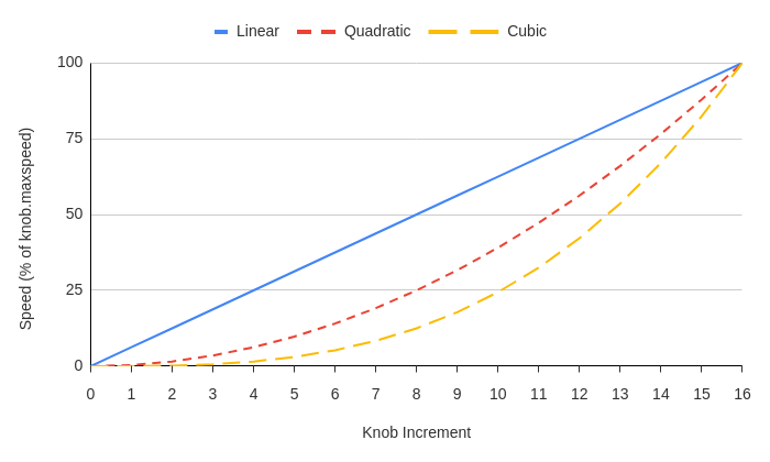
WR) warning flag is set), the speed achievable with the knob is limited to the minimum of limit.approach.maxspeed and knob.maxspeed. lamp
These settings contain controls for, and information about, the lamp.
These settings are used on devices that control illumination.
See the lamp commands section for commands related to lamps.
lamp.current
The current to send to the lamp
- Valid Values
- 0 to lamp.current.max
- Scope
- Axis
- Write Access Level
- Normal
- Persistence
- Volatile
Controls the brightness of the lamp by specifying the current to provide to the lamp, in units of amps.
Writing lamp.current also modifies lamp.flux. The conversion between these values is specific to each lamp.
Introduced in 7.09
Example: Adjusting the brightness of the lamp
Configure the driver to provide 250 mA of current to the lamp:
/1 1 set lamp.current 0.25↵
@01 1 OK IDLE -- 0lamp.current.max
The maximum current the lamp can safely withstand
- Valid Values
- 0 to 3
- Scope
- Axis
- Write Access Level
- Read-only
- Persistence
- Non-volatile
Specifies the maximum current the lamp can safely withstand, in units of amps.
Introduced in 7.09
Example: Reading the maximum lamp current
/1 1 get lamp.current.max↵
@01 1 OK IDLE -- 1.000This lamp supports up to 1 A.
lamp.flux
The radiant flux to emit from the lamp
- Valid Values
- 0 to lamp.flux.max
- Scope
- Axis
- Write Access Level
- Normal
- Persistence
- Volatile
Controls the brightness of the lamp by specifying the radiant flux to emit from the lamp, in units of watts.
Writing lamp.flux also modifies lamp.current. The conversion between these values is specific to each lamp.
Introduced in 7.09
Example: Adjusting the brightness of the lamp
Configure the lamp to emit 1.5 W of radiant flux:
/1 1 set lamp.flux 1.5↵
@01 1 OK IDLE -- 0lamp.flux.max
The maximum flux the lamp can emit
- Valid Values
- 0 to 10
- Scope
- Axis
- Write Access Level
- Read-only
- Persistence
- Non-volatile
Specifies the maximum radiant flux the lamp can emit, in units of watts.
Introduced in 7.09
Example: Reading the maximum flux
/1 1 get lamp.flux.max↵
@01 1 OK IDLE -- 10.000This lamp can emit up to 10 W of radiant flux.
lamp.status
The lamp status
- Valid Values
-
- 0
-
Unplugged
- 1
-
Turned Off
- 2
-
Turned On
- 3
-
Fault
A fault has occurred and the lamp has been disabled
- 4
-
Not Usable
This lamp is not supported by this firmware version
- 5
-
Peripheral Not Connected
The peripheral indicated by peripheral.id is not connected to the controller
- Scope
- Axis
- Write Access Level
- Read-only
- Persistence
- Volatile
Specifies the status of the lamp.
Introduced in 7.09
Example: Reading the status of the lamp
/1 1 get lamp.status↵
@01 1 OK IDLE -- 2The lamp is turned on.
lamp.temperature
The lamp temperature
- Valid Values
- -173.7 to 605.4
- Scope
- Axis
- Write Access Level
- Read-only
- Persistence
- Volatile
Specifies the temperature of the lamp, in units of degrees Celsius.
The Temperature High (WT) warning flag is set if the lamp is approaching its temperature limit. Once the lamp becomes too hot to guarantee normal operation, the lamp is disabled and the Driver Temperature/Current Error Driver Temperature/Current Error Driver Disabled (FD) warning flag is set.
Introduced in 7.09
Example: Reading the temperature of the lamp
/1 1 get lamp.temperature↵
@01 1 OK IDLE -- 53.5The lamp temperature is presently 53.5°C.
lamp.wavelength.fwhm
The full width at half maximum of the lamp
- Valid Values
- 0 to 1,000,000
- Scope
- Axis
- Write Access Level
- Read-only
- Persistence
- Non-volatile
Specifies the full width at half maximum of the lamp’s output spectrum, in units of nanometres.
For a white lamp, this setting is zero.
Introduced in 7.09
lamp.wavelength.peak
The peak wavelength produced by the lamp
- Valid Values
- 0 to 1,000,000
- Scope
- Axis
- Write Access Level
- Read-only
- Persistence
- Non-volatile
Specifies the peak wavelength output by the lamp, in units of nanometres.
For a white lamp, this setting is zero.
Introduced in 7.09
limit
These settings contain controls for, and information about, the axis limits.
limit.approach.maxspeed
The maximum speed to use when there is no reference position
- Valid Values
- 0 to maxspeed.max
- Scope
- Axis
- Write Access Level
- Advanced
- Persistence
- Non-volatile
When the axis does not have a reference position (i.e., the No Reference Position (WR) warning flag is set), or during a home command, the axis travels at the lesser of limit.approach.maxspeed and maxspeed. To safely control fast-moving devices during homing, set limit.approach.maxspeed lower than maxspeed.
See the Physical Units section for information about unit conversions.
limit.away.action
The action taken when the away limit sensor becomes active
- Valid Values
-
- 0
-
Disabled
Take no action when the away sensor becomes active.
- 1
-
Retract
Retract to the side of the sensor.
- 2
-
Retract and update pos
Retract to the side of the sensor, write the value of limit.away.preset to pos, move to the position specified by limit.away.offset, and clear the No Reference Position (
WR) warning flag. - 3
-
Retract and update pos if not yet homed
If the No Reference Position (
WR) warning flag is set, retract and update pos then move to the position specified by limit.away.offset. Otherwise, ignore the sensor and take no action. - 4
-
Retract and update pos without offset
Retract to the side of the sensor, write the value of limit.away.preset to pos, and clear the No Reference Position (
WR) warning flag without performing any offset movement.Introduced in 7.27
- 5
-
Retract and update pos without offset if not yet homed
If the No Reference Position (
WR) warning flag is set, retract and update pos without performing any offset movement. Otherwise, ignore the sensor and take no action.Introduced in 7.27
- Scope
- Axis
- Write Access Level
- Advanced
- Persistence
- Non-volatile
Specifies the automatic action to perform when the axis activates the away sensor.
The away sensor is active when limit.away.state is 1.
If a limit action is triggered and the No Reference Position (WR) warning flag is not present, the Unexpected Limit Trigger (WL) warning flag is set since travel within the valid range of the axis should not ordinarily trigger limit sensors after the reference position is set.
If multiple limit sensors are present, at most one should be configured to update pos when the sensor activates. Otherwise, the value of pos could be inconsistent depending upon which sensor was most recently encountered.
The axis will retract to the side of the sensor specified by limit.away.edge.
Example: Selecting a value for a linear device
Suppose the device moves linearly between two limit sensors. Passing either sensor is not desirable, because the stage could collide with the end of its travel range. Both limit sensors should therefore use a limit action that will always retract the axis (even if the axis is homed), so that travel is always restricted between the sensors. The limit sensor which is being used as the position reference should use either 2 or 4 for its limit action, so that the position reference is kept up to date when the sensor is encountered. The other limit sensor should use 1 for its limit action, so that it will restrict travel without interfering with the position reference.
Example: Selecting a value for a rotary device
Suppose the device freely rotates and uses one limit sensor as the position reference. The device should be allowed to pass the limit sensor so that it can complete a full rotation. Therefore, the sensor should use 0 for its limit action. Homing will update the position reference as normal, but if the limit sensor is encountered in other circumstances, it will not restrict movement.
limit.away.edge
The side of the away sensor the axis aligns to during limit actions
- Valid Values
-
- 0
-
Positive edge
Align the axis with the positive side of the sensor.
- 1
-
Negative edge
Align the axis with the negative side of the sensor.
- Scope
- Axis
- Write Access Level
- Advanced
- Persistence
- Non-volatile
Specifies the side/edge of the away sensor to align with when the sensor is triggered.
The positive and negative edges follow the orientation of the axis. That is, the positive sensor edge is at a more positive position than the negative edge.

limit.away.offset
The offset distance moved at the end of away limit actions
- Valid Values
- −2,000,000,000 to 2,000,000,000
- Scope
- Axis
- Write Access Level
- Normal
- Persistence
- Non-volatile
Specifies the distance the axis will move when the away limit sensor is spontaneously encountered or at the end of tools gotolimit commands. The offset is relative to the limit.away.preset position and the move only occurs as part of some limit actions (specified by limit.away.action).
If limit.cycle.mode is set to Bounded and the movement would take the axis outside the range limit.min to limit.max, the axis will not move the specified offset, and the Limit Error (FE) warning flag will be set.
The movement is similar to a move rel issued from the limit.away.preset position except that in some cases (e.g., an axis that homes to an index mark) the axis may not need to first travel to the limit.away.preset position before moving to the offset position.
Introduced in 7.27
Example: Automatically moving a specific distance after encountering the away limit sensor
Configure the axis to move -200 position units from the away limit sensor after encountering the sensor:
/set limit.away.offset -200↵
@01 0 OK IDLE -- 0Sending /tools gotolimit away pos 2 0↵ will move the axis to find the away limit sensor, after which pos will equal limit.away.preset - 200.
Example: Automatically moving to a specific position after encountering the away limit sensor
Consider an axis that should move to the centre of travel after encountering the away limit sensor. Suppose limit.min is 0, limit.max is 125000, and limit.away.preset is 125000. Then the midpoint of travel is (125000 - 0) / 2 = 62500 and limit.away.offset should be set to midpoint - limit.away.preset = 62500 - 125000 = -62500:
/set limit.away.offset -62500↵
@01 0 OK IDLE -- 0Sending /tools gotolimit away pos 2 0↵ will move the axis to find the away limit sensor, after which pos will equal 62500.
limit.away.posupdate
The control for how limit.max is updated after a limit action
Depending on the value of this setting, the device may update the away sensor position (limit.max) after a limit action is complete. This setting has no effect if the limit action is disabled (limit.away.action is 0).
limit.away.preset
The value away limit actions write to pos
- Valid Values
- -1,000,000,000 to 1,000,000,000
- Scope
- Axis
- Write Access Level
- Advanced
- Persistence
- Non-volatile
The value written to pos after away limit actions (specified by limit.away.action). This occurs as part of the tools gotolimit command, or after triggering the away sensor.
See the Physical Units section for information about unit conversions.
limit.away.source
The source of the away limit sensor signal
- Valid Values
-
- 0
-
A digital sensor connected to the away pin
- 1
-
An encoder index pulse
- Scope
- Axis
- Write Access Level
- Advanced
- Persistence
- Non-volatile
Specifies where the away limit sensor signal comes from.
In order to use sources that require an encoder index pulse, ensure that the encoder specified by encoder.port.default is configured to use index pulses. See encoder.1.index.mode or encoder.2.index.mode.
In firmware versions 7.47 and above, a digital limit away port must be available on the axis in order to write this setting to a value other than 1.
limit.away.state
The current state of the away limit sensor
- Valid Values
-
- 0
-
Inactive
The sensor is not active.
- 1
-
Active
The sensor is active.
- Scope
- Axis
- Write Access Level
- Read-only
- Persistence
- Volatile
If no limit sensor is connected (i.e., limit.away.type is 0), this setting is always 0.
limit.away.triggered
Whether an action or command associated with the away sensor has completed
- Valid Values
-
- 0
-
No away action or command has completed.
- 1
-
An away action or command has completed.
- Scope
- Axis
- Write Access Level
- Read-only
- Persistence
- Volatile
On power-up this setting is set to 0. The setting is set to 1 after an away limit action or a limit sensor command completes.
Note that if limit.away.action is configured such that no action is taken when the limit sensor is active, this setting will only become 1 after a limit sensor command completes.
limit.away.tune
The tuning offset applied to the edge of the away limit sensor prior to applying limit.away.preset
- Valid Values
- −512,000,000,000 to 512,000,000,000
- Scope
- Axis
- Write Access Level
- Advanced
- Persistence
- Non-volatile
This setting allows the reference position of the away sensor to be adjusted. During limit actions, the axis will move the relative distance specified with this setting after detecting the relevant edge of the limit sensor and before writing limit.away.preset to pos. A positive value causes a move in the positive direction, and a negative value causes a move in the negative direction. The relevant edge is specified by limit.away.edge.
For all devices, one limit.away.tune unit is:
For stepper motor products, this is equivalent to one full step / 256. It is chosen this way to provide adequate precision while being independent of the resolution setting. For a resolution of 64, a value of 4 in this setting means add one microstep.
For direct-drive motor products, where resolution is set to one, the units of this setting are the units of pos / 256. A value of 256 in this setting means add one pos unit.
To compute the limit.away.tune setting given an equivalent distance in pos units, use the following equation:
Introduced in 7.06
limit.away.type
The signal type of the connected away sensor
- Valid Values
-
- 0
-
Disabled
No away sensor is connected.
- 1
-
Active Low
When active, the sensor outputs a logic low.
- 2
-
Active High
When active, the sensor outputs a logic high.
- Scope
- Axis
- Write Access Level
- Advanced
- Persistence
- Non-volatile
Specifies the type of logical signal the connected sensor outputs.
In firmware versions 7.47 and above, a digital limit away port must be available on the axis in order to write this setting to a value other than 0.
limit.away.width
An upper bound on the width of the away sensor signal
- Valid Values
- 0 to 2,000,000,000
- Scope
- Axis
- Write Access Level
- Advanced
- Persistence
- Non-volatile
The width, in position units, of the region where the away sensor can be active. When the sensor is first encountered, moving the distance specified by this setting should guarantee that the sensor is no longer active. Therefore, if it is possible for the away sensor to be active over a range of positions, this setting should be set to a value greater than the width of the active region. During limit detection, the outermost edge of the active region, as specified by limit.away.edge, defines the limit position.
limit.c.action
The action taken when the c limit sensor becomes active
- Valid Values
-
- 0
-
Disabled
Take no action when the c sensor becomes active.
- 1
-
Retract
Retract to the side of the sensor.
- 2
-
Retract and update pos
Retract to the side of the sensor, write the value of limit.c.preset to pos, move to the position specified by limit.c.offset, and clear the No Reference Position (
WR) warning flag. - 3
-
Retract and update pos if not yet homed
If the No Reference Position (
WR) warning flag is set, retract and update pos then move to the position specified by limit.c.offset. Otherwise, ignore the sensor and take no action. - 4
-
Retract and update pos without offset
Retract to the side of the sensor, write the value of limit.c.preset to pos, and clear the No Reference Position (
WR) warning flag without performing any offset movement.Introduced in 7.27
- 5
-
Retract and update pos without offset if not yet homed
If the No Reference Position (
WR) warning flag is set, retract and update pos without performing any offset movement. Otherwise, ignore the sensor and take no action.Introduced in 7.27
- Scope
- Axis
- Write Access Level
- Advanced
- Persistence
- Non-volatile
Specifies the automatic action to perform when the axis activates the c sensor.
The c sensor is active when limit.c.state is 1.
If a limit action is triggered and the No Reference Position (WR) warning flag is not present, the Unexpected Limit Trigger (WL) warning flag is set since travel within the valid range of the axis should not ordinarily trigger limit sensors after the reference position is set.
If multiple limit sensors are present, at most one should be configured to update pos when the sensor activates. Otherwise, the value of pos could be inconsistent depending upon which sensor was most recently encountered.
The axis will retract to the side of the sensor specified by limit.c.edge.
Example: Selecting a value for a linear device
Suppose the device moves linearly between two limit sensors. Passing either sensor is not desirable, because the stage could collide with the end of its travel range. Both limit sensors should therefore use a limit action that will always retract the axis (even if the axis is homed), so that travel is always restricted between the sensors. The limit sensor which is being used as the position reference should use either 2 or 4 for its limit action, so that the position reference is kept up to date when the sensor is encountered. The other limit sensor should use 1 for its limit action, so that it will restrict travel without interfering with the position reference.
Example: Selecting a value for a rotary device
Suppose the device freely rotates and uses one limit sensor as the position reference. The device should be allowed to pass the limit sensor so that it can complete a full rotation. Therefore, the sensor should use 0 for its limit action. Homing will update the position reference as normal, but if the limit sensor is encountered in other circumstances, it will not restrict movement.
limit.c.edge
The side of the c sensor the axis aligns to during limit actions
- Valid Values
-
- 0
-
Positive edge
Align the axis with the positive side of the sensor.
- 1
-
Negative edge
Align the axis with the negative side of the sensor.
- Scope
- Axis
- Write Access Level
- Advanced
- Persistence
- Non-volatile
Specifies the side/edge of the c sensor to align with when the sensor is triggered.
The positive and negative edges follow the orientation of the axis. That is, the positive sensor edge is at a more positive position than the negative edge.
limit.c.offset
The offset distance moved at the end of c limit actions
- Valid Values
- −2,000,000,000 to 2,000,000,000
- Scope
- Axis
- Write Access Level
- Normal
- Persistence
- Non-volatile
Specifies the distance the axis will move when the c limit sensor is spontaneously encountered or at the end of tools gotolimit commands. The offset is relative to the limit.c.preset position and the move only occurs as part of some limit actions (specified by limit.c.action).
If limit.cycle.mode is set to Bounded and the movement would take the axis outside the range limit.min to limit.max, the axis will not move the specified offset, and the Limit Error (FE) warning flag will be set.
The movement is similar to a move rel issued from the limit.c.preset position except that in some cases (e.g., an axis that homes to an index mark) the axis may not need to first travel to the limit.c.preset position before moving to the offset position.
Introduced in 7.27
Example: Automatically moving a specific distance after encountering the c limit sensor
Configure the axis to move 200 position units from the c limit sensor after encountering the sensor:
/set limit.c.offset 200↵
@01 0 OK IDLE -- 0Sending /tools gotolimit c neg 2 0↵ will move the axis to find the c limit sensor, after which pos will equal limit.c.preset + 200.
Example: Automatically moving to a specific position after encountering the c limit sensor
Consider an axis that should move to the centre of travel after encountering the c limit sensor. Suppose limit.min is 0, limit.max is 125000, and limit.c.preset is 30000. Then the midpoint of travel is (125000 - 0) / 2 = 62500 and limit.c.offset should be set to midpoint - limit.c.preset = 62500 - 30000 = 32500:
/set limit.c.offset 32500↵
@01 0 OK IDLE -- 0Sending /tools gotolimit c neg 2 0↵ will move the axis to find the c limit sensor, after which pos will equal 62500.
limit.c.pos
The position of the c sensor
- Valid Values
- -1,000,000,000 to 1,000,000,000
- Scope
- Axis
- Write Access Level
- Read-only
- Persistence
- Non-volatile
The position of the c sensor. Depending on the value of limit.c.posupdate, it may be automatically updated to the current position of the sensor as part of a limit action.
See the Physical Units section for information about unit conversions.
limit.c.posupdate
The control for how limit.c.pos is updated after a limit action
- Valid Values
-
- 0
-
Disabled
Do not update limit.c.pos.
- 1
-
Set to current position
Write the current position (pos) to limit.c.pos.
- 2
-
Set to current position and save
Write the current position (pos) to limit.c.pos and save it to non-volatile memory so that it persists after the next power-up.
- Scope
- Axis
- Write Access Level
- Advanced
- Persistence
- Non-volatile
Depending on the value of this setting, the device may update the c sensor position (limit.c.pos) after a limit action is complete. This setting has no effect if the limit action is disabled (limit.c.action is 0).
limit.c.preset
The value c limit actions write to pos
- Valid Values
- -1,000,000,000 to 1,000,000,000
- Scope
- Axis
- Write Access Level
- Advanced
- Persistence
- Non-volatile
The value written to pos after c limit actions (specified by limit.c.action). This occurs as part of the tools gotolimit command, or after triggering the c sensor.
See the Physical Units section for information about unit conversions.
limit.c.source
The source of the c limit sensor signal
- Valid Values
-
- 0
-
A digital sensor connected to the c pin
- 1
-
An encoder index pulse
- Scope
- Axis
- Write Access Level
- Advanced
- Persistence
- Non-volatile
Specifies where the c limit sensor signal comes from.
In order to use sources that require an encoder index pulse, ensure that the encoder specified by encoder.port.default is configured to use index pulses. See encoder.1.index.mode or encoder.2.index.mode.
In firmware versions 7.47 and above, a digital limit c port must be available on the axis in order to write this setting to a value other than 1.
limit.c.state
The current state of the c limit sensor
- Valid Values
-
- 0
-
Inactive
The sensor is not active.
- 1
-
Active
The sensor is active.
- Scope
- Axis
- Write Access Level
- Read-only
- Persistence
- Volatile
If no limit sensor is connected (i.e., limit.c.type is 0), this setting is always 0.
limit.c.triggered
Whether an action or command associated with the c sensor has completed
- Valid Values
-
- 0
-
No c action or command has completed.
- 1
-
A c action or command has completed.
- Scope
- Axis
- Write Access Level
- Read-only
- Persistence
- Volatile
On power-up this setting is set to 0. The setting is set to 1 after a c limit action or a limit sensor command completes.
Note that if limit.c.action is configured such that no action is taken when the limit sensor is active, this setting will only become 1 after a limit sensor command completes.
limit.c.tune
The tuning offset applied to the edge of the c limit sensor prior to applying limit.c.preset
- Valid Values
- −512,000,000,000 to 512,000,000,000
- Scope
- Axis
- Write Access Level
- Advanced
- Persistence
- Non-volatile
This setting allows the reference position of the c sensor to be adjusted. During limit actions, the axis will move the relative distance specified with this setting after detecting the relevant edge of the limit sensor and before writing limit.c.preset to pos. A positive value causes a move in the positive direction, and a negative value causes a move in the negative direction. The relevant edge is specified by limit.c.edge.
For all devices, one limit.c.tune unit is:
For stepper motor products, this is equivalent to one full step / 256. It is chosen this way to provide adequate precision while being independent of the resolution setting. For a resolution of 64, a value of 4 in this setting means add one microstep.
For direct-drive motor products, where resolution is set to one, the units of this setting are the units of pos / 256. A value of 256 in this setting means add one pos unit.
To compute the limit.c.tune setting given an equivalent distance in pos units, use the following equation:
Introduced in 7.06
limit.c.type
The signal type of the connected c sensor
- Valid Values
-
- 0
-
Disabled
No c sensor is connected.
- 1
-
Active Low
When active, the sensor outputs a logic low.
- 2
-
Active High
When active, the sensor outputs a logic high.
- Scope
- Axis
- Write Access Level
- Advanced
- Persistence
- Non-volatile
Specifies the type of logical signal the connected sensor outputs.
In firmware versions 7.47 and above, a digital limit c port must be available on the axis in order to write this setting to a value other than 0.
limit.c.width
An upper bound on the width of the c sensor signal
- Valid Values
- 0 to 2,000,000,000
- Scope
- Axis
- Write Access Level
- Advanced
- Persistence
- Non-volatile
The width, in position units, of the region where the c sensor can be active. When the sensor is first encountered, moving the distance specified by this setting should guarantee that the sensor is no longer active. Therefore, if it is possible for the c sensor to be active over a range of positions, this setting should be set to a value greater than the width of the active region. During limit detection, the outermost edge of the active region, as specified by limit.c.edge, defines the limit position.
limit.cycle.dist
The size of one full rotation of the device
- Valid Values
-
0 to 1,000,000,000 (versions 7.47 and above)
0 to 2,000,000,000 (versions 7.46 and below)
- Scope
- Axis
- Write Access Level
- Advanced
- Persistence
- Non-volatile
The distance the rotary axis needs to move to complete one full rotation. On stepper motor products, this distance is measured in microsteps per rotation, so it is affected by resolution (which for most stepper motor devices is 64 by default), the number of steps per one revolution of the motor, and any mechanical gearing that changes the relationship between motor rotations and device rotations. On servo motor products, this distance is measured in encoder counts per rotation, so it is affected by any mechanical gearing that changes the relationship between motor rotations and device rotations.
A value of 0 indicates that the device is not capable of completing a full rotation of motion.
See the Physical Units section for information about unit conversions.
Example: Calculating limit.cycle.dist
Suppose a stepper motor has 200 steps per revolution, and the resolution setting is set to 64. There is mechanical gearing such that it takes five rotations of the motor for the device to complete a rotation. Then limit.cycle.dist should be set to:
limit.cycle.mode
Enable infinite motion on a cyclic axis
- Valid Values
-
- 1
-
Cyclic
Position wraps with each cycle, enabling infinite motion
- Scope
- Axis
- Write Access Level
- Normal
- Persistence
- Non-volatile
Specifies the limit cycle mode of the axis.
If the limit cycle mode is bounded, the value of pos represents the total travelled distance from some fixed reference position (e.g., the home position). In this mode, the range of motion is bounded by the position constraints limit.min and limit.max.
If the limit cycle mode is cyclic, the value of pos no longer represents the total distance but instead the distance within the current cycle. The distance is measured in the positive direction and the size of the cycle is defined by limit.cycle.dist. As a result, pos always falls in the range 0 to limit.cycle.dist - 1 (the wrapping range) and differs from the total travelled distance by an integer multiple of limit.cycle.dist. In this mode, the pos.cycles setting can be used to track the total distance travelled (in units of cycles) from a fixed reference position. Other position settings such as encoder.pos are always expressed in the same reference frame as pos. As a result, they may also experience abrupt changes when the axis undergoes a position-wrapping event. These changes do not impact smoothness of motion or control.
The following figure illustrates the difference in how pos is measured in each of the two modes as it completes cycles in both the positive and negative directions.
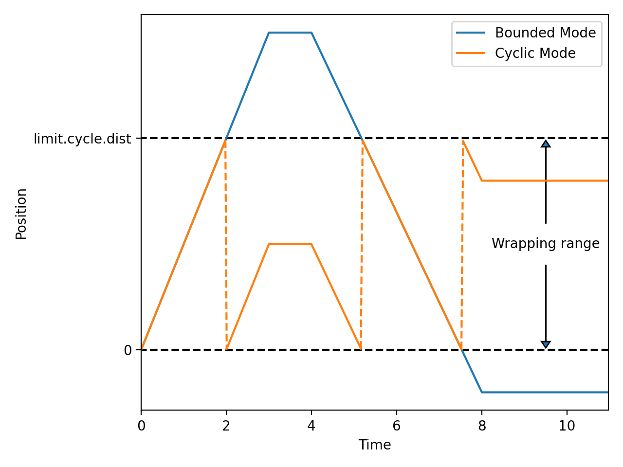
- In cyclic mode, limit.min and limit.max are not respected even if they are inside the wrapping range
- In cyclic mode, absolute move commands such as move abs and move stored only accept targets inside the wrapping range
- In cyclic mode, move min|max and move vel produce infinite motion
Introduced in 7.47
Example: Cross a wrap point in cyclic mode
Cross the positive and negative wrap points in cyclic mode and verify that position remains inside the wrapping range. The axis has a cycle distance of 360.
/set limit.cycle.mode 1↵
@01 0 OK IDLE -- 0
/get pos↵
@01 0 OK BUSY -- 0
/move rel 540↵
@01 0 OK BUSY -- 0
/get pos↵
@01 0 OK BUSY -- 180
/move rel -360↵
@01 0 OK BUSY -- 0
/get pos↵
@01 0 OK BUSY -- 180limit.detect.decelonly
The deceleration to use when stopping after a limit sensor has been triggered
- Valid Values
- 0 to 2,147,483,647
- Scope
- Axis
- Write Access Level
- Advanced
- Persistence
- Non-volatile
When a limit sensor is triggered, the axis slows down to a stop at this rate. A value of 0 specifies that the axis should stop immediately.
See the Physical Units section for information about unit conversions.
limit.detect.maxspeed
The maximum speed used when aligning with the edge of a limit sensor
- Valid Values
- 0 to maxspeed.max
- Scope
- Axis
- Write Access Level
- Advanced
- Persistence
- Non-volatile
After a limit sensor is triggered and the axis has stopped, it determines the precise edge of the sensor by moving away from the sensor at this speed.
See the Physical Units section for information about unit conversions.
limit.hardstop.retraction
The distance the axis retracts after reaching a mechanical hardstop
- Valid Values
- 0 to 2,000,000,000
- Scope
- Axis
- Write Access Level
- Normal
- Persistence
- Non-volatile
This setting is only used when retracting from mechanical hardstops in the tools gotolimit hardstop and tools findrange hardstop commands. The axis will not retract after encountering a hardstop in any other context.
Introduced in 7.39
limit.home.action
The action taken when the home limit sensor becomes active
- Valid Values
-
- 0
-
Disabled
Take no action when the home sensor becomes active.
- 1
-
Retract
Retract to the side of the sensor.
- 2
-
Retract and update pos
Retract to the side of the sensor, write the value of limit.home.preset to pos, move to the position specified by limit.home.offset, and clear the No Reference Position (
WR) warning flag. - 3
-
Retract and update pos if not yet homed
If the No Reference Position (
WR) warning flag is set, retract and update pos then move to the position specified by limit.home.offset. Otherwise, ignore the sensor and take no action. - 4
-
Retract and update pos without offset
Retract to the side of the sensor, write the value of limit.home.preset to pos, and clear the No Reference Position (
WR) warning flag without performing any offset movement.Introduced in 7.27
- 5
-
Retract and update pos without offset if not yet homed
If the No Reference Position (
WR) warning flag is set, retract and update pos without performing any offset movement. Otherwise, ignore the sensor and take no action.Introduced in 7.27
- Scope
- Axis
- Write Access Level
- Advanced
- Persistence
- Non-volatile
Specifies the automatic action to perform when the axis activates the home sensor.
The home sensor is active when limit.home.state is 1.
If a limit action is triggered and the No Reference Position (WR) warning flag is not present, the Unexpected Limit Trigger (WL) warning flag is set since travel within the valid range of the axis should not ordinarily trigger limit sensors after the reference position is set.
If multiple limit sensors are present, at most one should be configured to update pos when the sensor activates. Otherwise, the value of pos could be inconsistent depending upon which sensor was most recently encountered.
The axis will retract to the side of the sensor specified by limit.home.edge.
Example: Selecting a value for a linear device
Suppose the device moves linearly between two limit sensors. Passing either sensor is not desirable, because the stage could collide with the end of its travel range. Both limit sensors should therefore use a limit action that will always retract the axis (even if the axis is homed), so that travel is always restricted between the sensors. The limit sensor which is being used as the position reference should use either 2 or 4 for its limit action, so that the position reference is kept up to date when the sensor is encountered. The other limit sensor should use 1 for its limit action, so that it will restrict travel without interfering with the position reference.
Example: Selecting a value for a rotary device
Suppose the device freely rotates and uses one limit sensor as the position reference. The device should be allowed to pass the limit sensor so that it can complete a full rotation. Therefore, the sensor should use 0 for its limit action. Homing will update the position reference as normal, but if the limit sensor is encountered in other circumstances, it will not restrict movement.
limit.home.bidirectional
Whether to search for the home sensor in two directions when homing
- Valid Values
-
- 0
- Search for the home sensor only in the negative direction
- 1
- Search for the home sensor in the negative and positive directions
- Scope
- Axis
- Write Access Level
- Advanced
- Persistence
- Non-volatile
Specifies whether the axis should search for the home sensor in only the negative direction or in both the negative and positive directions when homing. When set to 1, if the axis stalls while searching for the home sensor in the negative direction, it will assume that it has reached the end of travel, turn around, and search for the home sensor in the positive direction.
On a linear device, if it is possible for the axis to be on either side of the home sensor when homing, limit.home.bidirectional should be 1.
On a rotary device, if the axis can rotate indefinitely, it should always be possible to find the home sensor by searching in the negative direction. Therefore, limit.home.bidirectional should be 0. If the axis cannot rotate 360°, limit.home.bidirectional should be 1.
Introduced in 7.20
limit.home.edge
The side of the home sensor the axis aligns to during limit actions
- Valid Values
-
- 0
-
Positive edge
Align the axis with the positive side of the sensor.
- 1
-
Negative edge
Align the axis with the negative side of the sensor.
- Scope
- Axis
- Write Access Level
- Advanced
- Persistence
- Non-volatile
Specifies the side/edge of the home sensor to align with when the sensor is triggered.
The positive and negative edges follow the orientation of the axis. That is, the positive sensor edge is at a more positive position than the negative edge.
limit.home.offset
The offset distance moved at the end of home limit actions
- Valid Values
- −2,000,000,000 to 2,000,000,000
- Scope
- Axis
- Write Access Level
- Normal
- Persistence
- Non-volatile
Specifies the distance the axis will move when the home limit sensor is spontaneously encountered or at the end of home and tools gotolimit commands. The offset is relative to the limit.home.preset position and the move only occurs as part of some limit actions (specified by limit.home.action).
If limit.cycle.mode is set to Bounded and the movement would take the axis outside the range limit.min to limit.max, the axis will not move the specified offset, and the Limit Error (FE) warning flag will be set.
The movement is similar to a move rel issued from the limit.home.preset position except that in some cases (e.g., an axis that homes to an index mark) the axis may not need to first travel to the limit.home.preset position before moving to the offset position.
Introduced in 7.27
Example: Automatically moving a specific distance after encountering the home limit sensor
Configure the axis to move 200 position units from the home limit sensor after encountering the sensor:
/set limit.home.offset 200↵
@01 0 OK IDLE -- 0Sending /tools gotolimit home neg 2 0↵ or home with an appropriate value for limit.home.action will move the axis to find the home limit sensor, after which pos will equal limit.home.preset + 200.
Example: Automatically moving to a specific position after encountering the home limit sensor
Consider an axis that should move to the centre of travel after encountering the home limit sensor. Suppose limit.min is 0, limit.max is 125000, and limit.home.preset is 500. Then the midpoint of travel is (125000 - 0) / 2 = 62500 and limit.home.offset should be set to midpoint - limit.home.preset = 62500 - 500 = 62000:
/set limit.home.offset 62000↵
@01 0 OK IDLE -- 0Sending /tools gotolimit home neg 2 0↵ or home with an appropriate value for limit.home.action will move the axis to find the home limit sensor, after which pos will equal 62500.
limit.home.posupdate
The control for how limit.min is updated after a limit action
Depending on the value of this setting, the device may update the home sensor position (limit.min) after a limit action is complete. This setting has no effect if the limit action is disabled (limit.home.action is 0).
limit.home.preset
The value home limit actions write to pos
- Valid Values
- -1,000,000,000 to 1,000,000,000
- Scope
- Axis
- Write Access Level
- Advanced
- Persistence
- Non-volatile
The value written to pos after home limit actions (specified by limit.home.action). This occurs as part of the home command, the tools gotolimit command, or after triggering the home sensor.
See the Physical Units section for information about unit conversions.
limit.home.source
The source of the home limit sensor signal
- Valid Values
-
- 0
-
A digital sensor connected to the home pin
- 1
-
An encoder index pulse
- 2
-
Both a digital sensor connected to the home pin and a non-repeating encoder index pulse
- Scope
- Axis
- Write Access Level
- Advanced
- Persistence
- Non-volatile
Specifies where the home limit sensor signal comes from.
When set to 2, the encoder index pulse provides the reference position and the digital sensor acts as a limit sensor. If the axis encounters the digital sensor before the encoder index pulse the axis will reverse away from the digital sensor to find the encoder index pulse. The action configured in limit.home.action is triggered if either the digital sensor or encoder index pulse is triggered.
In order to use sources that require an encoder index pulse, ensure that the encoder specified by encoder.port.default is configured to use index pulses. See encoder.1.index.mode or encoder.2.index.mode.
In firmware versions 7.47 and above, a digital limit home port must be available on the axis in order to write this setting to a value other than 1.
limit.home.state
The current state of the home limit sensor
- Valid Values
-
- 0
-
Inactive
The sensor is not active.
- 1
-
Active
The sensor is active.
- Scope
- Axis
- Write Access Level
- Read-only
- Persistence
- Volatile
If no limit sensor is connected (i.e., limit.home.type is 0), this setting is always 0.
limit.home.triggered
Whether an action or command associated with the home sensor has completed
- Valid Values
-
- 0
-
No home action or command has completed.
- 1
-
A home action or command has completed.
- Scope
- Axis
- Write Access Level
- Read-only
- Persistence
- Volatile
On power-up this setting is set to 0. The setting is set to 1 after a home limit action or a limit sensor command (such as the home command) completes.
Note that if limit.home.action is configured such that no action is taken when the limit sensor is active, this setting will only become 1 after a limit sensor command completes.
limit.home.tune
The tuning offset applied to the edge of the home limit sensor prior to applying limit.home.preset
- Valid Values
- −512,000,000,000 to 512,000,000,000
- Scope
- Axis
- Write Access Level
- Advanced
- Persistence
- Non-volatile
This setting allows the reference position of the home sensor to be adjusted. During limit actions, the axis will move the relative distance specified with this setting after detecting the relevant edge of the limit sensor and before writing limit.home.preset to pos. A positive value causes a move in the positive direction, and a negative value causes a move in the negative direction. The relevant edge is specified by limit.home.edge.
For all devices, one limit.home.tune unit is:
For stepper motor products, this is equivalent to one full step / 256. It is chosen this way to provide adequate precision while being independent of the resolution setting. For a resolution of 64, a value of 4 in this setting means add one microstep.
For direct-drive motor products, where resolution is set to one, the units of this setting are the units of pos / 256. A value of 256 in this setting means add one pos unit.
To compute the limit.home.tune setting given an equivalent distance in pos units, use the following equation:
limit.home.type
The signal type of the connected home sensor
- Valid Values
-
- 0
-
Disabled
No home sensor is connected.
- 1
-
Active Low
When active, the sensor outputs a logic low.
- 2
-
Active High
When active, the sensor outputs a logic high.
- Scope
- Axis
- Write Access Level
- Advanced
- Persistence
- Non-volatile
Specifies the type of logical signal the connected sensor outputs.
In firmware versions 7.47 and above, a digital limit home port must be available on the axis in order to write this setting to a value other than 0.
limit.home.width
An upper bound on the width of the home sensor signal
- Valid Values
- 0 to 2,000,000,000
- Scope
- Axis
- Write Access Level
- Advanced
- Persistence
- Non-volatile
The width, in position units, of the region where the home sensor can be active. When the sensor is first encountered, moving the distance specified by this setting should guarantee that the sensor is no longer active. Therefore, if it is possible for the home sensor to be active over a range of positions, this setting should be set to a value greater than the width of the active region. During limit detection, the outermost edge of the active region, as specified by limit.home.edge, defines the limit position.
limit.max
The maximum position the axis can move to
- Valid Values
- -1,000,000,000 to 1,000,000,000
- Scope
- Axis
- Write Access Level
- Normal
- Persistence
- Non-volatile
The maximum position the axis can move to. The range of travel (limit.min to limit.max) is different for each product.
Depending on the value of limit.away.posupdate, limit.max may be automatically updated to the current position of the away sensor, if it exists, as part of a limit action.
limit.max is only respected when limit.cycle.mode is set to Bounded.
See the Physical Units section for information about unit conversions.
limit.min
The minimum position the axis can move to
- Valid Values
- -1,000,000,000 to 1,000,000,000
- Scope
- Axis
- Write Access Level
- Normal
- Persistence
- Non-volatile
The minimum position the axis can move to. The range of travel (limit.min to limit.max) is different for each product.
Depending on the value of limit.home.posupdate, it may be automatically updated to the current position of the home sensor as part of a limit action.
limit.min is only respected when limit.cycle.mode is set to Bounded.
See the Physical Units section for information about unit conversions.
limit.range.mode
The control for whether the travel range is considered limited or infinite
- Valid Values
-
- 0
- Finite travel
- 1
- Infinite travel
- Scope
- Axis
- Write Access Level
- Advanced
- Persistence
- Non-volatile
Specifies how the controller interprets the travel range of the axis. Products with definite start and end positions (e.g., linear stages) have finite travel. Conversely, products that can move indefinitely in one direction (e.g., cyclic rotary stages) have infinite travel.
Although infinite travel products can physically move indefinitely in one direction, the controller cannot track infinitely large positions and enforces limits on pos. When these limits are reached the axis will stop. To circumvent these limitations and achieve infinite rotation, set limit.cycle.mode to Cyclic.
Introduced in 7.20
limit.ref.phase
The expected motor phase at the index mark
- Valid Values
- 0 to 65,535
- Scope
- Axis
- Write Access Level
- Normal
- Persistence
- Non-volatile
The expected motor phase at the index mark. During homing the applied motor phase at the index mark is compared to this value; if there is a large difference between limit.ref.phase and the applied motor phase then homing fails. If homing succeeds, the internal position is adjusted such that the phase associated with the index position is equal to limit.ref.phase.
Introduced in 7.05
limit.ref.phase.measured
The motor phase measured at the index mark
- Valid Values
- 0 to 65,535
- Scope
- Axis
- Write Access Level
- Read-only
- Persistence
- Volatile
The most recent measurement of the motor phase at the index mark. To populate this setting send the home measure phase command. A value of 65,535 indicates that the motor phase has not been measured or is otherwise invalid. This value is not used internally by firmware, but should be used to find an appropriate value for limit.ref.phase (which is the value used by homing).
Introduced in 7.05
limit.start.pos
The power-up value of pos
This setting determines the value of pos after powering up the axis.
See the Physical Units section for information about unit conversions.
lockstep.numgroups
The number of lockstep groups
- Valid Values
- 0 to 2
- Scope
- Device
- Write Access Level
- Read-only
- Persistence
- Non-volatile
The number of lockstep groups that can be activated simultaneously. Use lockstep setup enable to setup a lockstep group.
Introduced in 7.11
maxspeed
These settings contain controls related to the maximum speed of the axis.
maxspeed
The maximum speed the axis moves at
- Valid Values
- 1 to maxspeed.max
- Scope
- Axis
- Write Access Level
- Normal
- Persistence
- Non-volatile
When a movement command is issued, the axis accelerates up to and travels at this speed. If a movement command explicitly specifies a speed for the motion (for instance, move vel), maxspeed is ignored, and the axis travels at the speed specified in the command. During a home command, as well as anytime there is no reference position (i.e., the No Reference Position (WR) warning flag is set), the axis travels at the lesser of limit.approach.maxspeed and maxspeed.
If maxspeed is changed while the axis is moving, the axis will immediately apply the new speed and continue to move to the target position.
See the Physical Units section for information about unit conversions.
maxspeed.max
The maximum permitted speed of the axis
- Valid Values
- 1 to 4,294,967,295
- Scope
- Axis
- Write Access Level
- Read-only
- Persistence
- Non-volatile
The maximum speed permitted for the axis. The purpose of this setting is to provide an upper bound for other settings and command parameters; it does not necessarily describe what operating speed is safe for the axis. Consult the User Manual to learn more about what operating speeds are safe on a given product.
See the Physical Units section for information about unit conversions.
Introduced in 7.47
motion
These settings contain miscellaneous controls and information relating to the motion of the device that are not covered elsewhere.
motion.accelonly
The acceleration used when increasing speed
- Valid Values
- 0 to 2,147,483,647
- Scope
- Axis
- Write Access Level
- Normal
- Persistence
- Non-volatile
Specifies the acceleration used for most motion trajectories. The deceleration is set separately using motion.decelonly. The accel setting and motion.accelonly setting have the same value. If the accel setting is changed, the motion.accelonly setting is also updated.
See the Physical Units section for information about unit conversions.
motion.accel.ramptime
The size of the trajectory averaging window for motion smoothing
- Valid Values
- 0 to 50.0
- Scope
- Axis
- Write Access Level
- Normal
- Persistence
- Non-volatile
The size, in units of milliseconds and to one decimal place, of the averaging window applied to the motion trajectory.
A value of 0.0 or 0.1 will disable trajectory averaging.
Using this setting the controller applies a moving average filter to the commanded trajectory, smoothing the motion profile, and limiting jerk (the 3rd derivative of position). Motion smoothing can help minimize vibration, audible noise, and impact loading during acceleration and deceleration. This is particularly relevant to applications with low system stiffness, such as liquid payloads, belt drive actuators, or non-rigid mounting surfaces. It can also be useful to improve drive lifetime for applications with many rapid starts and stops. Higher values increase the averaging time span and amount of smoothing, at the cost of longer trajectory execution time. For given maximum acceleration and speed limits, motion.accel.ramptime will increase the trajectory execution time by the value of the setting in milliseconds.

The relationship between motion.accel.ramptime, motion.accelonly, motion.decelonly, and the achieved value of jerk depends on the shape of the given trajectory.
Typically, a trajectory consists of 3 segments: constant acceleration (defined by motion.accelonly), followed by constant velocity (defined by maxspeed), then constant deceleration (defined by motion.decelonly) to a stop, forming a trapezoidal velocity profile. If the averaging window size, motion.accel.ramptime, is shorter than the duration of each of the three segments then the jerk will be limited to:
For short movements, where maxspeed is either not reached or reached for a shorter time than motion.accel.ramptime, the jerk will be limited to:
See the Physical Units section for information about unit conversions.
Introduced in 7.19
motion.busy
Whether an axis is BUSY
- Valid Values
-
- 0
-
The axis is
IDLE - 1
-
The axis is
BUSY
- Scope
- Axis
- Write Access Level
- Read-only
- Persistence
- Volatile
Specifies whether an axis is BUSY.
See Status for a description of when an axis is BUSY.
motion.decelonly
The deceleration used when decreasing speed
- Valid Values
- 0 to 2,147,483,647
- Scope
- Axis
- Write Access Level
- Normal
- Persistence
- Non-volatile
Specifies the deceleration used for most motion trajectories. The acceleration is set separately using motion.accelonly. If the accel setting is changed, the motion.decelonly setting is updated to the same value.
See the Physical Units section for information about unit conversions.
motion.index.dist
The distance between consecutive index positions
- Valid Values
- 1 to 2,000,000,000
- Scope
- Axis
- Write Access Level
- Normal
- Persistence
- Non-volatile
The distance between positions reachable with the move index command.
For devices with a non-zero limit.cycle.dist, motion.index.dist should be set to less than limit.cycle.dist for move index commands to be accepted.
For linear devices, motion.index.dist should be less than or equal to limit.max and limit.max should be positive for move index commands to be accepted.
See the Physical Units section for information about unit conversions.
motion.index.num
The current index number
- Valid Values
- 0 to 2,147,483,647
- Scope
- Axis
- Write Access Level
- Read-only
- Persistence
- Volatile
If the current position is an index position, the index number will be returned, calculated as pos / motion.index.dist + 1. If pos is not a multiple of motion.index.dist, this setting will return 0.
For devices with a non-zero limit.cycle.dist, the index number wraps around (i.e., a pos of x and a pos of x + limit.cycle.dist will both return the same index number).
For linear devices, if pos is negative, this setting will return 0.
motion.tracking.ai
The analog input signal to track during a move track command
- Valid Values
- 1 to the value returned by io info ai
- Scope
- Axis
- Write Access Level
- Normal
- Persistence
- Non-volatile
Specifies which analog input channel to use as the input to the move track control loop.
Introduced in 7.40
motion.tracking.dir
The direction of the feedback control action during a move track command
- Valid Values
-
- 0
-
Not inverted
- 1
-
Inverted
- Scope
- Axis
- Write Access Level
- Normal
- Persistence
- Non-volatile
Specifies the direction of the feedback control action during a move track command.
When the direction of the feedback control action is 0 (not inverted) the position change will be positive when the analog input error is positive. Conversely, when the direction of the feedback control action is 1 (inverted) the position change will be negative when the analog input error is positive.
See the move track command for the definition of analog input error.
Introduced in 7.40
motion.tracking.ki
The integral gain term used during a move track command
- Valid Values
- 0 to 18,446,744,073.709551615
- Scope
- Axis
- Write Access Level
- Normal
- Persistence
- Non-volatile
The integral gain coefficient of the control loop used during a move track command.
This setting has nine decimal places and can be converted to units of pos/(s·mV) with:
See the Physical Units section for information about unit conversions.
Introduced in 7.40
motion.tracking.kp
The proportional gain term used during a move track command
- Valid Values
- 0 to 18,446,744,073.709551615
- Scope
- Axis
- Write Access Level
- Normal
- Persistence
- Non-volatile
The proportional gain coefficient of the control loop used during a motion tracking command.
This setting has nine decimal places and can be converted to units of pos/mV with:
See the Physical Units section for information about unit conversions.
Introduced in 7.40
motion.tracking.limit.max
The maximum position the axis can move to during a move track command
- Valid Values
- -1,000,000,000 to 1,000,000,000
- Scope
- Axis
- Write Access Level
- Normal
- Persistence
- Non-volatile
The maximum position the axis can move to during a move track command. The more restrictive of motion.tracking.limit.max and limit.max will govern the actual maximum allowable position during a move track command.
See the Physical Units section for information about unit conversions.
Introduced in 7.40
motion.tracking.limit.min
The minimum position the axis can move to during a move track command
- Valid Values
- -1,000,000,000 to 1,000,000,000
- Scope
- Axis
- Write Access Level
- Normal
- Persistence
- Non-volatile
The minimum position the axis can move to during a move track command. The more restrictive of motion.tracking.limit.min and limit.min will govern the actual minimum allowable position during a move track command.
See the Physical Units section for information about unit conversions.
Introduced in 7.40
motion.tracking.mode
Whether to follow trajectory limits when tracking an analog input signal
- Valid Values
-
- 0
-
Ignore trajectory limits
- 1
-
Adhere to trajectory limits
- Scope
- Axis
- Write Access Level
- Normal
- Persistence
- Non-volatile
Specifies whether the trajectory limits are applied to the control loop during a move track command and the tracking stage of a move scan track once command. These trajectory limits include maxspeed, motion.accelonly, motion.decelonly and motion.accel.ramptime.
To maximize the bandwidth of the system this setting should be set to 0. If a system is particularly sensitive to speed, acceleration, or jerk this setting should be set to 1.
Introduced in 7.40
motion.tracking.scan.dir
The direction to move during the scanning stage of a move scan track once command
- Valid Values
-
- 0
-
Scan in the positive direction
- 1
-
Scan in the negative direction
- Scope
- Axis
- Write Access Level
- Normal
- Persistence
- Non-volatile
Specifies the movement direction of the scanning stage of the move scan track once command.
Introduced in 7.40
motion.tracking.scan.maxspeed
The maximum speed to move during the scanning stage of a move scan track once command
- Valid Values
- 0 to maxspeed.max
- Scope
- Axis
- Write Access Level
- Normal
- Persistence
- Non-volatile
During the scanning stage of a move scan track once, when the axis is scanning for the range of travel where the analog input signal is within tolerance, the axis will move at the minimum of this speed and maxspeed.
Introduced in 7.40
motion.tracking.scan.offset
The distance to move during the offset stage of a move scan track once command
- Valid Values
- -2,000,000,000 to 2,000,000,000
- Scope
- Axis
- Write Access Level
- Normal
- Persistence
- Non-volatile
During the offset stage of a move scan track once command the axis will move this distance in the direction of motion.tracking.scan.dir before engaging the control loop.
Introduced in 7.40
motion.tracking.scan.period
The duration the analog input error must be within tolerance during the scanning stage of a move scan track once command
- Valid Values
- 0 to 429,496,729.5
- Scope
- Axis
- Write Access Level
- Normal
- Persistence
- Non-volatile
Specifies how long, in units of milliseconds and to one decimal place, the analog input error must be within the tolerance defined by motion.tracking.scan.tolerance before transitioning to the tracking stage of a move scan track once command.
See the move track command for the definition of analog input error.
Introduced in 7.40
motion.tracking.scan.signal.valid.delay
The duration the analog input signal must be valid for during a move scan track once command
- Valid Values
- 0 to 429,496,729.5
- Scope
- Axis
- Write Access Level
- Normal
- Persistence
- Non-volatile
Specifies how long, in units of milliseconds and to one decimal place, the digital input specified by motion.tracking.signal.valid.di must indicate that the motion.tracking.ai analog input is valid during the scanning stage of a move scan track once command before the analog signal is considered valid.
Introduced in 7.40
motion.tracking.scan.tolerance
The maximum analog input error accepted during the scanning stage of a move scan track once command
- Valid Values
- 0 to 65.535
- Scope
- Axis
- Write Access Level
- Normal
- Persistence
- Non-volatile
Specifies the tolerance, in units of volts and to three decimal places, that the analog input error must be within for the period defined by motion.tracking.scan.period in order for the axis to transition to the tracking stage of a move scan track once command.
Increasing this value reduces the time required to transition to the tracking stage of a move scan track once command but can also decrease repeatability.
See the move track command for the definition of analog input error.
Introduced in 7.40
motion.tracking.setpoint
The setpoint used during a move track command
- Valid Values
- -10.000 to 10.000
- Scope
- Axis
- Write Access Level
- Normal
- Persistence
- Non-volatile
The target value for the control loop that runs during the move track command, in units of volts and to three decimal places.
Introduced in 7.40
motion.tracking.settled
Whether the tracked analog input signal has settled
- Valid Values
-
- 0
-
Not settled
- 1
-
Settled
- Scope
- Axis
- Write Access Level
- Normal
- Persistence
- Volatile
This setting is automatically set to 0 at the beginning of move track and a move scan track once command. It can also be manually set to 0, but it cannot be manually set to 1.
If a move track once or move scan track once command finishes successfully this setting is set to 1 at the same time that the axis reports IDLE.
During a move track command run without the once parameter, which does not monitor for settling, this setting will never be set to 1.
Introduced in 7.40
motion.tracking.settle.mode
How settling is determined when tracking an analog input signal
- Valid Values
-
- 0
-
Monitor the analog input signal
- 1
-
Monitor the analog input signal and then the axis position
- 2
-
Monitor the analog input signal and axis position simultaneously
- Scope
- Axis
- Write Access Level
- Normal
- Persistence
- Non-volatile
Only the move track once command and the tracking stage of the move scan track once command use this setting.
If this setting is set to 0, the control loop waits for the analog input signal to settle. Once the analog input signal has settled according to motion.tracking.settle.period and motion.tracking.settle.tolerance the axis reports IDLE.
If this setting is set to 1, the control loop additionally waits for the axis position to settle after the analog input signal has settled. Once the analog input signal has settled according to the above criteria, the control loop waits for the axis position to settle according to cloop.settle.period and cloop.settle.tolerance, after which the axis reports IDLE. While the axis position is settling the control loop does not monitor the analog input signal.
If this setting is set to 2, the control loop waits for the analog input signal and axis position to settle together. Once the analog input signal and the axis position have settled simultaneously, according to the above criteria, the axis reports IDLE.
Introduced in 7.40
motion.tracking.settle.period
The duration the analog input error must be within tolerance to be considered settled during a move track once command
- Valid Values
- 0 to 429,496,729
- Scope
- Axis
- Write Access Level
- Normal
- Persistence
- Non-volatile
Specifies how long, in units of milliseconds, the analog input error must be within the tolerance defined by motion.tracking.settle.tolerance in order for the axis to be considered settled and report IDLE at the end of a move track once command.
See the move track command for the definition of analog input error.
Introduced in 7.40
motion.tracking.settle.tolerance
The maximum acceptable analog input error to be considered settled during a move track once command
- Valid Values
- 0 to 65.535
- Scope
- Axis
- Write Access Level
- Normal
- Persistence
- Non-volatile
Specifies the tolerance, in units of volts and to three decimal places, that the analog input error must be within for the period defined by motion.tracking.settle.period in order for the axis to be considered settled and report IDLE at the end of a move track once command.
Increasing motion.tracking.settle.tolerance reduces the time it takes for a axis to transition to IDLE but can also decrease repeatability.
See the move track command for the definition of analog input error.
Introduced in 7.40
motion.tracking.settle.tolerance.met
Whether the analog input signal is within tolerance of the analog input tracking setpoint
- Valid Values
-
- 0
-
Tolerance is not met
- 1
-
Tolerance is met
- Scope
- Axis
- Write Access Level
- Read-only
- Persistence
- Volatile
Returns whether the analog input signal defined by motion.tracking.ai is within motion.tracking.settle.tolerance volts of the tracking setpoint, motion.tracking.setpoint, and, if configured, whether the digital input defined by motion.tracking.signal.valid.di indicates that the analog input signal is valid.
Introduced in 7.40
motion.tracking.signal.valid.di
The digital input channel indicating whether the signal specified by motion.tracking.ai is valid
- Valid Values
- -channel to channel, where channel is the value returned by io info di
- Scope
- Axis
- Write Access Level
- Normal
- Persistence
- Non-volatile
Specifies which digital input channel, if any, indicates whether the analog input signal specified by motion.tracking.ai is valid. When this setting is 0 no digital input channel is monitored and the analog input is always considered valid.
When this setting is non-zero, the digital input channel matching the absolute value of this setting will be monitored and the analog input will only be considered valid if the digital input is on. If this setting is a negative number, the digital input signal is inverted and the analog input will only be considered valid if the digital input is off.
Introduced in 7.40
motor
These settings contain controls and information about the physical properties of the motor.
To ensure that the motor driver operates safely, the motor settings should match the values given in the motor’s specifications.
These settings should not typically be changed. If the motor hardware has been modified from its factory configuration, however, updating them to match the new specifications may be necessary. Exercise caution and ensure the driver is disabled via driver disable before changing these settings.
motor.current.continuous.max
The maximum continuous current that the motor can safely withstand
- Valid Values
- 0 to 214,748
- Scope
- Axis
- Write Access Level
-
Read-only
- Persistence
- Non-volatile
The maximum continuous current, in 20 mA increments, that an axis motor phase can safely withstand.
This setting only applies to direct-drive motor products.
Introduced in 7.28
Example: Reading the motor’s maximum continuous current rating
/get motor.current.continuous.max↵
@01 0 OK IDLE -- 100The motor can withstand a phase current of 100 × 20 mA = 2.0 A applied continuously.
motor.current.max
The maximum peak current that can safely reach the motor (DEPRECATED in 7.28 for direct-drive motor and voice coil products)
- Valid Values
- 0 to 214,748
- Scope
- Axis
- Write Access Level
-
Read-only
Advanced if peripheral.hw.modified is set to 1
- Persistence
- Non-volatile
For firmware versions 7.28 and above, please use motor.current.continuous.max on direct-drive motor products.
The maximum current, in 20 mA increments, that can safely reach the axis motor. The value in milliamps is given by motor.current.max × 20.
motor.current.overdrive.duration
The duration that the motor can withstand its maximum overdrive current
- Valid Values
- 0 to 1,000,000
- Scope
- Axis
- Write Access Level
-
Read-only
- Persistence
- Non-volatile
The maximum duration, in units of milliseconds, that the axis motor can safely withstand motor.current.overdrive.max in a motor phase.
This setting helps determine the motor’s overdrive energy limit. See motor.current.overdrive.max for more details.
This setting only applies to direct-drive motor products.
Introduced in 7.28
Example: Reading the motor’s allowed maximum overdrive current duration
/get motor.current.overdrive.duration↵
@01 0 OK BUSY -- 1000The motor can withstand its absolute maximum current for 1000 ms.
motor.current.overdrive.max
The maximum current that the motor can safely withstand for brief durations
- Valid Values
- 0 to 214,748
- Scope
- Axis
- Write Access Level
-
Read-only
- Persistence
- Non-volatile
The maximum instantaneous current, in 20 mA increments, that an axis motor phase can safely withstand. This current can only be sustained for motor.current.overdrive.duration before being throttled back to driver.current.continuous.
In combination with motor.current.overdrive.duration and the motor’s continuous current limit, which is described in driver.current.continuous, this setting defines the motor’s "overdrive energy" limit. This limit is calculated using the I²t algorithm; in units of Amperes squared seconds (A²s), this limit is:
Note that this energy limit applies to any motor phase current above the motor’s continuous current limit. Any phase current can be substituted for motor.current.overdrive.max into the equation above to determine the duration that it may be sustained for.
The way that this motor energy limit relates to dynamic motor currents and interacts with other settings is described in the driver settings section.
This setting only applies to direct-drive motor products.
Introduced in 7.28
Example: Reading the motor’s maximum instantaneous current
/get motor.current.overdrive.max↵
@01 0 OK IDLE -- 200The motor can withstand a maximum phase current of 200 × 20 mA = 4.0 A applied for very brief durations.
motor.i2t.measured
The percentage of the axis motor’s I²t limit that has been used
- Valid Values
- 0 to 150
- Scope
- Axis
- Write Access Level
- Read-only
- Persistence
- Volatile
The cumulative overdrive thermal energy measured in the motor since power-up, in units of percent of the motor’s I²t limit. The motor’s I²t limit is defined in motor.current.overdrive.max.
When the device powers up or when the value of driver.current.continuous is changed, the value of this setting is reset to 100.
- The axis attempts to stop using motion.decelonly to decelerate. If the interrupted motion was started by a stream set or move command that specifies a custom <accel> parameter larger than motion.decelonly, the custom <accel> is used instead.
- After the stop attempt, the current in each motor phase is reduced to driver.current.continuous.
- Motion requests and the use of overdrive currents will be disallowed until both driver.i2t.measured and motor.i2t.measured fall below 100 for 1 second.
This setting only applies to direct-drive motor products.
Introduced in 7.28
Example: Read the motor’s measured percentage of consumed overdrive energy
/get motor.i2t.measured↵
@01 0 OK IDLE -- 9.29.2% of the motor’s maximum permitted overdrive energy limit has been consumed.
motor.inductance
The inductance of each motor phase
- Valid Values
- 0.000000001 to 18,446,744,073.709551615
- Scope
- Axis
- Write Access Level
-
Read-only
Advanced if peripheral.hw.modified is set to 1
- Persistence
- Non-volatile
The inductance of each phase of the axis motor, in units of millihenries (supports up to 9 decimal places).
Introduced in 7.20
motor.ke
The back EMF constant of the motor
- Valid Values
- 0 to 18,446,744,073.709551615
- Scope
- Axis
- Write Access Level
- Advanced
- Persistence
- Non-volatile
The back EMF constant of the axis’s motor.
It has up to nine decimal places and can be converted to V·s/rad units with:
Note that the angular component references the motor’s electrical phase angle, not the motor’s shaft angle.
Introduced in 7.27
Example: Calculating motor.ke
- 200 steps per revolution
- rated current of 4.2 A
- maximum holding torque of 2.3 N·m
A two-phase stepper motor has four full steps per electrical cycle or 200 / 4 = 50 electrical cycles per revolution. Therefore, the back EMF constant in terms of electrical frequency is:
or in native units:
motor.phase
The electrical phase that the motor is being driven at
- Valid Values
- 0 to 32,767
- Scope
- Axis
- Write Access Level
- Read-only
- Persistence
- Volatile
The phase of the current that is being applied to the motor windings.
The phase is expressed as a number from 0 to 32,767, where a value of 0 represents 0 degrees and a value of 32,768 would represent 360 degrees.
motor.phase.ratio.div1
The first divisor relating position to motor electrical phase angle
- Valid Values
- 1 to 65,535
- Scope
- Axis
- Write Access Level
- Advanced
- Persistence
- Non-volatile
This setting, in combination with motor.phase.ratio.mult and motor.phase.ratio.div2, specifies the relationship between position and the motor electrical phase angle. See motor.phase.ratio.mult for more information.
FO) warning flag if the driver was not previously disabled. After writing this setting, the No Reference Position (WR) warning flag will be set, indicating that the axis should be homed before any movement is performed. Introduced in 7.20
motor.phase.ratio.div2
The second divisor relating position to motor electrical phase angle
- Valid Values
- 1 to 65,535
- Scope
- Axis
- Write Access Level
- Advanced
- Persistence
- Non-volatile
This setting, in combination with motor.phase.ratio.mult and motor.phase.ratio.div1, specifies the relationship between position and the motor electrical phase angle. See motor.phase.ratio.mult for more information.
FO) warning flag if the driver was not previously disabled. After writing this setting, the No Reference Position (WR) warning flag will be set, indicating that the axis should be homed before any movement is performed. Introduced in 7.20
motor.phase.ratio.mult
The multiplier relating position to motor electrical phase angle
- Valid Values
- 1 to 255
- Scope
- Axis
- Write Access Level
- Advanced
- Persistence
- Non-volatile
This setting, in combination with motor.phase.ratio.div1 and motor.phase.ratio.div2, specifies the relationship between position and the motor electrical phase angle (θ). The relationship is given by:
For stepper motor products, the fraction pos / resolution represents full steps, and there are four full steps per electrical cycle for a stepper motor. Therefore, mult should be 1, div1 should be 1, and div2 should be 4 (div1 and div2 can safely be swapped).
For direct-drive motor products, resolution, encoder.ratio.mult, and encoder.ratio.div are all likely set to 1 (so that pos matches encoder.count). If that is the case, then the fraction motor.phase.ratio.mult / (motor.phase.ratio.div1 × motor.phase.ratio.div2) is the ratio of encoder step size to the axis travel associated with one full electrical cycle.
FO) warning flag if the driver was not previously disabled. After writing this setting, the No Reference Position (WR) warning flag will be set, indicating that the axis should be homed before any movement is performed. Introduced in 7.20
Example: Calculating the relationship between position and electrical phase angle for direct-drive products
Consider a linear motor product with an encoder resolution of 1.2 nm which travels 3.2 cm in one full electrical cycle:
Therefore, set motor.phase.ratio.mult to 3, motor.phase.ratio.div1 to 10000, and motor.phase.ratio.div2 to 8000.
motor.resistance
The resistance of each motor phase
- Valid Values
- 0.000000001 to 18,446,744,073.709551615
- Scope
- Axis
- Write Access Level
-
Read-only
Advanced if peripheral.hw.modified is set to 1
- Persistence
- Non-volatile
The resistance of each phase of the axis motor, in units of ohms (supports up to 9 decimal places).
Introduced in 7.20
motor.temperature
The axis motor temperature
- Valid Values
- -20.6 to 148.8
- Scope
- Axis
- Write Access Level
- Read-only
- Persistence
- Volatile
Specifies the temperature, in units of degrees Celsius, of the motor. The Motor Temperature Error (FM) warning flag is set and the driver is disabled if the motor becomes too hot to guarantee normal axis operation. The Temperature High (WT) warning flag is set if the motor temperature approaches the limit.
See also driver.temperature.
See also system.temperature.
Introduced in 7.47
Example: Reading the temperature of the motor
/get motor.temperature↵
@01 0 OK IDLE -- 53.5The motor temperature is presently 53.5°C.
parking.state
Whether the axis is parked
- Valid Values
-
- 0
-
The axis is not parked.
- 1
-
The axis is parked.
- Scope
- Axis
- Write Access Level
- Read-only
- Persistence
- Non-volatile
For more information about parking, see tools parking.
peripheral
These settings contain controls and information for configuring the controller to work with peripherals.
Each Zaber peripheral is identified by a unique peripheral ID. The controller uses this ID to properly configure the driver for the peripheral. The value in the peripheral.id setting identifies the peripheral for which the controller is currently configured. The value in the peripheral.id.pending setting identifies the autodetect peripheral which is currently plugged into the controller. All Zaber peripheral ID numbers are specified at Zaber Support - Peripheral IDs.
Each unique peripheral is given its own serial number. The value in the peripheral.serial setting identifies the serial number of the peripheral for which the controller is currently configured. The value in the peripheral.serial.pending setting identifies the serial number of the autodetect peripheral which is currently plugged into the controller.
Autodetect peripherals
- If the axis is in unused mode (i.e., peripheral.id is 0), the controller will automatically set peripheral.id to peripheral.id.pending, load settings, and activate the peripheral.
- If the axis is already properly configured for the peripheral that is plugged in (i.e., peripheral.id already matches peripheral.id.pending and peripheral.serial is either 0 or matches peripheral.serial.pending), the controller will automatically activate the peripheral. If peripheral.serial is 0, the controller will set it to peripheral.serial.pending. Other settings will retain their previous values. For peripherals which use a separate high-current motor interface, if that interface is unplugged, the controller will deactivate the driver and set the Peripheral Inactive (
FZ) warning flag. - If the controller is not properly configured for the plugged-in peripheral (i.e., peripheral.id does not match peripheral.id.pending or peripheral.serial does not match peripheral.serial.pending), the controller will not automatically activate the peripheral. The yellow LED will fade in and out every two seconds. To load the new configuration, send the activate command. This will reset axis-scope settings to their default values.
- If peripheral.id.pending is an ID that is not supported by this controller or firmware version, the axis will remain inactive and the Peripheral Not Supported (
FN) warning flag will be raised.
When peripheral.id is non-zero and the controller detects that the configured peripheral is not plugged in, it will deactivate the driver and set Peripheral Inactive (FZ).
Peripherals without the autodetect feature
Although it cannot detect which peripheral is plugged in, the controller can sometimes detect when the peripheral has been unplugged or plugged back in. When it detects that the peripheral is not plugged in, the controller will deactivate the driver and set Peripheral Inactive (FZ). The behaviour when the peripheral is plugged in or unplugged varies depending on the particular controller model and on whether or not the peripheral has an encoder.
- The controller will detect when an unplug occurs, except if the driver is disabled or configured to drive no current (e.g., Driver Disabled (
FO) is set). - After plugging the peripheral back in, the user will need to send the activate command to reactivate. This will not happen automatically.
- The activate command will be accepted even if the peripheral is not plugged in. Once the controller tries to drive current in the motor coils again, it will detect that the peripheral is unplugged, deactivate the driver, and set Peripheral Inactive (
FZ).
- The controller will always detect when the peripheral is unplugged.
- After plugging the peripheral back in, the controller will automatically reactivate the peripheral. It will set No Reference Position (
WR) and update pos according to the value in limit.start.pos. Other settings will retain their previous values.
- The controller cannot detect when an unplug occurs - the driver will remain enabled and Peripheral Inactive (
FZ) will not be set. - The controller cannot detect when a plug event occurs.
- To ensure that position information remains up-to-date, we recommend sending the home command after plugging in a peripheral.
Unused mode
When an axis is not being used for any peripheral, it can be helpful to set peripheral.id to 0, putting it into "unused" mode. When an axis is in unused mode:- Most axis-scope warning flags will be cleared.
- The axis will be ignored when axis-scope commands are addressed to all axes. See Talking to Multiple Axes for more details.
- Most axis-scope commands will be rejected.
If an autodetect peripheral is plugged in while the axis is in unused mode, the controller will automatically set peripheral.id to the new value and activate it. Peripherals should be unplugged when not in use to prevent them from being automatically activated.
Example: Setting up a new autodetect peripheral
After receiving a new controller from Zaber, all axes should be in unused mode. If you want to be sure, verify that axis 1 is in unused mode by checking that peripheral.id is 0:
/01 1 get peripheral.id↵
@01 1 OK IDLE -- 0Now, disconnect power from the controller and plug in the peripheral. Once that is done, power-up the controller. The controller should have automatically activated the peripheral. To verify this, read peripheral.id again:
/01 1 get peripheral.id↵
@01 1 OK IDLE WR 68332 The peripheral ID now matches the value on the peripheral’s label, and the Peripheral Inactive (FZ) is not present. The peripheral is now ready for use.
Example: Switching from one autodetect peripheral to another
Suppose an LRM150A-T3A (with peripheral ID 66335) is currently configured on axis 1: You want to replace it with a VSR20A-T3A (peripheral ID 68701). First, power off the controller. Unplug the LRM150A-T3A and plug in the VSR20A-T3A in its place. Once that is done, power-up the controller.
/01 1 get peripheral.id↵
@01 1 OK IDLE FZ 66335/01 1 get peripheral.id.pending↵
@01 1 OK IDLE FZ 68701 At this time, peripheral.id is still set to the previous value, indicating that the axis is still configured for the LRM150A-T3A. The peripheral.id.pending setting is 68701, indicating that the VSR20A-T3A is plugged in. Because these peripheral IDs do not match, the Peripheral Inactive (FZ) warning flag is present, indicating that the axis is inactive. To start using the new peripheral, send the activate command:
/01 1 activate↵
@01 1 OK IDLE WR 0The Peripheral Inactive (FZ) warning flag has been cleared and the axis is now active and ready for use.
Example: Setting up a peripheral which does not have the autodetect feature
With the peripheral unplugged, set peripheral.id to the ID printed on the peripheral:
/01 1 set peripheral.id 48332↵
@01 1 OK IDLE FZ 0Remove power from the controller and plug in the peripheral. Once that is done, power-up the controller. The controller should have automatically activated the peripheral. Send an empty command to verify that the axis is active:
/01 1↵
@01 1 OK IDLE WR 0The Peripheral Inactive (FZ) warning flag is not present, so the axis is now active and ready for use.
peripheral.hw.modified
Whether the peripheral hardware is modified
- Valid Values
-
- 0
- Peripheral hardware is not modified
- 1
- Peripheral hardware is modified
- Scope
- Axis
- Write Access Level
- Advanced
- Persistence
- Non-volatile
Indicates whether the peripheral hardware is modified from its factory configuration. Set peripheral.hw.modified to allow the peripheral to recognize invasive, custom hardware modifications, such as adding a third-party away sensor to a product that does not come with an away sensor. This setting does not need to be set to work with the peripheral’s standard hardware.
Where physically possible, enabling this setting gives access to features that may not be accessible on all peripherals. This access is granted to all such features, though using them meaningfully may require updating their related settings. These features include:
- away limit sensor
- C limit sensor
- encoders (firmware versions 7.20 and above)
- access to
limit.cycle.distandlimit.start.pos(firmware versions 7.20 and above) - access to
limit.cycle.modeand related settings that enable infinite travel (firmware versions 7.47 and above)
This setting can be set to 1 but it cannot be cleared by setting it to 0. To clear this setting use axis restore or system restore. This will also remove access to the features the setting enabled.
FO) warning flag if the driver was not previously disabled. After writing this setting, the No Reference Position (WR) warning flag will be set, indicating that the axis should be homed before any movement is performed. Introduced in 7.17
Example: Adding an away sensor
Get access to settings for an away sensor on a peripheral that does not have a factory-provided away sensor by setting peripheral.hw.modified:
/set system.access 2↵
@01 0 OK IDLE WR 0
/set peripheral.hw.modified 1↵
@01 0 OK IDLE WR 0All away limit sensor settings are now accessible.
Example: Disabling hardware modification
peripheral.hw.modified cannot be cleared by setting it to 0:
/set peripheral.hw.modified 0↵
@01 0 RJ IDLE WR BADDATAInstead peripheral.hw.modified must be cleared with axis restore or system restore:
/system restore↵
@01 0 OK IDLE WR 0
/get peripheral.hw.modified↵
@01 0 OK IDLE WR 0peripheral.id
The ID number of the peripheral currently configured on the controller
- Valid Values
- Any value defined in Zaber Support - Peripheral IDs or 0
- Scope
- Axis
- Write Access Level
- Normal for controllers
- Persistence
- Non-volatile
All Zaber peripheral ID numbers are specified at Zaber Support - Peripheral IDs. When peripheral.id is set, the controller will configure the axis for the specified peripheral. Axis-scope data will be restored to its factory values.
- Restore all axis-scope settings to their default values.
- On products that support lockstep groups, disable any lockstep group the axis is part of.
- On products that support tools parking, unpark the axis.
- On direct-drive products, restore servo tuning to its default parameter set and clear parameter sets.
- On calibrated peripherals without the autodetect feature, delete any calibration data saved for the axis.
- Device-scope or volatile settings.
- Data stored via the storage command.
- Triggers will retain their previous configuration and remain enabled. If configured to do so, they may fire as a side effect of restoring axis-scope data. See the trigger commands section for more information about triggers.
- Any stored stream buffers will persist.
- An invalid peripheral ID is provided.
- The axis is busy.
- An autodetect peripheral is plugged in and the provided ID does not match peripheral.id.pending.
If the peripheral.id is set to 0, the axis will enter unused mode.
Setting the peripheral ID to its existing value exercises all side effects listed above. This is equivalent to sending the axis restore command.
On products with lamps running firmware 7.13 or below, peripheral.id will automatically be updated to the value of peripheral.id.pending when the lamp is plugged in. When no lamp is plugged in, peripheral.id will read 0.
Example: Reading the peripheral ID
Read the ID of the peripheral configured on axis 2:
/01 2 get peripheral.id↵
@01 2 OK IDLE -- 68332peripheral.id.pending
The ID number of the peripheral plugged into the controller
- Valid Values
- Any value defined in Zaber Support - Peripheral IDs or 0
- Scope
- Axis
- Write Access Level
- Read-only
- Persistence
- Non-volatile
If a peripheral with the autodetect feature is plugged into this axis of the controller, this setting returns the peripheral ID stored in its on-board memory. When no peripheral is plugged in, or when a peripheral without the autodetect feature is plugged in, this setting returns 0. All Zaber peripheral ID numbers are specified at Zaber Support - Peripheral IDs. The peripheral ID can also be found on the product label.
See the peripheral settings section for more detailed information on configuring and activating peripherals.
Example: Determining which autodetect peripherals are plugged in
Read the pending peripheral ID of all axes on a controller:
/01 get peripheral.id.pending↵
@01 0 OK IDLE -- 68332 70169 0- Axis 1: An autodetect peripheral with peripheral ID 68332 (an RSB120AU-E01T3A) is plugged in.
- Axis 2: An autodetect peripheral with peripheral ID 70169 (an LRQ075AP-DE51T10A) is plugged in.
- Axis 3: There is either no peripheral plugged into axis 3, or a peripheral without the autodetect feature is plugged in.
peripheral.serial
The serial number of the configured peripheral
- Valid Values
- 0 to 4,294,967,295
- Scope
- Axis
- Write Access Level
- Read-only
- Persistence
- Non-volatile
Each Zaber peripheral is assigned a unique serial number.
When an autodetect peripheral is activated, peripheral.serial will be updated to match peripheral.serial.pending. This value is reset to 0 when peripheral.id is changed while the peripheral is unplugged.
On peripherals without the autodetect feature, the controller does not know the serial number of the peripheral, so peripheral.serial is always set to 0.
peripheral.serial.pending
The serial number of the peripheral plugged into the controller
- Valid Values
- 0 to 4,294,967,295
- Scope
- Axis
- Write Access Level
- Read-only
- Persistence
- Non-volatile
Each Zaber peripheral is assigned a unique serial number. If a peripheral with the autodetect feature is plugged into this axis of the controller, this setting returns the serial number stored in its on-board memory. When no peripheral is plugged in, or when a peripheral without the autodetect feature is plugged in, this setting returns 0. The peripheral serial number can also be found on the product label.
pos
The current absolute position of the axis
- Valid Values
- -1,000,000,000 to 1,000,000,000
- Scope
- Axis
- Write Access Level
- Normal
- Persistence
- Volatile
The pos setting is an absolute measure of the position at which the controller expects the axis to currently be. The reference point for this measure depends on the value of limit.cycle.mode.
On devices with encoders, the value of the actual measured position of the axis is encoder.pos, and the difference between the expected and measured positions is encoder.pos.error.
See the Physical Units section for information about unit conversions.
pos.cycles
The number of completed cycles
- Valid Values
- -2,000,000,000 to 2,000,000,000
- Scope
- Axis
- Write Access Level
-
Read-only if limit.cycle.mode is set to Bounded
Normal if limit.cycle.mode is set to Cyclic
- Persistence
- Volatile
Specifies the number of cycles completed by the axis.
- Anytime the No Reference Position (
WR) or Device Not Homed (WH) warning flag is set or cleared - During a home command or home limit sensor-triggered position update (see limit.home.action)
- After modifying limit.cycle.mode or limit.cycle.dist
When limit.cycle.mode is set to Cyclic, it is possible for the number of cycles to exceed the range of valid values for this setting. If that happens, the value simply wraps to the other end of the valid range.
Introduced in 7.47
Example: Accumulate cycles in the positive and negative directions
Move the axis by a positive distance larger than the cycle distance, and then by a negative distance larger than the cycle distance. The axis has a cycle distance of 360.
/get pos.cycles↵
@01 0 OK BUSY -- 0
/move rel 540↵
@01 0 OK BUSY -- 0
/get pos pos.cycles↵
@01 0 OK IDLE -- 180 1At this point the total distance travelled from the original reference point is 180 + (1 × 360) = 540.
/move rel -720↵
@01 0 OK BUSY -- 0
/get pos pos.cycles↵
@01 0 OK IDLE -- 180 -1Now the total distance travelled from the original reference point is 180 + (-1 × 360) = -180.
process
These settings contain controls for, and information about, the process controller’s outputs.
These settings are used on devices that control solenoids/heaters.
See the process commands section for more information about process outputs.
process.control.dir
The feedback control action direction
- Valid Values
-
- 0
- Direct
- 1
- Reverse
- Scope
- Axis
- Write Access Level
- Normal
- Persistence
- Non-volatile
Specifies the direction of the feedback control action. When process.control.dir is 0 (Direct) the output voltage increases as the process variable (measured feedback signal) increases. Conversely, when process.control.dir is 1 (Reverse) the output voltage decreases as the process variable increases.
Reverse action is useful when controlling something like a heater, where the heating power needs to increase as the temperature decreases. Conversely, direct action is useful when controlling something like a cooler, where the cooling power needs to increase as the temperature increases.
This setting is used for all control modes other than 0 (Manual). However, when process.control.mode is set to 3 (Two-State (On/Off)) the output does not change continuously. In that case process.control.dir will determine whether the output switches to the low or to the high state when the process variable is on a given side of the hysteresis band. See process.control.hysteresis.temperature and process.control.hysteresis.voltage for more information.
Introduced in 7.35
process.control.hysteresis.temperature
The hysteresis for temperature feedback control
- Valid Values
- 0.0 to 150.0
- Scope
- Axis
- Write Access Level
- Normal
- Persistence
- Non-volatile
Specifies the half-width of the hysteresis band used by the Two-State (On/Off) controller (process.control.mode 3), in units of degrees Celsius and to three decimal places.
process.control.hysteresis.temperature takes effect only if a temperature sensor signal is selected as the process variable (PV) via process.control.source. If an analog voltage signal is used as the process variable, use process.control.hysteresis.voltage instead.
If process.control.dir is set to 0 (Direct), the output voltage switches to the high state when:
It switches to the low state when:
Conversely, if process.control.dir is set to 1 (Reverse), the output voltage switches to the high state when:
It switches to the low state when:
Hysteresis is used to prevent frequent cycling between the low and the high states. Such cycling can be harmful to some types of actuators such as relays. If such cycling occurs, increasing the value of process.control.hysteresis.temperature can help solve the problem.
Introduced in 7.35
process.control.hysteresis.voltage
The hysteresis for voltage feedback control
- Valid Values
- 0.0 to 10.0
- Scope
- Axis
- Write Access Level
- Normal
- Persistence
- Non-volatile
Specifies the half-width of the hysteresis band used by the Two-State (On/Off) controller (process.control.mode 3), in units of volts and to three decimal places.
process.control.hysteresis.voltage takes effect only if an analog input signal is selected as the process variable (PV) via process.control.source. If a temperature sensor signal is used as the process variable, use process.control.hysteresis.temperature instead.
If process.control.dir is set to 0 (Direct), the output voltage switches to the high state when:
It switches to the low state when:
Conversely, if process.control.dir is set to 1 (Reverse), the output voltage switches to the high state when:
It switches to the low state when:
Hysteresis is used to prevent frequent cycling between the low and the high states. Such cycling can be harmful to some types of actuators such as relays. If such cycling occurs, increasing the value of process.control.hysteresis.voltage can help solve the problem.
Introduced in 7.35
process.control.mode
The process control algorithm
- Valid Values
-
- 0
-
Manual
- 1
-
PID Standard
- 2
-
PID Heater
- 3
-
Two-State (On/Off)
- Scope
- Axis
- Write Access Level
- Normal
- Persistence
- Non-volatile
Specifies the control mode of the process. This determines the algorithm that controls the output voltage. All control modes other than Manual perform closed loop control using feedback from the sensor input determined by process.control.source.
This setting can only be changed when the process output is turned off. If the process is turned on, setting process.control.mode will be rejected with the reason PROCESSON.
- Manual
- The user is responsible for controlling the output voltage. The controller takes no automatic actions to control the output. The steady state voltage is determined by process.voltage.on while the starting voltage and its duration are determined by process.voltage.start and process.voltage.start.duration, respectively.
- PID Standard
- Uses a PID (proportional integral derivative) controller. The controller’s proportional, integral, and derivative gains are determined by process.pid.kp, process.pid.ki, and process.pid.kd, respectively. A constant offset can be added to the output of the controller using process.pid.offset.
- PID Heater
- Uses a PID controller and sets the voltage output equal to the square root of the PID controller’s output. This is useful when controlling resistive heaters where power is proportional to the square of voltage as it establishes a linear relationship between the output of the PID controller and the power generated by the heater. PID Heater mode uses the same settings as PID Standard.
- Two-State (On/Off)
- Uses two-state control (sometimes called on-off control or hysteresis control). In this mode the output voltage takes on either a low or a high level, depending on whether the process variable is below or above the hysteresis band located around the setpoint. The voltage levels of low and high states are determined by process.control.voltage.min and process.control.voltage.max, respectively. The width of the hysteresis band is controlled by process.control.hysteresis.temperature or process.control.hysteresis.voltage depending on the selected type of feedback sensor.
Introduced in 7.35
process.control.setpoint.temperature
The temperature setpoint
- Valid Values
- -2,147,483.648 to 2,147,483.647
- Scope
- Axis
- Write Access Level
- Normal
- Persistence
- Non-volatile
Specifies the setpoint for closed-loop temperature control, in units of degrees Celsius and to three decimal places.
process.control.setpoint.temperature takes effect only if a temperature sensor signal is selected as the process variable (PV) via process.control.source. If an analog voltage signal is used as the process variable, use process.control.setpoint.voltage instead.
The instantaneous setpoints used by the controller may differ from the value of process.control.setpoint.temperature due to the effect of the input shaping low-pass filter. See process.control.setpoint.tf for more information on input shaping. To monitor the instantaneous setpoint use process.control.setpoint.temperature.filtered.
Introduced in 7.35
process.control.setpoint.temperature.filtered
The filtered temperature setpoint
- Valid Values
- -2,147,483.648 to 2,147,483.647
- Scope
- Axis
- Write Access Level
- Read-only
- Persistence
- Volatile
The effective instantaneous temperature setpoint, in units of degrees Celsius and to three decimal places.
This value is the output of the input shaping low-pass filter controlled by process.control.setpoint.tf.
Introduced in 7.35
process.control.setpoint.tf
The time constant of the setpoint low-pass filter
- Valid Values
- 0.0 to 3,600,000.0
- Scope
- Axis
- Write Access Level
- Normal
- Persistence
- Non-volatile
The time constant, in units of milliseconds and to one decimal place, of the low-pass filter applied to process.control.setpoint.temperature and process.control.setpoint.voltage.
To monitor the output of the low-pass filter (i.e., the instantaneous setpoint used by the controller) use process.control.setpoint.temperature.filtered or process.control.setpoint.voltage.filtered depending on whether a temperature sensor or an analog voltage input is selected as the process variable via process.control.source.
- It can help reduce overshoot by minimizing integrator windup.
- It can limit the rate of change of the process variable in systems that are sensitive to rapid changes.
- It allows the use of a more aggressive controller tuning optimized for disturbance rejection rather than step response.
A value of 0 disables the low-pass filter.
The optimal value of the time constant can only be determined experimentally. However, a good starting point is the time constant of the controlled system.
Introduced in 7.35
process.control.setpoint.voltage
The voltage setpoint
- Valid Values
- -2,147,483.648 to 2,147,483.647
- Scope
- Axis
- Write Access Level
- Normal
- Persistence
- Non-volatile
Specifies the setpoint for closed-loop voltage control, in units of volts and to three decimal places.
process.control.setpoint.voltage takes effect only if an analog input signal is selected as the process variable (PV) via process.control.source. If a temperature sensor is used as the process variable, use process.control.setpoint.temperature instead.
The instantaneous setpoints used by the controller may differ from the value of process.control.setpoint.voltage due to the effect of the input shaping low-pass filter. See process.control.setpoint.tf for more information on input shaping. To monitor the instantaneous setpoint use process.control.setpoint.voltage.filtered.
Introduced in 7.35
process.control.setpoint.voltage.filtered
The filtered voltage setpoint
- Valid Values
- -2,147,483.648 to 2,147,483.647
- Scope
- Axis
- Write Access Level
- Read-only
- Persistence
- Volatile
The effective instantaneous voltage setpoint, in units of volts and to three decimal places.
This value is the output of the input shaping low-pass filter controlled by process.control.setpoint.tf.
Introduced in 7.35
process.control.source
The feedback signal source
- Valid Values
-
- 11
- Temperature sensor 1
- 12
- Temperature sensor 2
- 21
- Analog input 1
- 22
- Analog input 2
- Scope
- Axis
- Write Access Level
- Normal
- Persistence
- Non-volatile
Specifies which signal to use as the process variable (i.e., the source of feedback for closed-loop control).
Two types of signals are available: temperature sensors and analog voltage inputs. Some settings will only take effect if one or the other type of signal is selected.
Introduced in 7.35
process.control.voltage.max
The maximum allowed output voltage
- Valid Values
- -48.0 to 48.0
- Scope
- Axis
- Write Access Level
- Normal
- Persistence
- Non-volatile
The maximum voltage the controller is allowed to output in one of the automatic control modes, in units of volts and to three decimal places.
The effect of this setting in each of the control modes is listed in Table 3.
| process.control.mode | Effect |
|---|---|
| 0 (Manual) | No effect |
| 1 (PID Standard) | Output voltage clamped to process.control.voltage.max |
| 2 (PID Heater) | Output voltage clamped to process.control.voltage.max |
| 3 (Two-State (On/Off)) | High (On) state voltage equal to process.control.voltage.max |
This setting can only be changed when the process output is turned off. If the process is turned on, setting process.control.voltage.max will be rejected with the reason PROCESSON.
In any control mode other than Manual (process.control.mode 0), the process can only be turned on when:
If this condition is not met, the process on command will be rejected with the reason INVALIDLIMITS.
Introduced in 7.35
process.control.voltage.min
The minimum allowed output voltage
- Valid Values
- -48.0 to 48.0
- Scope
- Axis
- Write Access Level
- Normal
- Persistence
- Non-volatile
The minimum voltage the controller is allowed to output in one of the automatic control modes, in units of volts and to three decimal places.
The effect of this setting in each of the control modes is listed in Table 4.
| process.control.mode | Effect |
|---|---|
| 0 (Manual) | No effect |
| 1 (PID Standard) | Output voltage clamped to process.control.voltage.min |
| 2 (PID Heater) | Output voltage clamped to process.control.voltage.min |
| 3 (Two-State (On/Off)) | Low (Off) state voltage equal to process.control.voltage.min |
This setting can only be changed when the process output is turned off. If the process is turned on, setting process.control.voltage.min will be rejected with the reason PROCESSON.
In any control mode other than Manual (process.control.mode 0), the process can only be turned on when:
If this condition is not met, the process on command will be rejected with the reason INVALIDLIMITS.
Introduced in 7.35
process.current
The current flowing through the load
- Valid Values
- -4.077 to 4.077
- Scope
- Axis
- Write Access Level
- Read-only
- Persistence
- Volatile
The current, in units of amps and to three decimal places, measured at the output.
Introduced in 7.35
process.current.max
The maximum allowed output current
- Valid Values
- 0 to 4
- Scope
- Axis
- Write Access Level
- Normal
- Persistence
- Non-volatile
The maximum current the controller is allowed to output, in units of amps and to three decimal places. If the current exceeds the limit, the driver is disabled and the Driver Temperature/Current Error Driver Temperature/Current Error Driver Disabled (FD) warning flag is set.
Introduced in 7.35
process.pid.kd
The PID derivative gain
- Valid Values
- 0 to 18,446,744,073.709551615
- Scope
- Axis
- Write Access Level
- Normal
- Persistence
- Non-volatile
The derivative gain coefficient of the PID process controller.
This setting has nine decimal places. The units of the gain depend on the values of process.control.mode and process.control.source. The units are summarized in Table 5.
| process.control.mode | process.control.source | Units |
|---|---|---|
| 1 (PID Standard) | 11 or 12 (temperature) | Volt·s/°C |
| 1 (PID Standard) | 21 or 22 (voltage) | Volt·s/Volt |
| 2 (PID Heater) | 11 or 12 (temperature) | Volt2·s/°C |
| 2 (PID Heater) | 21 or 22 (voltage) | Volt2·s/Volt |
Introduced in 7.35
process.pid.ki
The PID integral gain
- Valid Values
- 0 to 18,446,744,073.709551615
- Scope
- Axis
- Write Access Level
- Normal
- Persistence
- Non-volatile
The integral gain coefficient of the PID process controller.
This setting has nine decimal places. The units of the gain depend on the values of process.control.mode and process.control.source. The units are summarized in Table 6.
| process.control.mode | process.control.source | Units |
|---|---|---|
| 1 (PID Standard) | 11 or 12 (temperature) | Volt/s/°C |
| 1 (PID Standard) | 21 or 22 (voltage) | Volt/s/Volt |
| 2 (PID Heater) | 11 or 12 (temperature) | Volt2/s/°C |
| 2 (PID Heater) | 21 or 22 (voltage) | Volt2/s/Volt |
Introduced in 7.35
process.pid.kp
The PID proportional gain
- Valid Values
- 0 to 18,446,744,073.709551615
- Scope
- Axis
- Write Access Level
- Normal
- Persistence
- Non-volatile
The proportional gain coefficient of the PID process controller.
This setting has nine decimal places. The units of the gain depend on the values of process.control.mode and process.control.source. The units are summarized in Table 7.
| process.control.mode | process.control.source | Units |
|---|---|---|
| 1 (PID Standard) | 11 or 12 (temperature) | Volt/°C |
| 1 (PID Standard) | 21 or 22 (voltage) | Volt/Volt |
| 2 (PID Heater) | 11 or 12 (temperature) | Volt2/°C |
| 2 (PID Heater) | 21 or 22 (voltage) | Volt2/Volt |
Introduced in 7.35
process.pid.offset
The PID manual offset
- Valid Values
- −2,147,483.648 to 2,147,483.647
- Scope
- Axis
- Write Access Level
- Normal
- Persistence
- Non-volatile
A constant offset added to to the output of the PID controller, also known as "manual reset". This setting can be used instead of integral gain to minimize steady state error. It is recommended that process.pid.ki be set to zero when the offset is used.
This setting has thee decimal places and is in units of volts when the value of process.control.mode is 1 (PID Standard) or volts2 when the value of process.control.mode is 2 (PID Heater).
Introduced in 7.35
process.startup.mode
Whether the output is on or off at startup
- Valid Values
-
- 0
- The output is off at startup
- 1
- The output is on at startup
- Scope
- Axis
- Write Access Level
- Normal
- Persistence
- Non-volatile
Controls whether the output is on or off when the device starts up after a system reset or power loss.
Introduced in 7.35
Example: Configuring an output to be on at startup
The output is on after the system reset finishes.
/01 1 set process.startup.mode 1↵
@01 1 OK IDLE -- 0
/01 0 system reset↵
@01 0 OK IDLE -- 0
/01 1 get process.state↵
@01 1 OK IDLE -- 1process.state
Whether the output is currently on or off
- Valid Values
-
- 0
- The process is off
- 1
- The process is on
- Scope
- Axis
- Write Access Level
- Read-only
- Persistence
- Volatile
Indicates whether the output is on or off. To turn the output on or off, use process on or process off.
The process.control.mode setting determines how and when the controller outputs current while the output is on. It is possible that no current is flowing to the load at some times even though the process is on. See process.current for the current flowing through the load.
Introduced in 7.35
process.voltage
The voltage currently applied to the load
- Valid Values
- -48 to 48
- Scope
- Axis
- Write Access Level
- Read-only
- Persistence
- Volatile
Reports the voltage currently applied across the load, in units of volts and to three decimal places. This value is not always equal to the mathematically expected value for the selected process.control.mode; it will take intermediate values due to the effect of the output low-pass filter (see process.voltage.tf).
Introduced in 7.35
process.voltage.on
The voltage to send to the load after process.voltage.start.duration
- Valid Values
- -48 to 48
- Scope
- Axis
- Write Access Level
- Normal
- Persistence
- Non-volatile
Controls the holding voltage of the output, in units of volts and to three decimal places, when process.control.mode is Manual (process.control.mode 0). It is the voltage applied after process.voltage.start.duration has elapsed after the output turns on. If process.voltage.start.duration is zero, this voltage is always applied when the output is on.
If the process is not part of a bipolar pair, negative values are treated as zero. See driver.bipolar for details on bipolar operation.
Introduced in 7.35
process.voltage.start
The voltage to send to the load before process.voltage.start.duration
- Valid Values
- -48 to 48
- Scope
- Axis
- Write Access Level
- Normal
- Persistence
- Non-volatile
Controls the starting voltage of the output, in units of volts and to three decimal places, when process.control.mode is Manual (process.control.mode 0). This voltage is applied immediately after the output turns on but before process.voltage.start.duration has elapsed. If process.voltage.start.duration is zero, this setting is ignored.
If the process is not part of a bipolar pair, negative values are treated as zero. See driver.bipolar for details on bipolar operation.
Introduced in 7.35
process.voltage.start.duration
The time to wait before switching to process.voltage.on
- Valid Values
- 0 to 429,496,729.5
- Scope
- Axis
- Write Access Level
- Normal
- Persistence
- Non-volatile
Controls the duration, in units of milliseconds and to one decimal place, for which process.voltage.start is applied before switching to process.voltage.on. If this is zero, process.voltage.on is always used and process.voltage.start is ignored.
This setting is only used when process.control.mode is Manual (process.control.mode 0)
Introduced in 7.35
Example: Configuring and using a hold voltage and delay
Configure the output to provide 24 V for 100 ms after turning on, then drop to 12 V:
/1 1 set process.voltage.start 24↵
@01 1 OK IDLE -- 0
/1 1 set process.voltage.on 12↵
@01 1 OK IDLE -- 0
/1 1 set process.voltage.start.duration 100↵
@01 1 OK IDLE -- 0
/1 1 process on↵
@01 1 OK IDLE -- 0process.voltage.tf
The time constant of the low-pass filter on the output
- Valid Values
- 1.6 to 100,000.0
- Scope
- Axis
- Write Access Level
- Normal
- Persistence
- Non-volatile
The time constant, in units of milliseconds and to one decimal place, of the second-order low-pass filter applied to the output voltage.
The filter consists of two identical first-order filters cascaded one after another, each with the selected time constant. This filter is required to prevent potentially damaging overshoot or undershoot at the output.
Introduced in 7.35
pvt
These settings contain information about PVT motion.
See the pvt commands section for more information about PVT motion.
pvt.numseqs
The number of simultaneous PVT sequences that can be set up
- Valid Values
- 0 to 4,294,967,295
- Scope
- Device
- Write Access Level
- Read-only
- Persistence
- Non-volatile
The number of PVT sequences that can be active simultaneously, whether they are initiated with pvt setup live or pvt setup store.
Introduced in 7.31
resolution
The number of microsteps per motor step
- Valid Values
- 1 to 256
- Scope
- Axis
- Write Access Level
- Normal
- Persistence
- Non-volatile
Defines the number of microsteps per step of the stepper motor. A typical Zaber motorized axis uses a stepper motor with 200 steps per motor revolution and a default microstep resolution of 64, therefore it takes 12,800 (200 × 64) microsteps to make one full revolution of the motor. To look up these parameters for a specific device, see the "Motor Steps Per Rev" and the "Default Resolution" entries in the product’s User Manual.
See the Physical Units section for information about unit conversions.
- cloop.settle.tolerance
- knob.distance
- knob.maxspeed
- limit.approach.maxspeed
- limit.away.preset
- limit.c.pos
- limit.c.preset
- limit.cycle.dist
- limit.detect.decelonly
- limit.detect.maxspeed
- limit.home.preset
- limit.min
- limit.max
- maxspeed
- maxspeed.max
- motion.accelonly
- motion.decelonly
- motion.index.dist
- pos.cycles
Stored positions (see tools storepos) are not updated when the resolution is changed.
FO) warning flag if the driver was not previously disabled. After writing this setting, the No Reference Position (WR) warning flag will be set, indicating that the axis should be homed before any movement is performed. scope
These settings control the timing of scope captures.
See the scope commands section for more information about scope captures.
scope.delay
The delay before a scope capture is started
- Valid Values
- 0.0 to 429,496,729.5
- Scope
- Device
- Write Access Level
- Normal
- Persistence
- Volatile
The time delay, in units of milliseconds and to one decimal place, after receiving the scope start command before data capture starts.
In firmware versions 7.08 and above, if a scope capture is in progress, setting scope.delay is rejected with STATUSBUSY.
scope.timebase
The time between consecutive scope samples
- Valid Values
- 0.1 to 429,496,729.5
- Scope
- Device
- Write Access Level
- Normal
- Persistence
- Volatile
The time between consecutive scope samples, in units of milliseconds and to one decimal place.
In firmware versions 7.08 and above, if a scope capture is in progress, setting scope.timebase is rejected with STATUSBUSY.
scope.numchannels
The maximum number of scope channels
- Valid Values
- 0 to 255
- Scope
- Device
- Write Access Level
- Read-only
- Persistence
- Volatile
Specifies the maximum number of scope channels that can be added with scope add.
Introduced in 7.29
scope.channel.size
The default buffer size of each channel
- Valid Values
- 0 to 4,294,967,295
- Scope
- Device
- Write Access Level
- Read-only
- Persistence
- Volatile
The buffer size of each added channel, unless explicitly overriden in the scope start command.
The buffer size is computed dynamically by dividing scope.channel.size.max equally among the channels that have been added with the scope add command. If no channels have been added, this setting will be 0.
Introduced in 7.29
scope.channel.size.max
The maximum buffer size of a channel
- Valid Values
- 0 to 4,294,967,295
- Scope
- Device
- Write Access Level
- Read-only
- Persistence
- Volatile
Specifies the maximum buffer size of a channel. Note that if only one channel has been added, its buffer size will be equal to this value.
Introduced in 7.29
sensor
These settings contain controls for, and information about, external sensors.
sensor.temperature.1
The temperature measured by the temperature sensor on port 1
- Valid Values
-
- −21.85 to 135.35
- Temperature measured by sensor
- −1,000,000
- Open-circuit condition or out-of-range measurement detected
- 1,000,000
- Short-circuit condition detected
- Scope
- Device
- Write Access Level
- Read-only
- Persistence
- Volatile
Specifies the temperature measured by the temperature sensor connected to port 1, in units of degrees Celsius and to two decimal places.
sensor.temperature.2
The temperature measured by the temperature sensor on port 2
- Valid Values
-
- −21.85 to 135.35
- Temperature measured by sensor
- −1,000,000
- Open-circuit condition or out-of-range measurement detected
- 1,000,000
- Short-circuit condition detected
- Scope
- Device
- Write Access Level
- Read-only
- Persistence
- Volatile
Specifies the temperature measured by the temperature sensor connected to port 2, in units of degrees Celsius and to two decimal places.
stream
These settings contain information about streamed motion.
See the stream commands section for more information about streamed motion.
stream.numbufs
The number of stream buffers available
- Valid Values
- 0 to 4,294,967,295
- Scope
- Device
- Write Access Level
- Read-only
- Persistence
- Non-volatile
The total number of stream buffers available.
Introduced in 7.05
stream.numstreams
The number of simultaneous streams that can be set up
- Valid Values
- 0 to 4,294,967,295
- Scope
- Device
- Write Access Level
- Read-only
- Persistence
- Non-volatile
The number of streams that can be active simultaneously, whether they are initiated with stream setup live or stream setup store.
Introduced in 7.05
system
These settings contain controls for, and information about, system-wide properties.
system.access
The access level of the user
- Valid Values
-
- 1
- Normal
- 2
- Advanced
- Scope
- Device
- Write Access Level
- Normal
- Persistence
- Non-volatile
Some commands require an access level of 2 (advanced) as they can potentially cause damage to the controller, motor, or device. To use those commands and settings, set system.access to access level 2 (advanced).
All settings are readable regardless of their access levels.
system.axiscount
The number of axes controlled by the device
- Valid Values
- 1 to 4
- Scope
- Device
- Write Access Level
- Read-only
- Persistence
- Non-volatile
This setting returns the number of axes controlled by the device.
system.current.max
The maximum permitted supply input current
- Valid Values
- 0.000 to 65.535
- Scope
- Device
- Write Access Level
- Read-only
- Persistence
- Non-volatile
Specifies the maximum supply current, in units of amps, that may be drawn by the device for powering its drivers. Supply current that is shared with daisy-chained devices does not contribute to this limit. On the X-MCC controller, this limit applies to each axis.
Drawing currents in excess of this value may trigger a Current Inrush Error (FC).
Introduced in 7.27
system.led.enable
The control for whether the indicator LEDs are enabled
- Valid Values
-
- 0
Disabled
- 1
Enabled
- Scope
- Device
- Write Access Level
- Normal
- Persistence
- Non-volatile
A value of 0 disables all front panel LEDs on the device.
system.serial
The serial number of the device
- Valid Values
- 0 to 4,294,967,295
- Scope
- Device
- Write Access Level
- Read-only
- Persistence
- Non-volatile
Every Zaber product has a unique serial number.
Example: Reading the device’s serial number
Read the device’s serial number
/get system.serial↵
@01 0 OK IDLE -- 35542The serial number is 35542.
system.temperature
The processor temperature
- Valid Values
- -3,276.8 to 3,276.7
- Scope
- Device
- Write Access Level
- Read-only
- Persistence
- Volatile
Specifies the temperature, in units of degrees Celsius, of the processor (inside the controller). The Temperature High (WT) warning flag is set if the processor becomes too hot to guarantee normal operation.
See also driver.temperature.
See also motor.temperature.
Introduced in 7.06
Example: Reading the temperature of the processor
/get system.temperature↵
@01 0 OK IDLE -- 53.5The processor temperature is presently 53.5°C.
system.uptime
The time elapsed since power-up
- Valid Values
- 0 to 1,844,674,407,370,955,161.5
- Scope
- Device
- Write Access Level
- Read-only
- Persistence
- Volatile
Specifies the amount of time, in units of milliseconds, since the device was last powered on or reset (using system reset).
Introduced in 7.34
Example: Reading the system uptime
/get system.uptime
@01 0 OK IDLE -- 3315.7The device has been powered on for 3315.7 milliseconds.
system.voltage
The power supply voltage
- Valid Values
- 0 to 150
- Scope
- Device
- Write Access Level
- Read-only
- Persistence
- Volatile
The voltage the power supply is providing, in units of volts. It is normal for the voltage to differ slightly from the power supply’s rated voltage.
Example: Reading the power supply voltage
Read the voltage provided by the power supply:
/get system.voltage
@01 0 OK IDLE -- 47.1The power supply is providing 47.1 V to the device.
trigger
These settings contain information about triggers.
See the trigger commands section for more information about triggers.
trigger.numactions
The number of actions per trigger
- Valid Values
- 0 to 4,294,967,295
- Scope
- Device
- Write Access Level
- Read-only
- Persistence
- Non-volatile
The total number of actions per trigger.
Introduced in 7.06
trigger.numtriggers
The number of triggers on the device
- Valid Values
- 0 to 4,294,967,295
- Scope
- Device
- Write Access Level
- Read-only
- Persistence
- Non-volatile
The total number of triggers on the device.
Introduced in 7.06
user
These settings are available for users to store information on the device.
Some of the settings are stored in non-volatile memory, meaning they will persist after a system reset or power-up. Some are instead stored in volatile memory, meaning they will reset to 0 after a system reset or power-up. Volatile memory is preferable to use for values that will be overwritten with high frequency. The device does not reference these values and their meaning is entirely user-defined.
To store more flexible string-based data on the device, see the storage commands. Note that data stored with the storage commands are not accessible via other commands, such as get, set, triggers, etc.
user.data.0
Non-volatile storage for user data
- Valid Values
- -9,223,372,036,854,775,808 to 9,223,372,036,854,775,807
- Scope
- Device
- Write Access Level
- Normal
- Persistence
- Non-volatile
A setting for storing non-volatile user data.
Introduced in 7.23
user.data.1
Non-volatile storage for user data
- Valid Values
- -9,223,372,036,854,775,808 to 9,223,372,036,854,775,807
- Scope
- Device
- Write Access Level
- Normal
- Persistence
- Non-volatile
A setting for storing non-volatile user data.
Introduced in 7.23
user.data.2
Non-volatile storage for user data
- Valid Values
- -9,223,372,036,854,775,808 to 9,223,372,036,854,775,807
- Scope
- Device
- Write Access Level
- Normal
- Persistence
- Non-volatile
A setting for storing non-volatile user data.
Introduced in 7.23
user.data.3
Non-volatile storage for user data
- Valid Values
- -9,223,372,036,854,775,808 to 9,223,372,036,854,775,807
- Scope
- Device
- Write Access Level
- Normal
- Persistence
- Non-volatile
A setting for storing non-volatile user data.
Introduced in 7.23
user.data.4
Non-volatile storage for user data
- Valid Values
- -9,223,372,036,854,775,808 to 9,223,372,036,854,775,807
- Scope
- Device
- Write Access Level
- Normal
- Persistence
- Non-volatile
A setting for storing non-volatile user data.
Introduced in 7.23
user.data.5
Non-volatile storage for user data
- Valid Values
- -9,223,372,036,854,775,808 to 9,223,372,036,854,775,807
- Scope
- Device
- Write Access Level
- Normal
- Persistence
- Non-volatile
A setting for storing non-volatile user data.
Introduced in 7.23
user.data.6
Non-volatile storage for user data
- Valid Values
- -9,223,372,036,854,775,808 to 9,223,372,036,854,775,807
- Scope
- Device
- Write Access Level
- Normal
- Persistence
- Non-volatile
A setting for storing non-volatile user data.
Introduced in 7.23
user.data.7
Non-volatile storage for user data
- Valid Values
- -9,223,372,036,854,775,808 to 9,223,372,036,854,775,807
- Scope
- Device
- Write Access Level
- Normal
- Persistence
- Non-volatile
A setting for storing non-volatile user data.
Introduced in 7.23
user.data.8
Non-volatile storage for user data
- Valid Values
- -9,223,372,036,854,775,808 to 9,223,372,036,854,775,807
- Scope
- Device
- Write Access Level
- Normal
- Persistence
- Non-volatile
A setting for storing non-volatile user data.
Introduced in 7.23
user.data.9
Non-volatile storage for user data
- Valid Values
- -9,223,372,036,854,775,808 to 9,223,372,036,854,775,807
- Scope
- Device
- Write Access Level
- Normal
- Persistence
- Non-volatile
A setting for storing non-volatile user data.
Introduced in 7.23
user.data.10
Non-volatile storage for user data
- Valid Values
- -9,223,372,036,854,775,808 to 9,223,372,036,854,775,807
- Scope
- Device
- Write Access Level
- Normal
- Persistence
- Non-volatile
A setting for storing non-volatile user data.
Introduced in 7.23
user.data.11
Non-volatile storage for user data
- Valid Values
- -9,223,372,036,854,775,808 to 9,223,372,036,854,775,807
- Scope
- Device
- Write Access Level
- Normal
- Persistence
- Non-volatile
A setting for storing non-volatile user data.
Introduced in 7.23
user.data.12
Non-volatile storage for user data
- Valid Values
- -9,223,372,036,854,775,808 to 9,223,372,036,854,775,807
- Scope
- Device
- Write Access Level
- Normal
- Persistence
- Non-volatile
A setting for storing non-volatile user data.
Introduced in 7.23
user.data.13
Non-volatile storage for user data
- Valid Values
- -9,223,372,036,854,775,808 to 9,223,372,036,854,775,807
- Scope
- Device
- Write Access Level
- Normal
- Persistence
- Non-volatile
A setting for storing non-volatile user data.
Introduced in 7.23
user.data.14
Non-volatile storage for user data
- Valid Values
- -9,223,372,036,854,775,808 to 9,223,372,036,854,775,807
- Scope
- Device
- Write Access Level
- Normal
- Persistence
- Non-volatile
A setting for storing non-volatile user data.
Introduced in 7.23
user.data.15
Non-volatile storage for user data
- Valid Values
- -9,223,372,036,854,775,808 to 9,223,372,036,854,775,807
- Scope
- Device
- Write Access Level
- Normal
- Persistence
- Non-volatile
A setting for storing non-volatile user data.
Introduced in 7.23
user.vdata.0
Volatile storage for user data
- Valid Values
- -9,223,372,036,854,775,808 to 9,223,372,036,854,775,807
- Scope
- Device
- Write Access Level
- Normal
- Persistence
- Volatile
A setting for storing volatile user data.
Introduced in 7.23
user.vdata.1
Volatile storage for user data
- Valid Values
- -9,223,372,036,854,775,808 to 9,223,372,036,854,775,807
- Scope
- Device
- Write Access Level
- Normal
- Persistence
- Volatile
A setting for storing volatile user data.
Introduced in 7.23
user.vdata.2
Volatile storage for user data
- Valid Values
- -9,223,372,036,854,775,808 to 9,223,372,036,854,775,807
- Scope
- Device
- Write Access Level
- Normal
- Persistence
- Volatile
A setting for storing volatile user data.
Introduced in 7.23
user.vdata.3
Volatile storage for user data
- Valid Values
- -9,223,372,036,854,775,808 to 9,223,372,036,854,775,807
- Scope
- Device
- Write Access Level
- Normal
- Persistence
- Volatile
A setting for storing volatile user data.
Introduced in 7.23
vel
The current velocity of the axis
- Valid Values
- -9,223,372,036,854,775,808 to 9,223,372,036,854,775,807
- Scope
- Axis
- Write Access Level
- Read-only
- Persistence
- Volatile
The vel setting is a measure of the velocity at which the controller expects the axis to be moving.
On devices with encoders, the value of the actual measured velocity of the axis is encoder.vel, and these two settings may differ in some circumstances (for example, if the axis has stalled and stopped moving unintentionally).
See the Physical Units section for information about unit conversions.
Introduced in 7.29
version
These settings contain firmware version information.
version
The firmware version of the device
- Valid Values
- 7.01 to 7.99
- Scope
- Device
- Write Access Level
- Read-only
- Persistence
- Non-volatile
To upgrade the device to the latest version of firmware see Firmware Upgrades.
Example: Reading the firmware version
Read the device’s firmware version:
/get version
@01 0 OK IDLE -- 7.01The device has firmware version 7.01 installed.
version.build
The build number of the device’s firmware
- Valid Values
- 0 to 4,294,967,295
- Scope
- Device
- Write Access Level
- Read-only
- Persistence
- Non-volatile
The firmware build number uniquely identifies the firmware installed on the device. This is useful in the rare cases where multiple firmware builds share the same version. It is not normally necessary to consult the build number.
Example: Reading the build number
Read the firmware build number:
/get version.build↵
@01 0 OK IDLE -- 203The build number is 203.
Advanced Features
The following advanced features and commands are only required in rare use cases.
Checksums
Checksums can be included in commands and messages in order to check if they were corrupted. Checksum values are generated using the Longitudinal Redundancy Check (LRC) method. They only provide a method for error detection, and do not provide a method for error correction.
A checksum in a message will be the last three bytes before the footer. The first byte of the checksum is a colon (:). The colon character is reserved for identifying the checksum, and should not appear elsewhere in message data. The following two bytes are the LRC checksum value of the message (excluding the header character) in hexadecimal format.
A device will verify a checksum if it is included in a command. If the checksum does not match the received command, no action will be taken, no reply will be sent, and the yellow LED(s) on the device will blink twice per second until the next command is received.
A device will include checksums in responses depending on the value of comm.checksum.
The LRC of a byte sequence is defined by the following algorithm:
Set LRC = 0
For each byte b in the buffer
do
Set LRC = (LRC + b) AND 0xFF
end do
Set LRC = (((LRC XOR 0xFF) + 1) AND 0xFF)For example if the message is:
/01 tools echo↵the checksum is:
SUM = 48 + 49 + 32 + 116 + 111 + 111 + 108 + 115 + 32 + 101 + 99 + 104 + 111
SUM = 1137
LRC = (((SUM & 0xFF) ^ 0xFF) + 1) & 0xFF
LRC = 143
LRC = 0x8Fand the final message is:
/01 tools echo:8F↵Verification
To verify a message checksum the 8-bit sum of all the bytes in the message is calculated and added to the transmitted checksum, which has been converted to an integer. The message is valid when the 8-bit result of the sum is zero. The colon in the message is only used as a separator and is otherwise ignored. Using the example above:
(1137 + 0x8F) & 0xFF = 0Example Checksum Code
The following examples show how to calculate a message checksum and verify a received message in several languages.
Example: C
Calculating a message checksum:
#define CSUM_NOTPRESENT (-2)
#define CSUM_NOSPACE (-1)
#define CSUM_FAIL (0)
#define CSUM_OK (1)
int csum_message(char *message, unsigned int max_length)
{
unsigned char c_sum = 0; // assuming 8-bit chars
char *p = message + 1; // skip the type character
// is there room for the checksum?
if (strlen(message) + 6 < max_length)
{
while (*p != 0x00)
{
// calculate the checksum
c_sum += (unsigned char)*p++;
}
// negate, increment and char size truncates
c_sum = ~c_sum + 1;
// add the checksum to the message
sprintf(p, ":%02X\r\n", c_sum);
return CSUM_OK;
}
return CSUM_NOSPACE;
}Verifying a message checksum:
int csum_verify(char *message)
{
unsigned char c_sum = 0; // assuming 8-bit chars
char *p = message + 1; // skip the type character
while (*p != 0x00)
{
// calculate the sum
c_sum += (unsigned char)*p++;
// found the checksum field, process
if (*p == ':')
{
// convert the sent checksum
c_sum += strtol(++p, NULL, 16);
return ((c_sum == 0) ? CSUM_OK : CSUM_FAIL);
}
}
return CSUM_NOTPRESENT;
}Example: Python
Calculating a message checksum:
def csum_message(msg):
c_sum = 0
for c in msg[1:]:
# calculate the sum of the message to be transmitted
c_sum += ord(c)
# take the ones compliment and truncate to 8 bits
c_sum = (256 - (c_sum & 0xFF)) & 0xFF
# return the full message
return '%s:%02X\r\n' % (msg, c_sum)Verifying a message checksum:
def csum_verify(msg):
c_sum = 0
if msg.find(':') < 0:
# return nothing if the checksum isn't present
return None
# separate out the message and checksum
x_msg, x_sum = msg.split(':', 1)
for c in x_msg[1:]:
# recalculate the sum of the received message
c_sum += ord(c)
# add in the received checksum and truncate to a 8-bit result
c_sum = (c_sum + int(x_sum, 16)) & 0xFF
# return true if the message passed checksum verification
return (c_sum == 0)Message IDs
A message ID in an optional field that can be included in any command, and causes responses (including reply and info responses) to the command to include the same message ID. Include the message ID in the command structure after the device address and axis number and before the command. Both the device number and axis number must be explicit to include a message ID. The valid range of message IDs is 0 to 99. The message ID in responses will be 2 digits, and will also follow the device address and axis number, and precede the reply flag.
If the message ID in a command is --, then the device will not send any response to that command.
Typically message IDs are not needed, because the response to a command can be easily identified as it immediately follows that command. However, there are a few cases where they are useful. One case is where commands to devices are sent from multiple sources in a daisy-chain, for example a computer and a microcontroller, so the source of a response is not definite. Another case is when responses from devices are not desired.
Example: Including a message ID
Specify a message ID of 8 in a command to axis 1 of device 2:
/2 1 8 move rel 10000↵
@02 1 08 OK IDLE -- 0Example: Sending a command with a message ID to multiple devices
Send a command with message ID 25 to all devices and axes:
/0 0 25 stop↵
@01 1 25 OK BUSY -- 0
@01 2 25 OK IDLE -- 0
@02 1 25 OK BUSY -- 0To include a message ID while sending a command to all devices and axes in the chain, use 0 for the device address and axis number.
Example: Suppressing responses
Set a command’s message ID to -- to request no response:
/1 1 -- set maxspeed 200000↵Line Continuation
In nearly all cases an ASCII protocol message fits within a single packet. A packet can be at most comm.packet.size.max comm.packet.size.max 80 80 (comm.packet.size.max) characters long, begins with a message type character (/, @, #, or !), and is terminated with a newline character or characters (↵). For example the following are ASCII protocol messages transmitted in a single packet:
/get pos↵
@01 1 OK IDLE -- 0The command get pos is sent to the device in the first packet and a reply is sent back in the second.
For firmware versions 7.11 and below, if a message could not fit into a single packet it was truncated, but there were no meaningful commands where this would happen. However, for firmware versions 7.12 and above, there are cases where the device may produce replies or info messages that cannot fit into a single packet. When this happens the device will divide the message across multiple packets, sending the remainder of the message in subsequent info packets. The message will be divided at the last whitespace possible while still adhering to the comm.packet.size.max comm.packet.size.max 80 80 (comm.packet.size.max) character packet limit. To indicate that this has happened, the device will append the line continuation character, \, to every packet that does not complete the message, and prefix each subsequent info packet that continues the message with cont.
For instance, reading a servo parameter from all axes at once on an X-MCC4, which has four axes, may produce a line continuation message:
/servo live get kd↵
@01 1 OK IDLE -- 11111.123456789 22222.123456789 33333.123456789\
#01 1 cont 44444.123456789 If there is no whitespace at which to split the message and still adhere to the comm.packet.size.max comm.packet.size.max 80 80 (comm.packet.size.max) character packet limit, the message or portion of the message will be truncated and the Value Truncated (NT) warning flag will be set.
For firmware versions 7.26 and above, Commands also support line continuation. The continuation format for commands is similar to, but not exactly the same as, the continuation format for replies and info messages. To indicate that line continuation is in use for a command, the sender must append the line continuation character, \, to every packet that does not complete the message, and prefix every subsequent command packet that continues the message with cont followed by an integer. The integer should be 1 for the second packet in the message (the first continuation packet) and increment with each subsequent packet. At most comm.command.packets.max packets can be used for each command message. All the packets in a message must be addressed to the same axis number and have the same message ID. The device only replies once all packets have been received.
Example: Splitting a command into four packets
/1 0 tools\↵
/1 0 cont 1 echo\↵
/1 0 cont 2 hello\↵
/1 0 cont 3 world↵
@01 0 OK IDLE -- hello worldThe actual command, after the device reassembles the packets, is tools echo hello world.
Example: Incorrect line continuation in a command
/1 0 tools echo\↵
/1 0 cont 2 hello world↵
@01 0 RJ IDLE -- BADSPLITThe message is invalid because cont 2 appeared in the first continuation packet where cont 1 was expected.
Example: Line continuation in commands with checksums
/1 0 tools echo\:13↵
/1 0 cont 1 abcd:B0↵
@01 0 OK IDLE -- abcd Each packet has its own checksum. The \ characters appear before the checksums.
Firmware Upgrades
Zaber devices with firmware 6.18 or higher support remote upgrading within the same major version. Firmware 6 and 7 run on different processors, so devices will only be able to use one or the other. For example, a device with firmware 6.20 can be upgraded to use firmware 6.28, but it cannot be upgraded to use firmware 7.01.
The Zaber ASCII commands for upgrading firmware are reasonably complex, but the Zaber Launcher software offers an easy method to manage upgrades.
If an application may need to use these commands directly, please contact Zaber Support before implementing any commands.
The firmware upgrade commands and process are documented in the Firmware Upgrade Manual.
Appendix A: Available Serial Ports
Windows
To find available serial devices on Windows:
- Start the Device Manager by opening Search or Run from the Start Menu, typing
Device Manager, and pressing Enter - Expand the Ports (COM & LPT) category
- In this example there are two serial ports available (COM3 and COM8), which are both USB adaptors.
- To determine which one corresponds to the USB serial cable connected to the Zaber device, unplug and plug in the cable, to see which one appears and disappears.
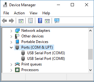
Linux
To find available serial devices on Linux:
- Find all serial ports
- Open a terminal and execute the following command:
dmesg | grep -E ttyU\?S↵ - The available ports should be listed similar to the following:
[ 2.029214] serial8250: ttyS0 at IO 0x3f8 (irq = 4) is a 16550A [ 2.432572] 00:07: ttyS0 at IO 0x3f8 (irq = 4) is a 16550A [ 2.468149] 0000:00:03.3: ttyS4 at IO 0xec98 (irq = 17) is a 16550A [ 13.514432] usb 7-2: FTDI USB Serial Device converter now attached to ttyUSB0
In this example, there are 3 serial ports available:ttyS0,ttyS4, andttyUSB0(a USB adaptor). - To determine which one corresponds to the USB serial cable connected to the Zaber device, try repeating the command with and without the cable connected to the computer, to see which one appears and disappears.
- Open a terminal and execute the following command:
- Check the port permissions
- Using the ports found in the example above, execute the following command:
ls -l /dev/tty{S0, S4, USB0}↵ - The permissions for each port should be listed similar to the following:
crw-rw---- 1 root dialout 4, 64 Oct 31 06:44 /dev/ttyS0 crw-rw---- 1 root dialout 4, 68 Oct 31 06:45 /dev/ttyS4 crw-rw---- 1 root dialout 188, 0 Oct 31 07:58 /dev/ttyUSB0
This shows that a user must berootor a member of thedialoutgroup to access the ports.
- Using the ports found in the example above, execute the following command:
- Check and update group permissions
- List the groups the current user is in with the following command:
groups↵ - The output will be similar to the following:
adm cdrom sudo dip plugdev users lpadmin sambashare
Notice thatdialoutis not in the list - If necessary, add the current user to the
dialoutgroup with the following command:sudo adduser $USER dialout↵Note: Group membership will not take effect until the next logon
- List the groups the current user is in with the following command:
macOS
To find available serial devices on macOS:
- Open a terminal and execute the following command:
ls /dev/cu.*serial*↵- The available ports should be listed similar to the following:
/dev/cu.usbserial-FTB3QAET /dev/cu.usbserial-FTEJJ1YW
In this example, there are 2 serial ports available, both of which happen to be USB adaptors. - There may be other devices that match this query, such as keyboards or some web cameras. To determine which one corresponds to the USB serial cable connected to the Zaber device, try repeating the command with and without the cable connected to the computer, to see which one appears and disappears.
- The available ports should be listed similar to the following: