LRT Gantry Series User's Manual
500 - 1500 mm XY travel; 75-500 mm Z travel; up to 100 kg load
Disclaimer
Zaber’s products are not intended for use in any critical medical, aviation, or military applications or situations where a product's use or failure could cause personal injury, death, or damage to property. Zaber disclaims any warranty of fitness for a particular purpose. The user of this product agrees to Zaber's general terms and conditions of sale.
Precautions
 Collision Hazard! Zaber Gantry products contain motion products with significant thrust and load capacities. Take caution to prevent collisions with operators, work surfaces, and sensitive equipment.
Heavy! Completely assembled gantry products, partial assemblies and some stage products can be very heavy. Exercise caution when lifting/moving larger assemblies and products. Loosely fasten risers and stage axes as soon as they are placed during assembly, to prevent tipping and falling hazards.
 Important: Gantry products must be properly assembled and aligned to function optimally. Follow assembly instructions closely and contact Zaber Customer Support for help at any time, if needed.
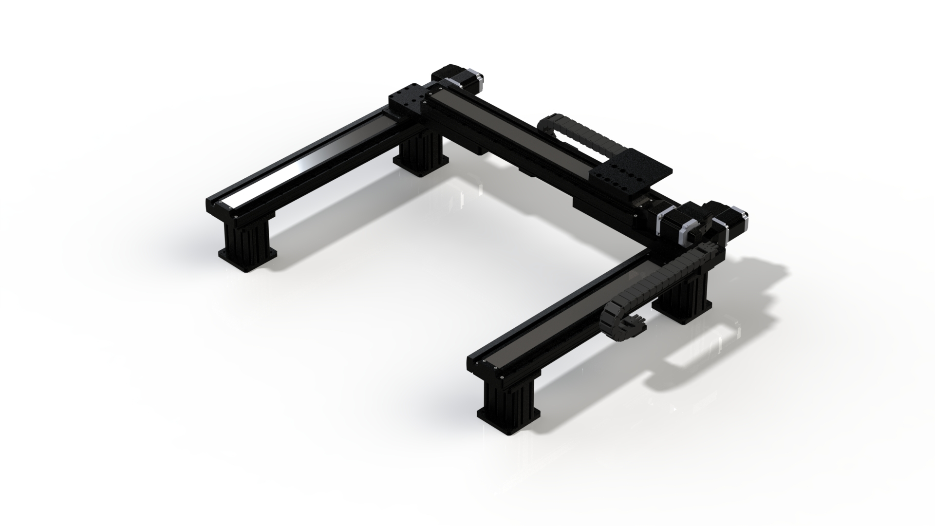
Product Overview
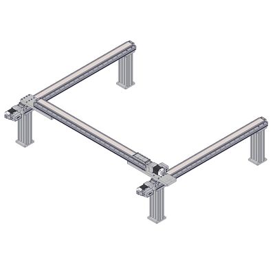
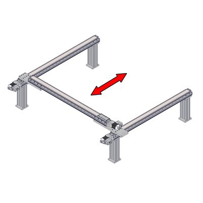
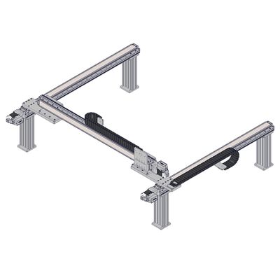
The following documentation uses specific terminology to refer to parts of the gantry product, outlined in the diagrams below:
| X-Axis Axes 1 and 2 |
Y-Axis | Z/Theta/End Effectors |
 |
 |

|
| X-Axis Cable Guide for Y-Axis cables and Optional Z/Theta/End Effector Cables |
Y-Axis Cable Guide for Z/Theta/End Effector cables |
 |

|
| X-Axis Stage Spacing Between Inner Fasteners | |
| Y-Axis Stage | Spacing in mm |
| LRT0500 | 800 |
| LRT0750 | 1050 |
| LRT1000 | 1300 |
| LRT1500 | 1800 |
LRT Family Configurations
All axes use CG02 cable guides by default. If your gantry has a Z-axis with a power-off brake, the X and Y axes will use CG06 cable guides instead. Devices with power-off brakes have a B in the options section of the part number (eg. LRT0500HL-BE08CT10A).
| Configuration (X-Axis by Y-Axis Travel) | Cable Guide Links for X-Axis Guide | Cable Guide Links for Y-Axis Guide | Recommended Minimum Breadboard Dimensions (mm x mm) | ||
| CG02 | CG06 | CG02 | CG06 | ||
| 500 x 500 | 23 | 28 | 22 | 32 | 625 x 975 |
| 500 x 750 | 23 | 28 | 28 | 36 | 625 x 1225 |
| 500 x 1000 | 23 | 28 | 34 | 40 | 625 x 1475 |
| 500 x 1500 | 23 | 28 | 47 | 48 | 625 x 1975 |
| 750 x 500 | 29 | 33 | 22 | 32 | 875 x 975 |
| 750 x 750 | 29 | 33 | 28 | 36 | 875 x 1225 |
| 750 x 1000 | 29 | 33 | 34 | 40 | 875 x 1475 |
| 750 x 1500 | 29 | 33 | 47 | 48 | 875 x 1975 |
| 1000 x 500 | 35 | 37 | 22 | 32 | 1125 x 975 |
| 1000 x 750 | 35 | 37 | 28 | 36 | 1125 x 1225 |
| 1000 x 1000 | 35 | 37 | 34 | 40 | 1125 x 1475 |
| 1000 x 1500 | 35 | 37 | 47 | 48 | 1125 x 1975 |
| 1500 x 500 | 48 | 45 | 22 | 32 | 1625 x 975 |
| 1500 x 750 | 48 | 45 | 28 | 36 | 1625 x 1225 |
| 1500 x 1000 | 48 | 45 | 34 | 40 | 1625 x 1475 |
| 1500 x 1500 | 48 | 45 | 47 | 48 | 1625 x 1975 |
| Z-Axis Travel | Cable Guide Links for Z-Axis Guide (CG02) |
| 100 | 17 |
| 250 | 24 |
| 500 | 25 |
Cables Lengths
Most stages use the MC10T3 series of cables. If your gantry has a Z-axis with a power-off brake, the Z-axis will use a MC10 series cable. Devices with power-off brakes have a B in the options section of the part number (eg. LRT0500HL-BE08CT10A).
Calculate the required cable length for each axis using the equations in the table below for the XY cable guides used on your gantry. Round these lengths up to the next available cable length shown in the cable part numbers table.
| Axis | Cable Length (mm) | |
| CG02 XY Cable Guides | CG06 XY Cable Guides | |
| X-Axis 1 | 1500 | 1500 |
| X-Axis 2 | XAxisTravel / 2 + YAxisTravel + 1000 | XAxisTravel / 2 + YAxisTravel + 1000 |
| Y-Axis | XAxisTravel / 2 + 900 | XAxisTravel / 2 + 1400 |
| Z-Axis | XAxisTravel / 2 + YAxisTravel + ZAxisTravel + 1400 | XAxisTravel / 2 + YAxisTravel + ZAxisTravel + 2400 |
| Cable Length (mm) | MC10T3 Series Cable Part Number | MC10 Series Cable Part Number |
| 600 | MC10T3L060 | MC10L060 |
| 1500 | MC10T3 | MC10 |
| 3000 | MC10T3L300 | MC10L300 |
| 4500 | MC10T3L450 | MC10L450 |
If a required cable length is longer than 4500mm, two 3000mm cables will be provided. They can be joined together between the X and Y axis cable guides. Do not locate the connectors within the cable guides.
Gantry Assembly and Setup
Zaber's gantry products require some assembly and set-up upon arrival. These gantries can be disassembled, packed, and transported for use in new locations, or re-configured with new motion control axes to suit new applications. To set up your gantry, complete the following steps (where applicable).
Note: Instructions are provided for all hardware variants used in different gantry configurations. Not all hardware will be used in your configuration. Section headings will contain applicable part numbers.
Contact Zaber Customer Support at any time for help or additional information.
Preparation
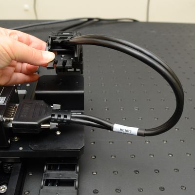
- Unpack the high-flex motor cables and hang them vertically by one end for 24 hours to relieve packaging stresses. If the cables are too long to be hung up in one piece, loosely coil them on a flat surface into a large diameter such as 60 cm (2 ft).
- Unpack the brackets, tools (provided with AP201 cross-members), cable guides and other hardware.
- Keep fasteners with their labelled bags to easily identify/locate the correct fastener for a step.
- Unpack the stage axes and identify the two identical X-axis stages, Y-axis stage and any additional axes you may have.
- Determine your mounting surface. The instructions provided assume a metric optical breadboard is used to mount the X-axis stages (or optional risers). See Product Overview for determining stage spacing and recommended breadboard dimensions.
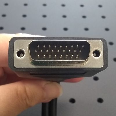
- Determine stage orientations and locations of cable guide(s) and controller. The controller is typically located on the end of the gantry near the motor cable connections on the peripheral devices. It's preferable to mount it closer to X-axis 1, as this axis will carry the cable tracking. If the controller is required to be mounted at a significant distance from the gantry, longer cables or cable extensions may be necessary. See MC10T3(Lxxx) for longer 15 pin female to 26 pin male cables or MC10(Lxxx) for 26 pin female to 26 pin male extensions cables here: Zaber Accessories.
- Note: 'xxx' denotes a length in cm
- Identify the cables intended for each axis using the matching configuration table in the Product Overview.
Tips
- Whenever allowable in your application, mount the CGxxT cable guide terminations to provide the largest bend radius for your cable.
X-MCC Setup and Stage Connection
Related Products
 |
 MC10T3L060 MC10T3L300 MC10T3L450 |
 |
Precautions
Important! Review the X-MCC User Manual for complete device precautions and operation instructions.
Important! Always remove power to the X-MCC controller before connecting or disconnecting peripherals.
Assembly
-
Determine which MC motor cables are required for each gantry peripheral. See the configuration table in Product Overview.
-
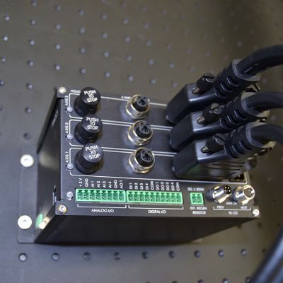
Connect the 26 pin male end of the MC cables to the X-MCC controller axes. Connect the cable for:
•X-axis 1 to X-MCC axis 1
•X-axis 2 to X-MCC axis 2
•Y-axis to X-MCC axis 3
•Optional Z/theta to X-MCC axis 4 (if present)
Tighten locking connector screws.
See Product Overview to identify the gantry axes. -
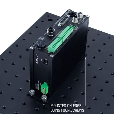
If desired, mount the X-MCC controller. See instructions in the X-MCC User Manual.
Note: Ensure the E-stop connector is reconnected with either the 'E-stop off' jumper or an E-stop (such as the ES01) to ensure controller function. -
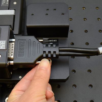
Connect the other end of each MC motor cable to the matching peripheral and tighten the locking connector screws.
Important: During gantry assembly you may wish to disconnect one or more peripherals. Always remove power to the X-MCC before connecting or disconnecting any peripheral. -

Connect the X-MCC controller to your computer using the USB cable (U-DC06) or to an X-JOY3 joystick with an X-DC cable (if a joystick is present).
Connect the X-MCC controller to one or more power supplies. -
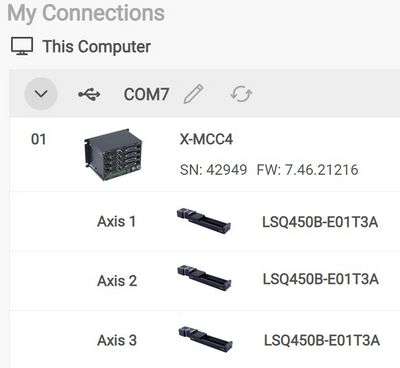
Open Zaber Launcher. Confirm that three stages are detected and activated. If a stage is not activated, an "Activate" button will appear next to it. See the X-MCC manual for more information on activating peripherals and setup.
LRT X-Axis Stages to Breadboard
Related Products
 |
Precautions
Heavy
Required Tools
- 5 mm hex key
Assembly
-
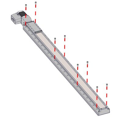
Mount the first X-axis stage to a breadboard or other mounting surface using the eight provided black M6 screws and a 5 mm hex key. Where possible, mount the stage using fasteners at each end of travel.
-
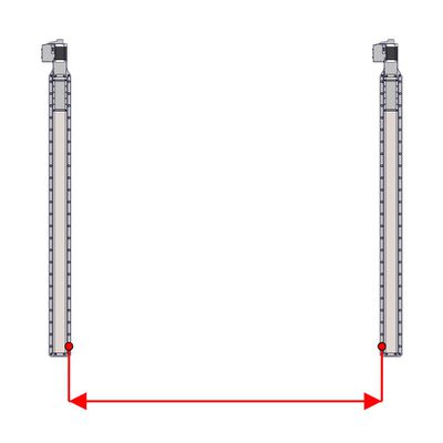
Locate the second stage at a distance from the first determined by the Y-axis travel (see chart in Product Overview) then repeat the previous step to mount the second stage.
To calculate the spacing for any length of Y-axis, use 300 mm + Y-axis travel. -
Firmly tighten all fasteners mounting the X-axis stages.
Using AP203 Risers
Related Products
 AP203H0300 Risers AP203H0500 Risers |
|
Precautions
Mounting/Tipping Hazard! The LRT-EC stages and AP203 risers can be heavy and may create a falling/tipping hazard during assembly. We recommend mounting the risers to a breadboard or other mounting surface before placing X-axis stages on top. Where possible, loosely install several screws between the stage and at least one riser to prevent accidental motion.
Important: Do not disassemble AP203 risers. They have been carefully aligned.
Required Tools
- 5 mm hex key
Assembly
-
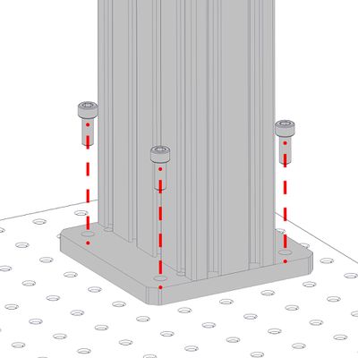
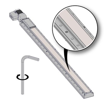
Loosely mount AP203 risers to a breadboard or other mounting surface using M6 x 16 screws (the shorter of the provided screws) and a 5 mm hex key. Install screws until snug, then back off a little to allow alignment.
Repeat until all screws are present. You may wish to leave the risers loose or just snug until complete assembly is done, then loosen and re-align as needed. -
See Product Overview for spacing between the indicated holes for your gantry configuration.
To calculate the spacing for any length of Y-axis, use 300 mm + Y-axis travel. -
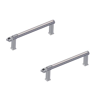
Space the additional riser(s) for a single stage as far apart as possible or approximately* equally spaced if using more than two per stage, along the travel of the X-axis stages.
*Note: If using an odd number of risers per stage, mount the mid-point riser slightly off of the centre of stage travel, to leave room for cable guide support mounting. -
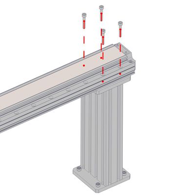
Mount stages to top of risers using the provided black M6 x 35 screws. Start by installing two screws diagonally for each riser, leaving screws just a bit loose. Snug them after all screws have been added.
Assembly of AP201 Crossmembers and Lockstep Setup
Related Products
 |
|
Precautions
Mounting Hazard! The LRT-EC Y-axis stage may be heavy and could create a falling hazard during assembly.
Important: If using AB209 brackets to mount the Y-axis of your system on its side, see Assembly of AP201 Crossmembers, AB209 Angle Brackets, and Lockstep Setup.
Required Tools
- 5 mm hex key
Assembly
-
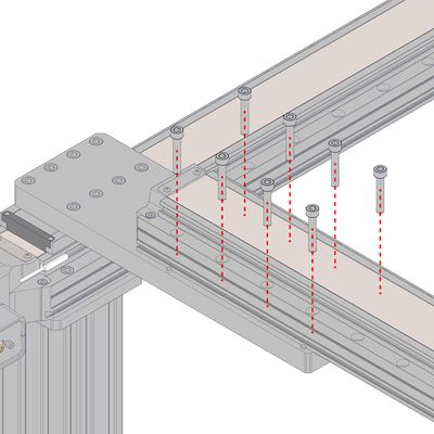
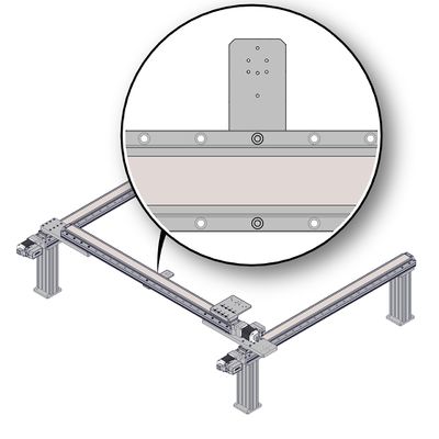
Loosely mount AP201 part 1 (longer of the two plates) on the X-axis 1 stage using a 5 mm hex key and eight of the provided M6 x 20 screws (the shorter of the two provided lengths).
Note: X-axis 1 is the stage closest to the controller and cable guide.
Note: The following steps show one orientation for the X- and Y-axis stages, but it is possible to assemble in other orientations. -
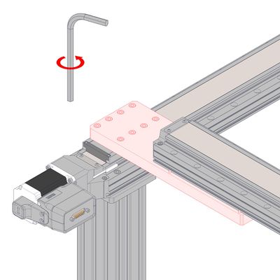
Push the AP201 part 1 as shown until the dowels on the bottom of the plate are both firmly in contact with the edge of the LRT carriage - this provides Y-axis alignment. While holding the AP201 in place, firmly tighten the M6 fasteners using the 5 mm hex key.
Note: Tightening in several steps, while alternating screws diagonally, may help prevent the plate from moving during this step. -
Loosely mount AP201 part 2 on the X-axis 2 stage using a 5 mm hex key and eight of the provided M6 x 20 screws.
Snug the plate down, but do not torque the screws. This plate will be loosened and aligned later. -
See X-MCC Setup and Stage Connection if you have not already connected your stages.
Open Zaber Launcher. Confirm that three stages are detected and activated. -
Using Zaber Launcher, send a home command to each of the two X-axis stages to move them to their home positions.
-
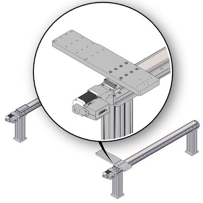
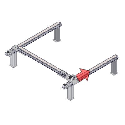
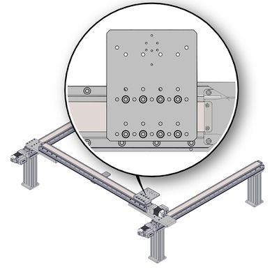
Place the Y-axis stage on top of the two AP201 plates with the connector end closest to the X-axis 1 stage, on the longer of the two plates.
-
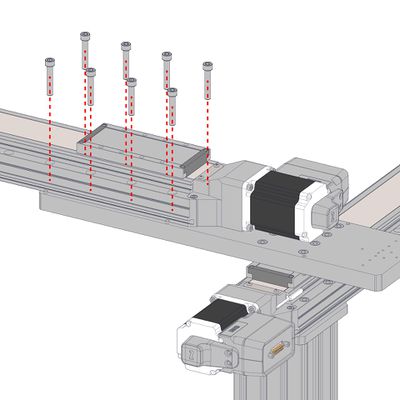
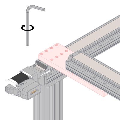
Using eight of the M6 x 35 screws with the AP201, loosely assemble the Y-axis stage to the AP201 part 1 (the longer plate).
-

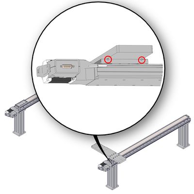
With screws still loose, push the Y-axis stage firmly against the two dowels on the AP201 part 1 (the longer plate). With both dowels in contact, firmly tighten the M6 screws between the AP201 part 1 (larger plate) and the Y-axis stage.
Important: Do not loosen these screws again - they provide the alignment between X- and Y-axes. -
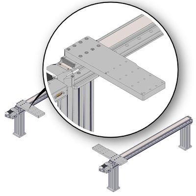
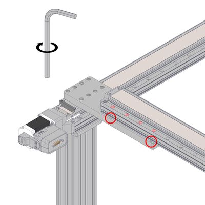
Loosely add screws between the Y-axis stage and the AP201 part 2 (the shorter plate).
-
If the screws do not align with the threaded holes, loosen the AP201 part 2 plate from the X-axis stage. Support the Y-axis and move the AP201 plate around until the Y-axis stage screws can start to thread in.
-
If the plates are not well aligned (the Y-axis stage can not sit flat against all dowels at the same time), move one X-axis stage forward in steps by sending small move rel commands (100 um to 500um is recommended).
-
Thread in several screws loosely between the Y-axis stage at the AP201 plate, then firmly re-tighten the screws between the AP201 part 2 and the X-axis 2 stage.
-
Do not tighten the Y-axis stage screws unless the stage rests on all 4 AP201 dowels simultaneously.
When the Y-axis stage aligns well with all dowels, firmly tighten the fasteners between the Y-axis stage and the AP201 part 2. -
In Zaber Launcher, use the Lockstep Configuration App to lock the motion of the two X-axis stages together.
-
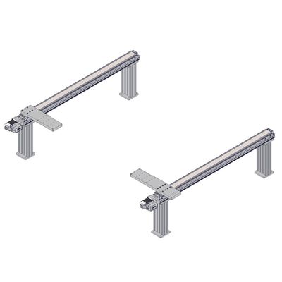
Home the lockstep group in Zaber Launcher, then move the X-axis stages throughout their travel ranges slowly using the manual control knob for axis 1 or 2. If the stages move well, move them at higher speeds using the Zaber software or the manual control knobs.
See Troubleshooting if stages are not moving well together.
Installing AP207 Cable Guide Mounts for Y- or Z-Axis Cable Guides
Related Products
 |
|
Required Tools
- 5 mm hex key
Assembly
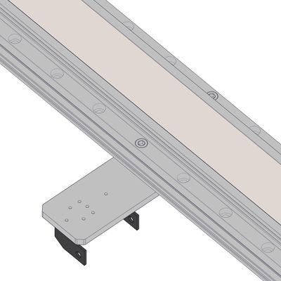
-
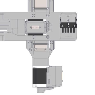
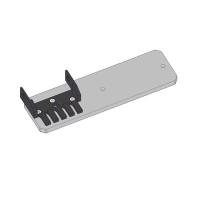
Mount the AP207 part 1 to the LRT X-axis 1 stage in mid-travel, using the provided M6 x 30 screws and a 5 mm hex key.
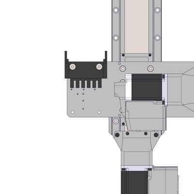
-
Install AP207 part 2 onto the top of the Y axis LRT stage using four M6 x 20 mm screws and the 5 mm hex key. Align the stage top and AP207 part 2 edges to each other. Alternate tightening fasteners in a diagonal pattern to snug, then tightly secure.
Z-Axis Installation
Related Products
|
|
|
Precautions
Important: Where possible, mount all Z/theta/end effector axes as close to the Y-axis stage as possible to reduce moment loading and off-axis motion errors.
Required Tools
- 5 mm hex key
Assembly
-
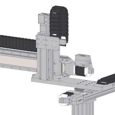
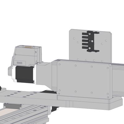
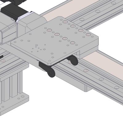
Additional axes can be mounted directly to the top of the AP207 part 2 as shown.
-
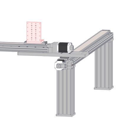
For additional axes at 90 degrees to the AP207 part 2, add an angle bracket such as the AB210. Use the provided M6 mounting screws and a 5 mm hex key to attach the bracket.
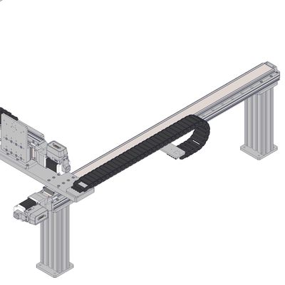
-
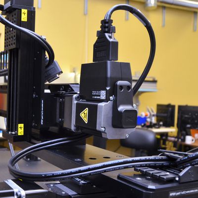
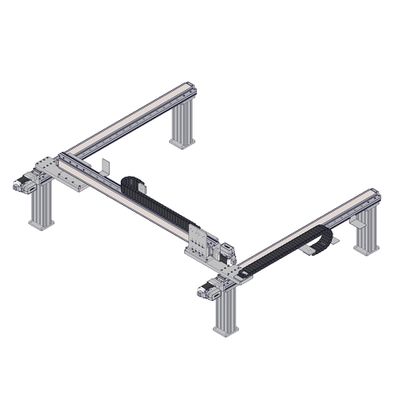
An LRT Z-axis stage and cable guide assembly mounted with an AB210 bracket is shown here.
CG Cable Guide and Cable Assembly
Related Products
 |
 |
 |
 |
 |
 |
MC10T3L060 MC10T3L300 MC10T3L450 |
|
Precautions
Important: Ensure cables are not twisted along their length. This can reduce cable lifetime.
Assembly
-
Ensure all motor cables are connected to the correct peripherals before building the cable guides.
-
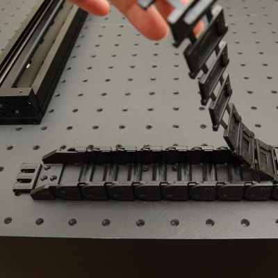
Determine the number of links required for the X-axis guide and, if present, the Y-axis guide. See the Product Overview for configuration specific quantities.
Peel open the cable guide. -
Break the CGxx chain at the appropriate position.
-
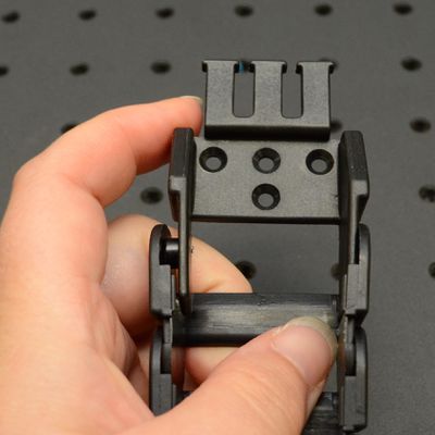
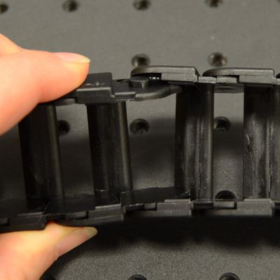
Attach the CGxxT parts to the mating ends of the CGxx.
Note: You may need to remove these temporarily to attach them to the mounting adaptors. -
Lay out the cable guide and determine which way it will bend and where the CGxxT terminations will mount to the cable guide adaptors.
Note: If using CG06T, the pivoting termination should mount to the upper cable guide adapter. -
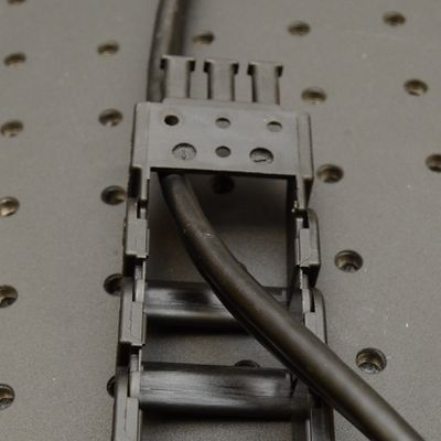
Lay cables in the guides, ensuring that the peripheral connectors are exiting the top end of the guide. Remove any twists in the cable(s) and lay them in the centre of the guide. Minimize twists outside the cable guide.
Important: If you are using a Y-axis cable guide, ensure that the cable(s) for the Z/theta axis and any end effectors are also included in the X-axis cable guide. -
Close the CGxx cable guide by clicking the parts together.
Note: The CGxx cable guide parts must be oriented as shown to click together. -
Ensure 150-200 mm (6-8 inches) of cable length extends from the top end of the cable guide where it will connect.
-
Terminations can be attached in two orientations, depending on how they will attach to the mounting adaptors. If the termination needs to be flipped, you will need to assemble the cable in the guide then remove and re-attach the termination as shown.
Installing AP205 Cable Guide Mounts for X-Axis Cable Guides
Related Products
 |
|
|
|
|
Precautions
Important: Creating a loop in the cable of 150-200 mm (6-8 inches) between the top cable guide mount and the Y-axis stage protects the cable and increases cycle lifetime.
Required Tools
- 5 mm hex key
- 2 mm hex key
Assembly (CG01 or CG02)
-
Attach the upper termination of the cable guide to the AP201 part 1 using M3 flathead screws and the 2 mm hex key.
-
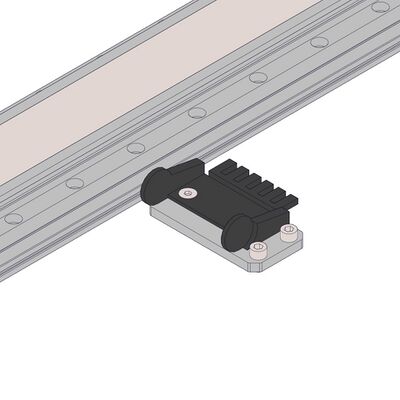
Attach the lower termination of the cable guide to AP205.
-
Mount the AP205 to the LRT X-axis 1 stage in mid-travel, using the provided M6 x 30 screws and a 5 mm hex key.
-
Confirm that the cable guide is in the desired orientation.
Assembly (CG06)
-

Identify the pivoting termination of CG06T. This is the termination with the holes for connecting the cable guide links.
-
Attach the upper pivoting termination of the cable guide to the AP201 part 1 using two M6 flathead screws and the 4 mm hex key.
-
Attach the lower termination of the cable guide to AP205.
-
Mount the AP205 to the LRT X-axis 1 stage in mid-travel, using the provided M6 x 30 screws and a 5 mm hex key.
-
Confirm that the cable guide is in the desired orientation.
Installing AP206 Cable Guide Mounts for X-Axis Cable Guides
Related Products
 |
|
|
|
Precautions
Important: Creating a loop in the cable of 150-200 mm (6-8 inches) between the top cable guide mount and the Y-axis stage protects the cable and increases cycle lifetime.
Required Tools
- 5 mm hex key
- 2 mm hex key
Assembly
-
Attach the upper termination of the cable guide to the AP201 part 1 using M3 flathead screws and the 2 mm hex key.
-
Hold the cable guide up as it will be installed to determine how the adaptors should be oriented.
-
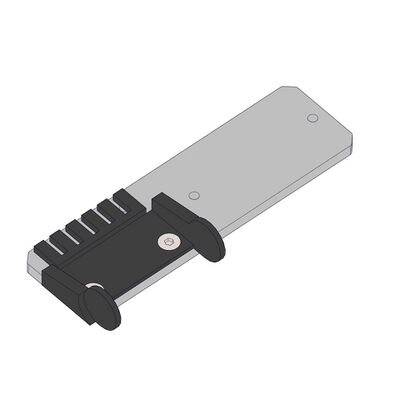
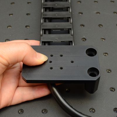
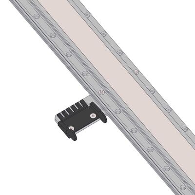
Attach the AP206 to the lower termination of the cable guide (CG01T shown here).
Mount the AP206 to the breadboard near the mid-point of X-axis travel, using the provided M6 screws and a 5 mm hex key.
Installing AP268 Cable Guide Mounts for CG06 X-Axis Cable Guides
Related Products
 |
|
|
Precautions
Important: Creating a loop in the cable of 150-200 mm (6-8 inches) between the top cable guide mount and the Y-axis stage protects the cable and increases cycle lifetime.
Required Tools
- 5 mm hex key
- 4 mm hex key
Assembly
-
Identify the pivoting termination of CG06T. This is the termination with the holes for connecting the cable guide links.
-
Attach the upper pivoting termination of the cable guide to the AP201 part 1 using two M6 flathead screws and the 4 mm hex key.
-
Attach the lower termination of the cable guide to AP268.
Mount the AP268 to the breadboard near the mid-point of X-axis travel, using the provided M6 screws and a 5 mm hex key. -
Confirm that the cable guide is in the desired orientation.
Installing CG Cable Guides with AP207
Related Products
|
|
|
|
|
Precautions
Important: Creating a loop in the cable of 150-200 mm (6-8 inches) between the top cable guide mount and the Y-axis stage protects the cable and increases cycle lifetime.
Assembly (CG01 or CG02)
-
Ensure cables for Y-axis, additional axes, and end effectors have a 150-200 mm (6-8 inches) loop as they exit the X-axis cable guide.
-
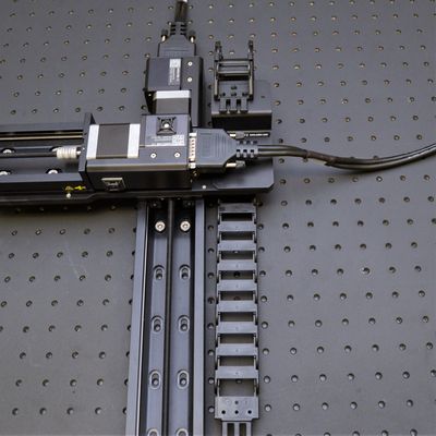
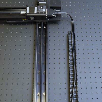
Connect upper cable guide termination to AP207 part 2 as shown.
-
Connect the cable guide to the bottom side of AP207 part 1 as shown.
-
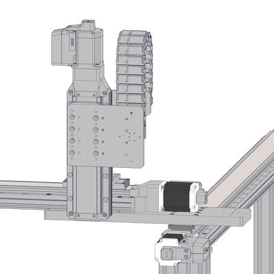
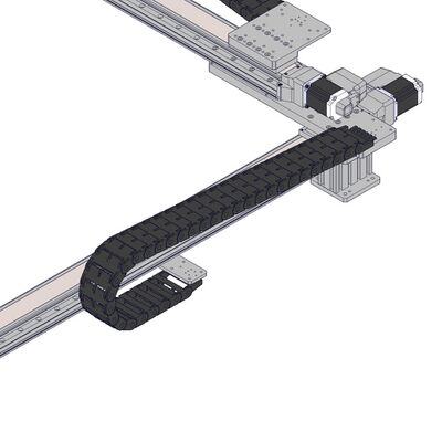
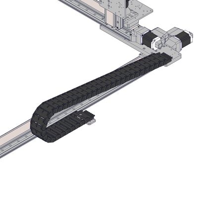
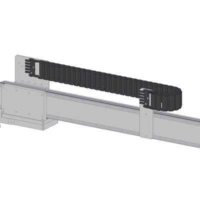
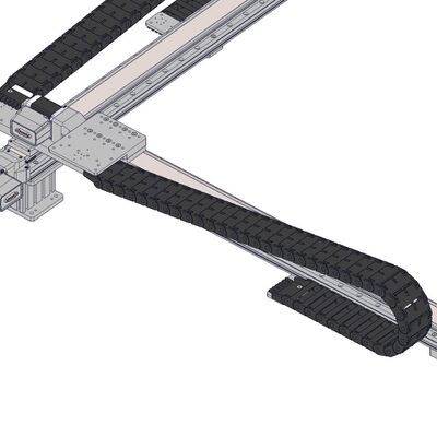
The Y-axis of a LRT gantry is shown here with the cable guide installed.
Assembly (CG06)
-
Ensure cables for Y-axis, additional axes, and end effectors have a 150-200 mm (6-8 inches) loop as they exit the X-axis cable guide.
-
Identify the pivoting termination of CG06T. This is the termination with the holes for connecting the cable guide links.
-
Attach the upper pivoting termination of CG06T to AP207 part 2 as shown using M6 flathead screws.
-
Attach the lower termination of the cable guide to the top of AP207 part 1 as shown.
-
Confirm that the cable guide is in the orientation shown.
Installing AP211 Cable Guide Supports
Related Products
 |
|
Precautions
Important: AP211 cable guide supports are not compatible with CG06 cable guides. Supports are not required for CG06.
Required Tools
- 2 mm hex key
Assembly
-
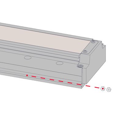
Insert the two M3 nuts into the slot on the side of the LRT Y-axis stage where the cable guide will be mounted.
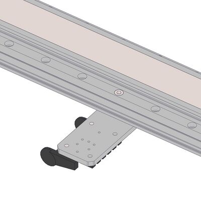
Note: Cable guide mounting location may vary depending on your configuration. The configuration shown here may not match your assembly. -
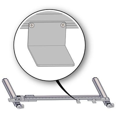
Loosely attach two M3 flathead screws through the AP211 to the nuts in the LRT stage slot.
Slide the AP211 along the Y-axis stage to the desired location before tightening the fasteners.
Place a single adaptor at approximately 3/4 of the travel of the Y-axis stage (away from the motor).
For two adaptors, space them equally between 2/3 of the travel and the end of travel of the Y-axis stage. -
Install AP211 adaptors for additional axes as needed, including support for X-axis cable guides when risers are used.
Cable Management
Related Products
|
|
MC10T3L060 MC10T3L300 MC10T3L450 |
Precautions
Important: Creating a loop in the cable of 150 to 200 mm (6-8 inches), between the top cable guide mount and the Y-axis stage, protects the cable and increases cycle lifetime.
Required Tools
- cable ties
- cable tie mounts
- scissors
Assembly
-
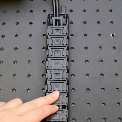
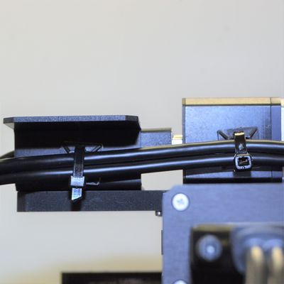
Use cable ties (provided in CGxxT kit) to loosely secure cables to the prongs on the CGxxT as shown, to restrict their motion.
-
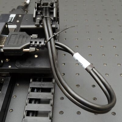
Create the loop of cable using at least 150 to 200 mm (6-8 inches) of cable, for each cable as it exits the guide.
-
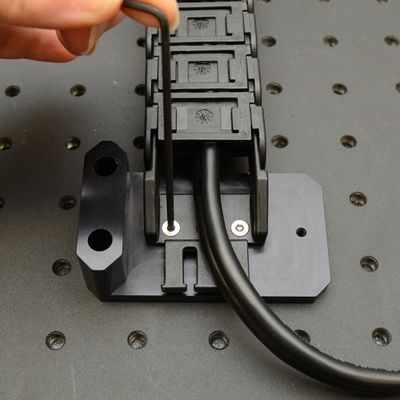
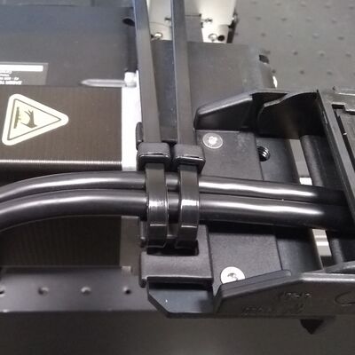
For cables to Z/theta and end effector devices, route the cable(s) beside the Y-axis stage and use an adhesive-backed cable tie mount (provided in the CGxxT kit) and a cable tie to hold the cable in place as shown.
-
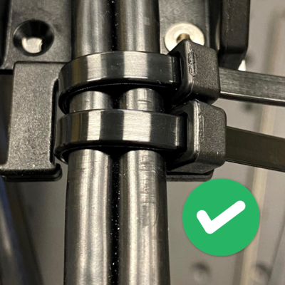
To create the upper strain relief tighten two cable ties on the upper prongs of the CGxxT and the cable. The cable ties should be loose enough that you can move the cable though them fairly easily by hand, but tight enough to constrain the external cable jacket. This allows the internal cable wires to move through the strain relief to relieve bending stresses during motion.
-
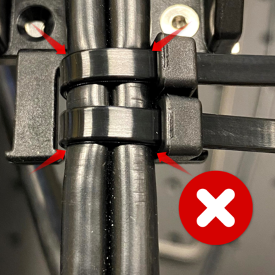
The cable ties in this image have been overtightened and are pinching the cable jacket. Remove ties and start again if needed.
-
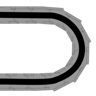
Adjust the cable position inside the guide.
1. The cable should be in the centre of the guide, not pulled tight against the inner radius or pushed against the outer radius of the bend.
2. Holding the cable gently on the controller side of the cable, move the stage along its entire range of travel several times and ensure the cable runs freely in the guide. -
Tighten the cable tie on the second CGxxT prongs to create the lower strain relief, matching the snugness of the first termination.
Trim the ends of the cable ties.
Disassembly
To disassemble, follow the assembly procedures in reverse. Please keep the following guidelines in mind:
- Remove power before attempting to disassemble devices to prevent unexpected motion
- Retain fasteners for future use
- Keep cable guide assemblies intact
Operation
Setting Lockstep Tolerance
The lockstep tolerance limits the amount of twist between the two lockstepped stages as they travel. If the tolerance is exceeded, the devices will be brought to a stop, to prevent device damage from excessive twist. We recommend adjusting the default setting to larger values (up to the maximum safe values presented below for your specific configuration). Setting a larger tolerance reduces the risk of unexpected or jarring stops and should not affect the typical operating performance of the lockstepped stages.
| X-Axis Part Number | Y-Axis Part Number1 | Maximum Lockstep Tolerance Setting (microsteps)2 |
| LRTxxxxAx | LRT0500xx | 9472 |
| LRT0750xx | 12178 | |
| LRT1000xx | 14884 | |
| LRT1500xx | 20297 | |
| LRTxxxxBx | LRT0500xx | 2368 |
| LRT0750xx | 3045 | |
| LRT1000xx | 3721 | |
| LRT1500xx | 5074 | |
| LRTxxxxDx | LRT0500xx | 592 |
| LRT0750xx | 761 | |
| LRT1000xx | 930 | |
| LRT1500xx | 1269 | |
| LRTxxxxHx | LRT0500xx | 3007 |
| LRT0750xx | 3867 | |
| LRT1000xx | 4726 | |
| LRT1500xx | 6444 |
- 1 Assumes standard mounting using AP201 hardware to determine spacing between X-axis stages.
- 2 Allows misalignment to a maximum of 0.10 degrees.
Device Product Manuals
Zaber's gantry products include combinations of several Zaber motion control devices. For device operation, maintenance procedures and troubleshooting, consult the detailed product manuals for these devices:
- X-MCC Universal Drive Controller
- These controllers are available with 1-4 axes. In a gantry, a three or four axis controller is typically used to operate the two X-axis stages in lockstep, and to provide coordinated motion for up to two additional axes of motion. This controller may be daisy-chained with other Zaber controllers or motion devices with integrated control.
- LSQ-E Linear Stage
- Provides X,Y and optional Z axis linear motion in LSQ-E Gantries.
- LSQ-EC Linear Stage
- Provides X,Y and optional Z axis linear motion in LSQ-EC Gantries.
- LRT-EC Linear Stage
- Provides X,Y and optional Z axis linear motion in LRT-EC Gantries.
- LC40B-KM01 Linear Guide with Integrated Controller Motor Kit
- Provides X,Y linear motion in LC40 Gantries.
- LC40B-KM02 Linear Guide with Motor Kit for External Controller
- Provides X,Y linear motion in LC40 Gantries.
- LC40C-KM03 Linear Cantilever Axis with Integrated Controller Motor Kit
- Provides X,Y linear motion in LC40 Gantries.
- LC40C-KM04 Linear Cantilever Axis with Motor Kit for External Controller
- Provides X,Y linear motion in LC40 Gantries.
- RSW Rotary Stage
- Provides and optional rotary axis to a gantry.
Additional Zaber motion products can be used in any Zaber gantry. Product Manuals can be found through their product pages here: Zaber Products
Troubleshooting a Gantry product
The following sections contain tips for troubleshooting gantry behavior. Please also see the Device Product Manuals for individual stage behavior, indicator information, and additional troubleshooting.
Unexpected Behaviour
- An axis doesn't respond to a move command.
- The axis stage(s) may need to be homed before use. Send the home command, or the lockstep home command if the axis is in a lockstep group (X-axis).
- Ensure commands addressed to lockstep group stages (X-axis) are lockstep motion commands.
- A peripheral won’t move and move commands are rejected.
- The peripheral may have been unplugged and plugged back in to the wrong axis. Send the activate command the peripheral to continue using it.
- The device is moving on its own and running against the ends of travel.
- The position encoder has de-synchronized.
- Reset the device by power cycling it or sending the system reset (T:0) command, then re-initialize it with the home (T:1) command.
- The X-axis stages have stopped unexpectedly during a move.
- See warning flags for more information.
- A stage may have stalled. See X-MCC Troubleshooting.
- Lockstep twist tolerance may have been exceeded. Consider adjusting lockstep tolerance. See Operation section for maximum recommended settings.
- Lockstepped Stages Stuck or Not Moving Well
- Alignment may not be ideal or stages may have become twisted.
- Disable the lockstep group by sending lockstep setup disable. Typically this will look like 'lockstep 1 setup disable'.
- Perform alignment steps, homing, and lockstep setup again.
Warranty and Repair
For Zaber's policies on warranty and repair, please refer to the Ordering Policies.
Standard products
Standard products are any part numbers that do not contain the suffix ENG followed by a 4 digit number. Most, but not all, standard products are listed for sale on our website. All standard Zaber products are backed by a one-month satisfaction guarantee. If you are not satisfied with your purchase, we will refund your payment minus any shipping charges. Goods must be in brand new saleable condition with no marks. Zaber products are guaranteed for one year. During this period Zaber will repair any products with faults due to manufacturing defects, free of charge.
Custom products
Custom products are any part numbers containing the suffix ENG followed by a 4 digit number. Each of these products has been designed for a custom application for a particular customer. Custom products are guaranteed for one year, unless explicitly stated otherwise. During this period Zaber will repair any products with faults due to manufacturing defects, free of charge.
How to return products
Customers with devices in need of return or repair should contact Zaber to obtain an RMA form which must be filled out and sent back to us to receive an RMA number. The RMA form contains instructions for packing and returning the device. The specified RMA number must be included on the shipment to ensure timely processing.
Email Updates
If you would like to receive our periodic email newsletter including product updates and promotions.
Contact Information
Contact Zaber Technologies Inc by any of the following methods:
| Phone | 1-604-569-3780 (direct) 1-888-276-8033 (toll free in North America) |
|---|---|
| Fax | 1-604-648-8033 |
| #2 - 605 West Kent Ave. N., Vancouver, British Columbia, Canada, V6P 6T7 | |
| Web | www.zaber.com |
| Please visit our website for up to date email contact information. |
The original instructions for this product are available at https://www.zaber.com/manuals/LRT-GANTRY.
Appendix A: Default Settings
Please see the Zaber Support Page for default settings for this device.
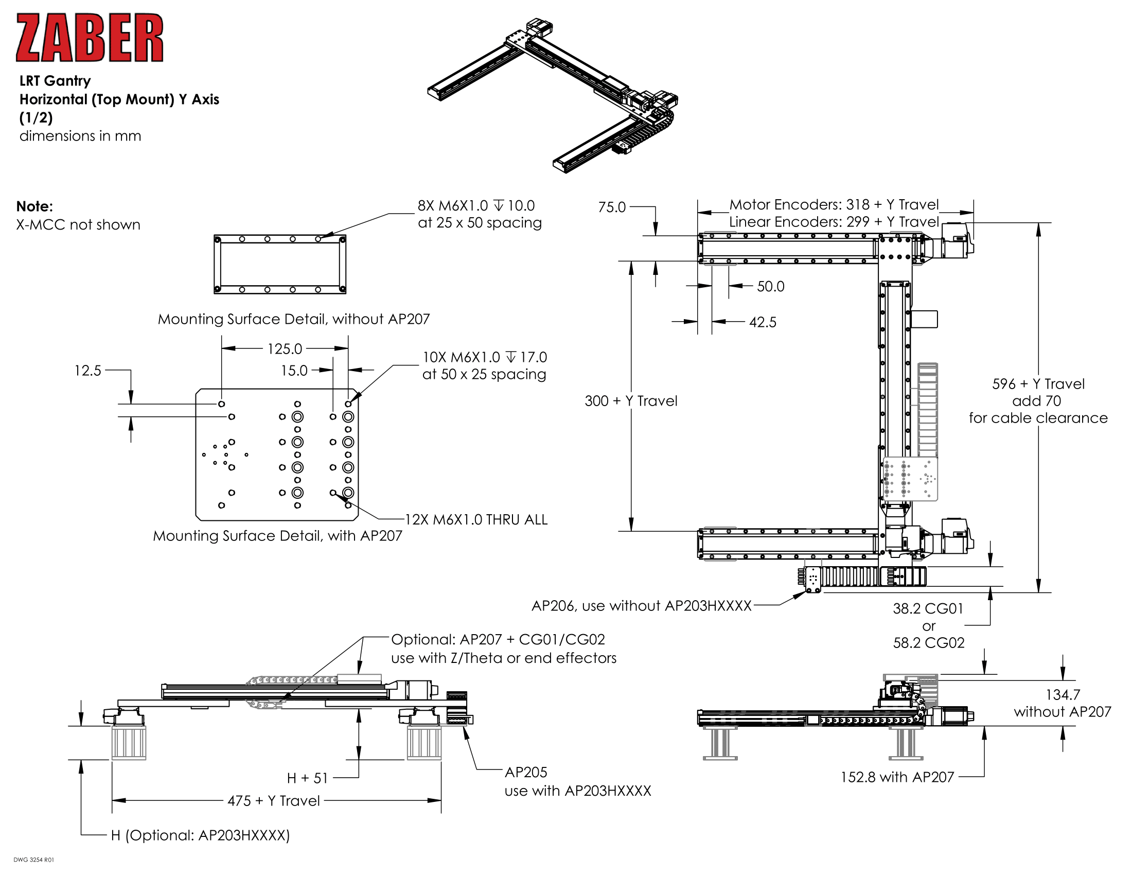
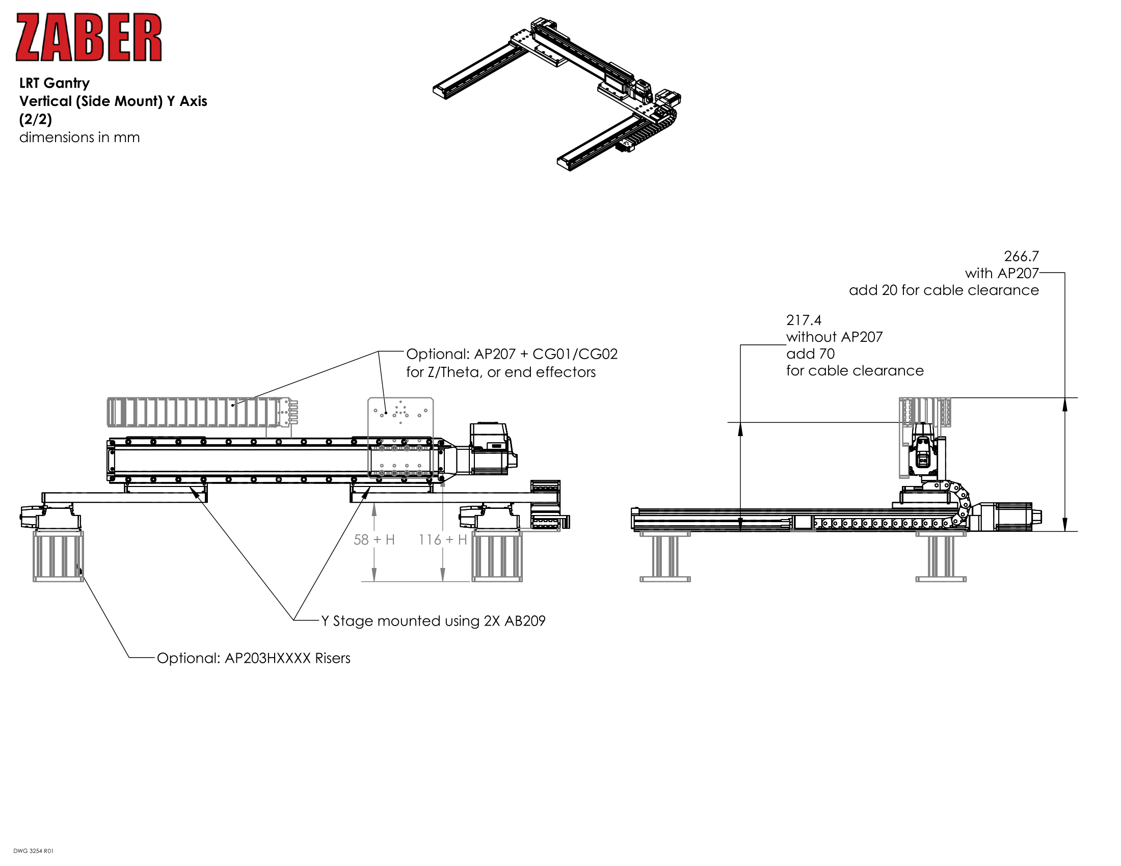
Product Drawings
Specifications
| Specification | Value | Alternate Unit |
|---|---|---|
| X Travel Range | 500 – 1500 mm | |
| Y Travel Range | 500 – 1500 mm | |
| Z Travel Range | 75 – 500 mm | |
| Load Capacity | 100 kg | |
| Repeatability | < 6-12 µm | |
| Maximum Speed | 700 mm/s | 27.559"/s |
| Maximum Continuous Thrust | 1200 N | 269.1 lb |
| CE Compliant | Yes |
Charts and Notes
| LSQ GANTRY | |||
|---|---|---|---|
| Y axis Travel | Maximum Y axis Deflection / Load 1 | ||
| 150 mm | 1.4 µm/kg | ||
| 300 mm | 5.3 µm/kg | ||
| 450 mm | 10.8 µm/kg | ||
| 600 mm | 20.1 µm/kg | ||
1: for an LSQ gantry assembled using AP200 crossmembers
| LSQ GANTRY - Combined Two Axis Repeatability | |||
|---|---|---|---|
| Y-Axis X-Axis | LSQxxxA | LSQxxxB | LSQxxxD |
| LSQxxxA | < 3 µm | < 4 µm | < 11 µm |
| LSQxxxB | < 4 µm | < 5 µm | < 11 µm |
| LSQxxxD | < 11 µm | < 11 µm | < 15 µm |
| LRT GANTRY | |||
|---|---|---|---|
| Y axis Travel | Maximum Y axis Deflection / Load 1 | ||
| 500 mm | 3.5 µm/kg | ||
| 750 mm | 12 µm/kg | ||
| 1000 mm | 20 µm/kg | ||
| 1500 mm | 40 µm/kg | ||
1: for an LRT gantry assembled using AP201 crossmembers
| LRT GANTRY - Combined Two Axis Repeatability | ||||
|---|---|---|---|---|
| Y-Axis X-Axis | LRTxxxA | LRTxxxB | LRTxxxD | LRTxxxH |
| LRTxxxA | < 6 µm | < 6 µm | < 9 µm | < 6 µm |
| LRTxxxB | < 6 µm | < 6 µm | < 9 µm | < 6 µm |
| LRTxxxD | < 9 µm | < 9 µm | < 12 µm | < 9 µm |
| LRTxxxH | < 6 µm | < 6 µm | < 9 µm | < 6 µm |
| LC40 GANTRY - Recommended Support | |||
|---|---|---|---|
| Load | Maximum Span Between Supports | ||
| 0 kg | 1.4 m | ||
| 1 kg | 1.3 m | ||
| 2 kg | 1.1 m | ||
| 5 kg | 0.9 m | ||
| 10 kg | 0.8 m | ||
| 20 kg | 0.6 m | ||
| 50 kg | 0.5 m | ||
For detailed specs for the specific stages used in the GANTRY, visit the following page:
This product uses the FreeRTOS kernel. FreeRTOS is © 2026 Amazon.com, Inc. or its affiliates and is governed by the following license:
All rights reserved.
Permission is hereby granted, free of charge, to any person obtaining a copy of this software and associated documentation files (the "Software"), to deal in the Software without restriction, including without limitation the rights to use, copy, modify, merge, publish, distribute, sublicense, and/or sell copies of the Software, and to permit persons to whom the Software is furnished to do so, subject to the following conditions:
The above copyright notice and this permission notice shall be included in all copies or substantial portions of the Software.
THE SOFTWARE IS PROVIDED "AS IS", WITHOUT WARRANTY OF ANY KIND, EXPRESS OR IMPLIED, INCLUDING BUT NOT LIMITED TO THE WARRANTIES OF MERCHANTABILITY, FITNESS FOR A PARTICULAR PURPOSE AND NONINFRINGEMENT.
IN NO EVENT SHALL THE AUTHORS OR COPYRIGHT HOLDERS BE LIABLE FOR ANY CLAIM, DAMAGES OR OTHER LIABILITY, WHETHER IN AN ACTION OF CONTRACT, TORT OR OTHERWISE, ARISING FROM, OUT OF OR IN CONNECTION WITH THE SOFTWARE OR THE USE OR OTHER DEALINGS IN THE SOFTWARE.
This product uses the LZ4 compression library. LZ4 is © 2011–2016 Yann Collet and is governed by the following license:
All rights reserved.
Redistribution and use in source and binary forms, with or without modification, are permitted provided that the following conditions are met:
- Redistributions of source code must retain the above copyright notice, this list of conditions and the following disclaimer.
- Redistributions in binary form must reproduce the above copyright notice, this list of conditions and the following disclaimer in the documentation and/or other materials provided with the distribution.
THIS SOFTWARE IS PROVIDED BY THE COPYRIGHT HOLDERS AND CONTRIBUTORS "AS IS" AND ANY EXPRESS OR IMPLIED WARRANTIES, INCLUDING, BUT NOT LIMITED TO, THE IMPLIED WARRANTIES OF MERCHANTABILITY AND FITNESS FOR A PARTICULAR PURPOSE ARE DISCLAIMED. IN NO EVENT SHALL THE COPYRIGHT HOLDER OR CONTRIBUTORS BE LIABLE FOR ANY DIRECT, INDIRECT, INCIDENTAL, SPECIAL, EXEMPLARY, OR CONSEQUENTIAL DAMAGES (INCLUDING, BUT NOT LIMITED TO, PROCUREMENT OF SUBSTITUTE GOODS OR SERVICES; LOSS OF USE, DATA, OR PROFITS; OR BUSINESS INTERRUPTION) HOWEVER CAUSED AND ON ANY THEORY OF LIABILITY, WHETHER IN CONTRACT, STRICT LIABILITY, OR TORT (INCLUDING NEGLIGENCE OR OTHERWISE) ARISING IN ANY WAY OUT OF THE USE OF THIS SOFTWARE, EVEN IF ADVISED OF THE POSSIBILITY OF SUCH DAMAGE.