X-MCC Series User's Manual
Multi-axis universal motor controllers
Disclaimer
Zaber’s products are not intended for use in any critical medical, aviation, or military applications or situations where a product's use or failure could cause personal injury, death, or damage to property. Zaber disclaims any warranty of fitness for a particular purpose. The user of this product agrees to Zaber's general terms and conditions of sale.
Precautions
The X-MCC controller is intended to drive a wide variety of Zaber peripheral axes. Damage to the peripheral may result if the settings are not correct. Always follow the instructions in Activating Peripherals when switching between peripherals.
 WARNING: Serious damage can occur to peripheral axes when operated with significantly higher-than-rated current. The X-MCC controller can provide up to 6 A of current to a peripheral. BEFORE CONNECTING A NEW PERIPHERAL to the X-MCC controller, it is important to set the correct parameters in the controller or ensure you are using an autodetect peripheral (Zaber product with a part number ending in 'A'). Please check the rated current for any peripheral axis before changing the current settings on the X-MCC from the default values. If you have any questions, please contact Zaber Technical Support.
WARNING: Instant stopping of a moving axis through the axis knob or E-Stop may result in damage to the peripheral product and reduced lifespan. Use sparingly if the axis is under heavy load.
 Important: Align connectors carefully to prevent pin damage.
Conventions used throughout this document
- Fixed width type indicates communication to and from a device. The
 symbol indicates a carriage return, which can be achieved by pressing enter when using a terminal program.
 - When referring to commands that involve physical distances, this manual uses the term 'increments'. For stepper motor products, this term refers to the microstep size of the positioner. For non-stepper devices, the term refers to the size of an encoder count. See the command protocol for more details.
Quick Tutorial
We recommend using Zaber Launcher to communicate with the device(s). For other software options, see the Software page. Please refer to the Protocol Manual for more detailed information on the available commands.
Initial Set-up
- Connect peripheral(s) to the desired axes of your X-MCC, while unpowered.
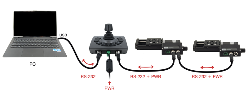
- Daisy chain all integrated devices and controllers together using the RS-232 "Prev" and "Next" connectors (see Daisy-Chaining Devices for more details).
- Next, supply power to one or more devices. Many products share power through the daisy-chain cables. The green power indicator on each should light up.
- Download and install Zaber Launcher. Start Zaber Launcher.
- Create a New Connection and select the communications port the first controller is connected to. For instructions on how to find the available communication ports on your system, please refer to: Appendix A - Available Communications Ports.
- If multiple devices are detected and there are conflicting device numbers, Zaber Launcher will renumber them or you can renumber them as desired. The first device in the chain (closest to the computer) will become Device 1, the next will become Device 2, and so on.
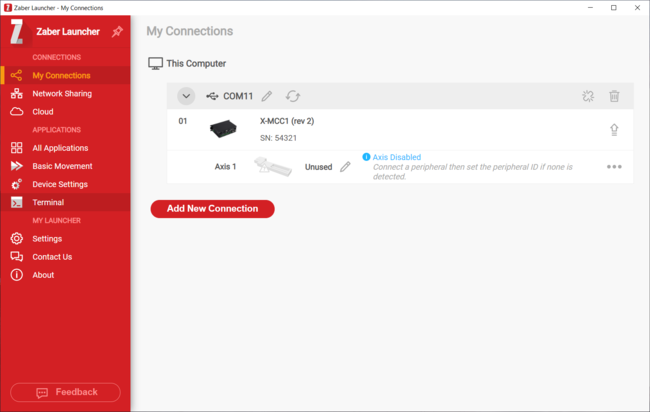
- When the communication port is open, Zaber Launcher's "My Connections" page will indicate the connection status of each axis with a message suggesting what action may be needed. See the Activating Peripherals section for additional information.
- Once a peripheral has been activated, either press the Home icon in Zaber Launcher's "Basic Movement" app or turn a knob on the X-MCC to move the peripheral associated with that axis. Most Zaber positioners will only move at reduced speed in one direction until they reach a home sensor at one limit of travel. Then they will move in both directions over full travel.
Initialization
Always connect peripherals to the controller when the controller is not powered. Peripherals should not be connected or disconnected while the controller is powered on.
Every time the controller is powered up or reset, you should return the motorized peripheral(s) to the home position. This is achieved by sending the home command to the individual device or all devices. Until this is done, most positioners will only allow motion in one direction, towards the sensor.
On stepper motor peripherals, a park command can be used to allow the device to be turned off and then used at a later time without the need to home the axis. See the tools parking command for details.
Using the Device
Several commonly used ASCII commands are shown below. For a full list of available commands, please refer to the Protocol Manual.
| Command | Description |
|---|---|
| /1 1 get pos
|
Query the current position of Device #1 Axis #1. |
| /1 1 move abs 10000
|
Move Device #1, Axis #1 to position 10000 increments. |
| /2 1 move rel -12800
|
Move Device #2, Axis #1 in the negative direction by 12800 increments. |
| /1 stop
|
Decelerate and stop ALL axes on Device 1. An axis number of 0 or no axis number implies all axes on the device, or the device itself. |
| /move vel 153600
|
Move ALL devices and ALL axes in the positive direction at the speed 153600. A device address of 0 or no device address implies all devices in the chain. |
Modifying Device Settings
Here are some examples if you would like to customize particular device or axis settings. Refer to the Protocol Manual for detailed descriptions of each setting.
| Command | Description |
|---|---|
| /1 set maxspeed 100000
|
Set the speed of all axes on the device. |
| /1 get maxspeed
|
Query the maximum speed of all axes on the device. |
| /1 system restore
|
Restore all the settings of Device 1 to the default. |
Activating Peripherals
Important: The X-MCC should always be powered down before disconnecting or connecting a peripheral axis.
For more information about peripheral types, compatibility, and activation, please refer to the peripheral section of the protocol manual.
The X-MCC is compatible with many Zaber peripherals, including those with AutoDetect, a feature that enables a controller to automatically configure itself for the connected peripheral. Peripherals with AutoDetect have an “A” at the end of their product name, for example: "LAC10A-T4A".
- After the X-MCC is powered on with an autodetect peripheral connected to an axis, the peripheral will be activated automatically if the axis is not configured for use with a different peripheral.
- When an autodetect peripheral is connected and the axis status LED is fading yellow, the peripheral has been detected, but needs to be activated.
- If you are sure that you want to activate a new peripheral on this axis, either use the Activate button near the peripheral name in Zaber Launcher or send the activate command to the axis.
- If you have swapped axes unintentionally, remove power, disconnect the current peripheral and then reconnect the desired peripheral instead. Any custom settings for the original peripheral will still be maintained.
The X-MCC is also compatible with many peripherals that do not have the AutoDetect feature. These are configured quickly by setting the peripheral.id. Peripherals without the AutoDetect feature do not have an “A” at the end of the product name, for example "LAC10A-T4".
- Once the peripheral ID is configured properly, power off the controller and connect the peripheral.
- After powering on the controller, Zaber Launcher will indicate that the peripheral is connected and activated.
Firmware Upgrades
To allow access to new features and bug fixes, this Zaber device can be upgraded remotely through the Firmware Upgrade app in Zaber Launcher. In the "My Connections" window, click on the “...” menu to the right of the device and select “Firmware Upgrade”.
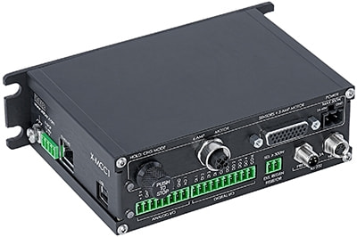
Device Overview
Connectors
All images are shown looking into the device.
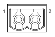
Power
|
Pin | Description |
|---|---|---|
| 1 | 24 - 48 V | |
| 2 | Device GND |
Note: This product requires a CE/UL approved AC/DC power converter such as Zaber's PS13S, PS14S or PS15S with a DC cord of at most 3 m.
Note: As of February 2022, the power supplies Zaber provides are isolated and thus the device is not connected to Earth ground.
If desired, the chassis may be connected to Earth ground with a screw terminal on the dedicated
grounding lugs on MCC and MCB controllers. Prior to 2022, most power supplies were non-isolated. Isolated units can be distinguished by the "S" suffix in their Zaber part number (eg. PS14S), which is marked on the label on the bottom of the power supply.
Multiple Power Supplies:
The X-MCC controller can have multiple power supplies connected (1 per available axis). If not all available axes are supplied directly with power, power is shared between axes. If you wish to use both 48 V and 24 V power supplies for different axes, ensure all axes to be supplied with 24 V are directly powered. For devices using the 6 Amp connector (T11A, T12A), one power supply per axis is required.
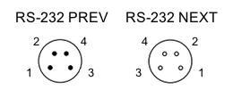
RS-232 Communications
|
Pin | Previous | Next |
|---|---|---|---|
| 1 | Power (max 4 A) | Power (max 4 A) | |
| 2 | Ground | Ground | |
| 3 | Receive | Transmit | |
| 4 | Transmit | Receive |
- Default Settings
- Baud rate: 115200
- Protocol: Zaber ASCII
- Specifications
- Supported Protocols: Zaber ASCII
- Supported baud rates: 9600, 19200, 38400, 57600, 115200
- Bits: 8
- Parity: None
- Stop Bits: 1
- Flow Control: None
Sensor and 3 Amp Motor Interface
 Female High Density D-sub26 Connector |
Pin | Description |
|---|---|---|
| 1 | AutoDetect Clock | |
| 2 | AutoDetect Data | |
| 3 | Encoder Power Enable (BLDC motors) or C Limit Sensor (Stepper motors) | |
| 4 | Away Limit Sensor | |
| 5 | Home Limit Sensor | |
| 6 | Motor Over-Temperature | |
| 7 | Ground | |
| 8 | Motor A2 / Motor V | |
| 9 | Motor A1 / Motor U | |
| 10 | Differential Encoder A+ | |
| 11 | Differential Encoder B+ | |
| 12 | Differential Encoder Index+ | |
| 13 | Differential Encoder Error | |
| 14 | Single-ended Encoder Index | |
| 15 | +5 V | |
| 16 | Ground | |
| 17 | Brake- | |
| 18 | Motor B1 / Motor W | |
| 19 | Differential Encoder A- | |
| 20 | Differential Encoder B- | |
| 21 | Differential Encoder Index- | |
| 22 | Single-ended Encoder A | |
| 23 | Single-ended Encoder B | |
| 24 | Reserved | |
| 25 | Brake+ | |
| 26 | Motor B2 |
The sensor and 3 Amp motor interface is the only connection required for most Zaber peripherals. Certain peripherals with high current motors will feature a separate M12 male connector. For these peripherals, see 6 Amp Motor Interface.
NOTE: The limit sensor inputs are pulled up to an internal supply rail and are designed to be pulled low by an open collector.
NOTE: All single-ended encoder inputs are non-isolated 5 V TTL lines.
NOTE: All differential encoder signals are terminated on the controller with 120 Ω. They are expected to be either RS-422 digital signals with a maximum wave frequency of 10 MHz, or 1 V peak-to-peak analog signals with the common mode of each pair between 1.5 V and 2.5 V.
6 Amp Motor Interface
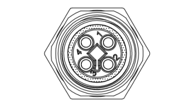
Female T-Coded M12 Connector |
Pin | Stepper Motor Connection | Three Phase Motor Connection |
|---|---|---|---|
| 1 | Motor A2 | Phase V | |
| 2 | Motor A1 | Phase U | |
| 3 | Motor B2 | N/C | |
| 4 | Motor B1 | Phase W |
The 6 Amp motor interface is to be used when the connected peripheral's motor requires more current than the Sensor and 3 Amp Motor Interface can supply. Most Zaber peripherals do not require the 6 Amp motor interface. Peripherals designed to use the 6 Amp motor interface will feature a similar M12 male connector.
NOTE: If using this connector, the four motor pins on the Sensor and 3 Amp Motor Interface must not be used.
NOTE: For devices using the 6 Amp connector, one power supply per axis is required if using a multi-axis controller.
T7 Output Connector
Each X-MCC axis with T7 outputs is shipped with a 1.5 m cable with labeled flying leads. Below is a pinout of the connector on the X-MCC

Note: Exercise caution when connecting the mating connector to the M5 connector.
T8, T15, T16 Output Connector
Each X-MCC axis with T8, T15, and T16 outputs is shipped with a 1.5 m cable with labeled flying leads. Below is a pinout of the connector on the X-MCC.

Note: The ERROR pin is only connected on T8 variants.
Note: There is no Index +/- connection on T16 variants.
E-Stop

|
Pin | Description |
|---|---|---|
| 1 | E-Stop Power (12-48 V) | |
| 2 | E-Stop Ground | |
| 3 | E-Stop Override Input | |
| 4 | E-Stop Override Ground |
E-Stop power inputs are optically isolated, but E-Stop override inputs are not. For details on using the E-Stop, please refer to the dedicated Emergency Stop section.
Mating Products
TE Connectivity 284506-4 or 1986692-4
USB Communications
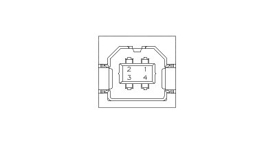
USB Type-B Connector
- Specifications
- USB 2.0 Full Speed
- Communications Device Class, Abstract Control Model
- Default Protocol: Zaber ASCII
- Supported Protocols: Zaber ASCII
Ethernet Communications
- Specifications
- Ethernet (10/100 Mbit/s)
- TCP/IP, TCP Ports: 55550, 55551
- Default Protocol: Zaber ASCII
- Supported Protocols: Zaber ASCII
Digital Inputs/Outputs
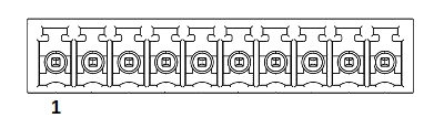
|
Pin | Description |
|---|---|---|
| 1 | Digital In 1 | |
| 2 | Digital In 2 | |
| 3 | Digital In 3 | |
| 4 | Digital In 4 | |
| 5 | Digital In Common | |
| 6 | Digital Out 1 | |
| 7 | Digital Out 2 | |
| 8 | Digital Out 3 | |
| 9 | Digital Out 4 | |
| 10 | Digital Out Common |
| Specifications | Equivalent circuit |
|---|---|
| Maximum Input Voltage (per pin): 8.0 V† | 
|
| Minimum Input Logic High Voltage: 1.5 V | |
| Maximum Output Current (per pin): 3 mA | |
| Maximum Switchable Voltage (per pin): 50 V |
†The input voltage range can be extended with additional series resistance, as described in the I/O Usage and Examples (Digital Inputs) section.
Note: Any cables connected to the I/O port should be limited to 3 m in length.
Mating Products
TE Connectivity 284506-5 or 1986692-5
Analog Inputs/Output
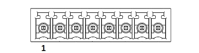
|
Pin | Description |
|---|---|---|
| 1 | +5 V | |
| 2 | Ground | |
| 3 | Analog In 1 | |
| 4 | Analog In 2 | |
| 5 | Analog In 3 | |
| 6 | Analog In 4 | |
| 7 | Ground | |
| 8 | Analog Output |
| Analog Input Specifications | Equivalent circuit |
|---|---|
| Absolute Maximum Input Range (per pin): 0 - 12.8 V | 
|
| Nominal Input Range (per pin): 0 - 10.0 V | |
| Resolution: 0.001 V |
| Analog Output Specifications | Equivalent circuit |
|---|---|
| Analog Output Range: 0 - 10 V | 
|
| Resolution: 2.5 mV | |
| Output Impedance: 100 Ω |
+5 V Output
The +5 V and GND connections can provide power for low-current I/O applications. The pins can source up to 200 mA of current. If additional current is needed, an external power supply is required. Note that this output is not isolated.
Note: Any cables connected to the I/O port should be limited to 3 m in length.
Mating Products
TE Connectivity 284506-8 or 1986692-8
External Regenerative Braking Resistor

|
Pin | Description |
|---|---|---|
| 1 | External Regen + | |
| 2 | External Regen - |
NOTE: Pin 1 is internally connected to the controller's bus voltage, so this pin's voltage will nominally be in the 24-48 V range. During overvoltage transients this voltage may rise to 65 V.
The X-MCC is equipped with an internal regen resistor to assist with energy dissipation during heavy braking events under load. If the braking power in the regen resistor is insufficient, the controller's bus voltage may rise to excessive levels and the controller will be forced to disable the driver. For a single axis under heavy load or multiple axes under moderate load, the internal resistor is usually sufficient to dissipate the generated electrical energy.
For applications with high loads, fast decelerations, and/or multiple axes, an external regen resistor may be required for extra dissipation capacity. In these cases, a resistor rated for 5 Ω and 300 Watts should be connected to the two terminals provided. The required regenerative power for a trapezoidal trajectory may be approximated as 3*m*v*a, where m is the moving mass including the stage top, v is the maximum trajectory velocity and a is the deceleration setting. Please consult Zaber Technical Support to determine if your application may benefit from the addition of an external regen resistor.
Note: Cables to external regenerative braking resistors should be limited to 3 m in length.
Mating Products
TE Connectivity 284506-2 or 1986692-2
Chassis Connection
No portion of the controller operates at voltages exceeding 50 VDC, so the controller is considered a low voltage device and does not need to be explicitly connected to Earth for safe operation. Additionally, Zaber's PS11-PS15 power supplies are non-isolated, thereby already providing a connection from the Ground pin of the power input to Earth. However, if the controller is supplied by an isolated power supply, it may be desirable to ground the metal housing. Signal integrity or application specific safety considerations may also make it desirable to connect the X-MCC's metal frame to the Earth connection shared by the rest of the apparatus. For making grounding connections to the X-MCC frame, attach a 4 mm or 3/16” ring terminal to the provided M4 machine screw as shown below.

Other Connectors
For any connections not described in this document, cables should be limited to a length of 3 m.
Indicators
- Green (Device) - Power
- On: Controller is operational.
- Blinking twice per second: The power supply voltage or controller temperature is out of range.
- Red (Device) - System Error
- On/blinking: An error has occurred. Please contact Zaber Technical Support.
- Yellow (Device) - Communication
- On: Data is being transferred.
- Blinking twice per second: Packet corruption has occurred for ASCII commands sent with a checksum.
- Yellow (Axis) - Axis Status
- On: Peripheral positioner is moving.
- Blinking: Axis is under manual control via the knob (in Velocity mode). The blinking rate is proportional to movement speed.
- Fading in and out every 2 seconds: A connected autodetect peripheral is awaiting activation.
- Blue (Axis) - Axis Warning/Error
- Solid: Peripheral is deactivated.
- Blinking twice per second: Driver is disabled due to over-temperature, out-of-range voltage or other driver fault; due to user request; or due to E-Stop. See Fx Warning Flags. This will also occur briefly when a peripheral is plugged back into the axis after being unplugged or on power-up as device initializes.
- Fading in and out slowly: A peripheral axis is parked. See the tools parking command.
Communications
The X-MCC supports multiple simultaneous communication interfaces. The device will respond to commands on the communication interface which originally sent the message. It will always send alert messages on all available communication interfaces. When multiple communication interfaces are available, only one interface at a time can communicate with daisy-chained devices connected to the RS-232 Next port. Other communication interfaces may also be used to communicate with the device, but their commands will not be forwarded over the Next port. By default, a fixed priority order is used to determine which communication interface may communicate with daisy-chained devices. Alternatively, a specific communication interface may be selected with the comm.next.owner setting.
- Interface Priority
-
- Ethernet
- USB
- RS-232
Daisy Chaining
Daisy Chaining is supported from Ethernet to RS-232 Next, USB to RS-232 Next, and RS-232 Prev to RS-232 Next.
Installation
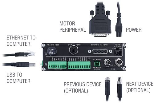
The X-MCC can be connected to a computer as follows:
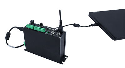
- Connect the controller to the computer with a USB cable (U-DC06), and install the appropriate USB driver (see Appendix B for instructions). You may need to use a cable extension to reach your computer. There is no need to power down or reboot the computer.
- Connect one or more peripherals to the X-MCC controller using the recommended cables. See the Quick Tutorial for more information.
- Connect the power plug of your power supply to the power connector of the device. The green LED should light up indicating the device has power.
- Additional devices can simply be daisy-chained to the first. See Daisy-Chaining Devices below.
- Install software from the Software page. For the initial setup, using Zaber Launcher is recommended.
As a simple first test, try entering:
The parameter of 10000 in the move command above specifies 10000 increments. To see the increment size (default resolution) for the peripheral and how it translates to displacement, first go to the product overview page, find your product, click through to the product's webpage, and click on the "Series Specs" tab. The increment size (default resolution) will be shown in the list of product specs either in the "Group Specifications" section or the "Comparison" section.
Daisy-Chaining Devices
Multiple devices can be connected together in a chain through the Prev and Next connectors. This allows any number of devices to be controlled from a single connection to a computer, reducing cabling demands. In addition, X-Series devices carry power through the daisy chain, so in most cases a power supply only needs to be connected to one device in the chain. Whenever a device is added or removed from a chain, a renumber command should be sent to prevent device address conflicts. If there are device address conflicts, Zaber Launcher will renumber automatically the next time you use it to connect to the chain.
Note: Daisy-chaining devices with cable lengths exceeding 8 m (25 ft) is not recommended.
Physical Installation
The X-MCC is designed to mount to 25mm or 1" pitch optical breadboards using M6 or 1/4" screws, respectively, or for use on a desk or table.
-
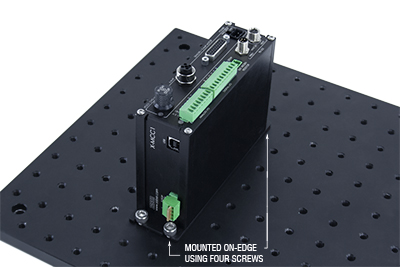
Breadboard mounting controller orientation.
In situations where mounting is not necessary, 4 adhesive rubber feet are provided which can be applied to the underside of the unit to prevent it from sliding on the surface of a desk or table.
-
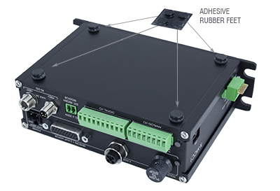
To apply the feet, peel each from the protective backing and place them firmly in the corners on the underside of the unit.
Manual Control
Most X-Series motion control products have an integrated, depressible knob with 20 detents per revolution, allowing axes to be controlled without the use of a computer. There are two manual movement modes available: Velocity and Displacement. Switch between these modes by holding down the knob for 1 second or by configuring the knob.mode setting.
On power-up, many axes will only travel towards the home location from their start-up positions until the home position is reached. Once the axis has been homed, the full range of travel becomes available.
Velocity Mode
Turn the knob clockwise to move the axis in the positive direction (extend) or counter-clockwise for negative direction (retract). Each detent of the knob increases the speed of the carriage.
There are 16 speeds in each direction. The velocity profile and maximum speed can be configured via the knob.speedprofile and knob.maxspeed settings. The axis stops and resets the knob upon arriving at the end of travel.
Displacement Mode
Turn the knob clockwise to move the axis in the positive direction (extend), counter-clockwise for negative direction (retract). Each detent of the knob moves the axis a fixed number of move increments, specified by the knob.distance setting. If knob.distance is set to 0, each detent of the knob will move to the next index position, similar to move index movements. The axis moves at the speed specified by the maxspeed setting, or the slower of maxspeed and limit.approach.maxspeed if the axis has not been homed. If there are fewer than knob.distance move increments to the end of travel and another move is requested, the axis will move to the end of travel and then stop.
Summary of knob functionality
- Turning the knob:
- Moves the axis in the direction of knob turn.
- Pressing the knob:
- Decelerates and stops the axis (identical to a stop command).
- Instantly stops the axis, if the axis is already decelerating.
- Warning: Stopping instantly may result in damage to the product and reduced lifespan. Use sparingly if the axis is under heavy load.
- Pressing and holding the knob for 1 second:
- Toggles between Velocity Mode and Displacement Mode.
Trajectory Control and Behaviour
This section describes the behaviour of the axis trajectory when a movement command is issued.
Software Position Limits
The travel range of the axis is limited by the Minimum Position and Maximum Position settings. Setting a peripheral.id will configure these settings to match the physical travel range. If a customized range is desired, it can be changed by configuring the limit.min and limit.max settings to appropriate values. For the Current Position, query pos.
- Minimum Position
- When the Current Position is less than the Minimum Position value, the axis cannot move in the negative direction.
- Maximum Position
- When the Current Position is greater than the Maximum Position value, the axis cannot move in the positive direction.
Movement Speed
The movement speed of the axis depends on axis status and various speed settings. If the axis has not been initialized by the home command or by moving towards the home end of the axis, movement speed will be constrained to fail-safe values. The home status of the axis can be determined by reading the limit.home.triggered setting.
Movement speed of the axis is specified below:
- move vel
- The axis will move at the specified speed regardless of home status.
- Knob movement in Velocity Mode
- The axis will move at the specified speed regardless of home status.
- The speed is specified by the knob.speedprofile and knob.maxspeed settings.
- Other movement commands - when the axis has not been homed
- The axis will move at the slower of the maxspeed and limit.approach.maxspeed settings.
- Other movement commands - when the axis has been homed
- The axis will move at the speed specified by the maxspeed setting.
Multi-axis Control
X-MCC controllers are available with up to 4 axes of motion, to provide coordinated multi-axis control for gantries and other multi-axis systems. For general information on how to a multi-axis controller, see the protocol manual.
To drive two or more axes in parallel, as in a gantry product, see the protocol reference for lockstep setup and motion commands.
To set up coordinated motion for geometric shapes using multiple axes, see the protocol reference and examples for streams.
I/O Usage and Examples
The X-MCC features a range of flexible input and output options that can be easily examined and controlled from user software. The input and output capabilities of the X-MCC can also be used with triggers to perform actions based on the current value of the I/O channel.
To minimize the number of power supplies needed, the on-board +5 V and GND connections can be used as non-isolated power supplies for I/O circuitry as long as the current draw remains below 200 mA.
Digital Inputs
The digital inputs on the X-MCC are fully opto-isolated and bi-directional, giving added flexibility when interfacing to external equipment. The two examples below demonstrate how the common line can be connected to a power rail or to ground, depending on the application.
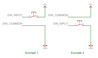
Each digital input contains an internal current limiting resistor of 442 ohms. While this value is suitable for driving the inputs with 5 V (as shown in the circuit above), higher voltages will require the addition of a series resistor. A list of recommended values for the external resistor and example circuit are shown below.
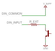
| V_SUPP (V) | R_EXT (Ohms) | Power (mW) |
|---|---|---|
| 0 - 8 | 0 | n/a |
| 8 - 15 | 500 | 125 |
| 15 - 24 | 1500 | 250 |
The circuit above also shows how to interface with an open collector output from another device. Reading the inputs is accomplished by sending the unit an io get command, as shown below.
/1 io get di

@01 0 OK IDLE -- 0 0 1 0
/1 io get di 1

@01 0 OK IDLE -- 0
The first command queries all inputs on the device and shows that input 3 is "on" (not equal to the common line) and all others are "off" (equal to the common line). Depending on whether your common line is connected to ground or a positive voltage, "on" might mean a high or a low voltage level. The second command queries a specific input on the device, in this case input 1, which is "off".
Digital Outputs
All digital outputs on the X-MCC are fully opto-isolated and capable of sinking a minimum of 3 mA at up to 50 V. The first example circuit below shows how to drive an LED from one of the digital outputs. In order to switch loads with a higher current draw, for example a relay, an external switching transistor is required, as shown in example 2.
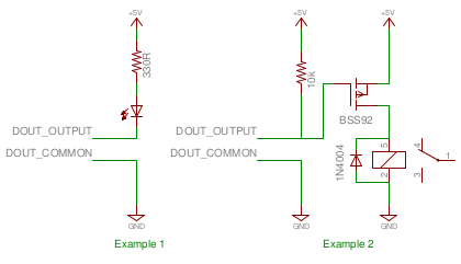
The digital outputs are set through the io set command, as shown below.
/1 io set do 1 1

@01 0 OK IDLE – 0
/1 io set do 1 0

@01 0 OK IDLE – 0
The first command sets the first digital output "on", which would cause the LED in example 1 above to glow. The second command turns "off" the output, turning off the LED.
TTL Outputs
Additional circuitry is required to get TTL signal levels from the X-MCC, as shown below.
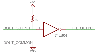
The 74LS04 contains 6 inverters so it is possible to convert all of the digital outputs with one IC. In order to maintain isolation, it is recommended that the 5 V and GND supply connections come from the device requiring the TTL signalling. It is, however, possible to use the 5 V and GND connections from the Analog Output connector on the X-MCC to power the external device, as long as the current limits are adhered to.
Analog Inputs
The analog inputs on the X-MCC accept and display voltages in the range of 0 – 10 V. In order to measure other analog variables, a transducer or sensor is required that outputs an appropriate voltage range. As transducers typically provide low voltage signals, an amplifier and buffer circuit is required to interface a transducer to the X-MCC.
The reference circuit below demonstrates how to connect a wheatstone bridge to one of the analog inputs on the X-MCC. Various instruments are configured in a wheatstone bridge arrangement, including load-cells and strain gauges.
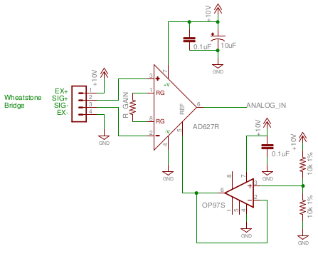
R_GAIN's value should be chosen so that a positive full scale of the instrument produces 10 V at the analog input of the X-MCC and a negative full scale produces 0 V. The OP97 op-amp provides an offset of 5 V to the amplified value so that no load on the instrument produces an output of 5 V.
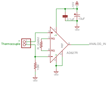
The reference circuit below demonstrates interfacing a thermocouple to the X-MCC. Depending on the application, an offset voltage may need to be provided.
Analog Output
The analog output channel on the X-MCC is non-isolated, and has a range of 0 to 10 V. The output impedance of the line is 100 Ω.
The nominal analog output resolution is 2.49755859 mV, and the requested value should be specified in Volts with up to three decimal places. The actual output will be set to the nearest resolution increment, rounded down. The analog output is set through the io set command, as shown below.
/1 io set ao 1 4.625

@01 0 OK IDLE -- 0
/1 io get ao 1

@01 0 OK IDLE -- 4.622
The first command requests the first and only analog output (AO) channel to be set to 4.625 V. The second command queries the set point of the first analog output channel, and returns the set point floored to three decimal places.
Emergency Stop
The X-MCC is equipped with an optional 4 pin Emergency Stop input.
A voltage between 12-48 V must always be applied to the two E-stop power inputs. When the E-stop input is de-energized, the X-MCC produces a Safe Torque Off (STO) response on all motion axes. STO is characterized by removing power from the motor (ie. disabling the driver) and allowing the positioner to coast to an uncontrolled stop. The controller will still be active in this state and remain responsive to queries and commands. The motor will remain unpowered until the E-stop input is re-energized and the driver is re-enabled with a driver enable command.
 WARNING: Safe Torque Off is not recommended for all usage cases since an uncontrolled, unpowered stop may result in unsafe behavior.
WARNING: It is the user’s responsibility to evaluate the safety of their overall application and put in place the correct safety features. For example, applications with high speeds or heavy loads or vertical motion may require an external braking system to ensure that the load is safely stopped during an E-stop event. All safety features must be tested in controlled, non-dangerous situations to ensure they will work properly during a real E-stop event.
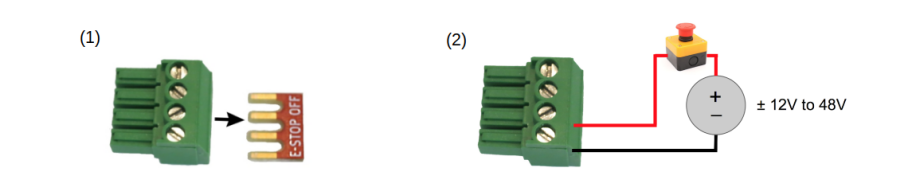
The X-MCC ships with a shorting bar across all four interface pins to disable the E-stop by default and allow normal motor operation. To use the E-stop circuit, first remove the shorting bar and then wire a DC power supply with a voltage of between 12 V and 48 V in series with a normally closed switch as shown below. The signal can be wired in either polarity. Opening the switch will cause the E-stop to engage.
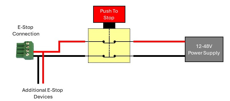
Shown below is a straightforward circuit to integrate the X-MCC and additional devices with a 2 circuit normally closed (NC) switch, similar to Zaber’s ES01 accessory. The E-Stop will be activated when the switch is pressed, opening the circuit.
Power-Off Brake Control
- Power-off brake control is available for X-MCC (revision 2+) with firmware 7.34+.
Brake Settings: The brake must be correctly configured in order to operate correctly. In Zaber’s controllers, there are multiple settings that affect correct operation. The default settings for the X-MCC product may need to be modified for some applications. When modifying these settings, be sure to follow the guidance in the Protocol Manual.
Described below are the recommended procedures for operating a brake-equipped device:
- Dynamic Brake Engagement - For Position Holding After Faults
- The power-off brake opens by default when the system is powered up. The brake will close if the device stalls, is displaced while stationary, the driver is disabled, or the power is interrupted. Repeated dynamic stopping may reduce the lifetime of the brake. We strongly recommend avoiding dynamic braking when possible.
- Stationary Brake Engagement - For Position Holding
- The power-off brake opens by default when the system is powered up. To change the brake state, use brake.mode.
- The order of operations to set a retaining position should follow:
- Open the brake by setting brake.mode to 1.
- Allow 100 ms for the brake to open.
- Move the positioner.
- Close the brake by setting brake.mode to 0.
- Allow 100 ms for the brake to close.
- If accuracy is required, the driver.current.hold (T:39) should remain on to prevent slight shifts in the device position.
- Stationary Brake Engagement - For Reducing Motor Heat
- The power-off brake opens by default when the system is powered up. To change the brake state, use brake.mode. To reduce heat generated in the motor, use the driver disable command in between moves.
- The order of operations to maintain a vertical position, and disabling the driver to reduce heat, should follow:
- Set the hold current to the appropriate value based on load (see defaults on website).
- Move the positioner to the intended location.
- Send the driver disable command. The brake will automatically close.
- When ready to move again, send the driver enable command. The brake will open.
- Move the positioner as normal
- Turning off the hold current will cause a small displacement of the positioner.
- Manual Device Movement
- Manual Device movement requires disabling the encoder displacement detection to prevent engagement of the power-off brake. The order of operations for manual movement should follow:
- Remove any load from the positioner.
- Disable closed-loop control by setting cloop.enable to 0 .
- Set the hold current to 0.
- Move the positioner manually by hand. For screw driven linear devices, turning the lead screw can assist in achieving smaller increments during manual movement.
Encoder Outputs
The X-MCC is optionally available with encoder outputs. Encoder outputs are available to work with all Zaber encoder types, with options for either a single-ended output or differential output, depending on the application's requirements. There are four options for encoder output on the X-MCC, which can be selected based on what type of encoder the peripheral has and the desired output.
| Output Option | Peripheral Encoder Type | Digital Output Signal Type |
|---|---|---|
| T7 | Single-Ended Shaft Encoder (-E) | Single-ended quadrature |
| T8 | Analog Differential Encoder (-AE) | Differential quadrature, configurable resolution |
| T15 | Digital Differential Encoder (-DE) | Differential quadrature, fixed resolution |
| T16 | Single-Ended Shaft Encoder (-E) | Differential quadrature, fixed resolution |
Typical applications for encoder output access include line cameras, 3D scanners using lasers, and line printing. These outputs can also be used with quadrature encoder readers to synchronize encoder data with other data acquisition.
Part Number Information

Outputs are installed starting on the highest numbered axes. For example, on an X-MCC4-T7N2, single-ended shaft encoder outputs are made available on axes 4 and 3.
Signals and Wiring
Output Signals
- The A and B channels are digital quadrature signals driven at 5 V. The two channels are out of phase by 90 degrees, allowing both position and direction to be determined. In some encoder output variants, these signals are made differential and are labeled as A+, A-, B+, and B-.
- The index signals (Index+/-) give a single count per length of encoder travel (cycle length), and operate on 0-5 V. The Index+ signal will output a HIGH (+5 V) signal when passing over an index mark internal to the device, and the Index- signal will go LOW (0 V). This signal can be used to count revolutions, for homing, and more.
Differential Pair Termination
All differential pairs should be terminated with a 120 resistor between the + and - channels to achieve the lowest noise signals. The resistor should be sized to handle a minimum of 0.25 W. This resistor should be connected close to the acquisition device for optimal performance.
If the encoder count reader/acquisition device uses a single-ended input, the termination resistor should still be connected across the differential signals, and the positive channel should be connected to the single-ended input.

Single-ended Encoder to Single-ended Output (T7)
T7 outputs are available on Zaber devices that use single-ended shaft encoders (labeled -E). Devices with T7 outputs produce a single-ended digital output via a 4-pin M5 connector on the X-MCC.
Single-ended Encoder to Differential Digital Output (T16)
T16 outputs are available on Zaber devices that use single-ended shaft encoders (labeled -E). Devices with T16 outputs produce a differential digital output via an 8-pin M8 connector on the X-MCC. These differential outputs are communicated via RS-422.
Differential Digital Encoder to Differential Digital Output (T15)
T15 outputs are available on Zaber devices that use differential digital encoders (labeled -DE), and produce a differential digital output. Devices with T15 outputs produce a differential digital output via an 8-pin M8 connector on the X-MCC. These differential outputs are communicated via RS-422. These outputs are non-configurable, and output encoder counts at a fixed rate of 10 MHz. Encoder counts must be read at a minimum of 10 MHz, regardless of the speed of axis movement. Encoder counts will be missed, and drift will occur (even when the axis is stationary) if attempting to read at less than 10 MHz.
Differential Analog Encoder to Interpolated Differential Digital Output (T8)
T8 outputs are available on Zaber devices that use differential analog encoders (labeled -AE), and produce an interpolated differential digital output, allowing for position resolution from 5 µm down to 4.88 nm. These differential outputs are communicated via RS-422.
The output interpolation factor and minimum output time are configurable on the X-MCC via user commands (refer to the Zaber ASCII Protocol Manual). See Selecting Interpolation Parameters below for details on how to select parameters for your application.
Selecting Interpolation Parameters
There are three important parameters to consider when configuring interpolation on T8 devices. Maximum desired axis speed, interpolation factor, and minimum output time width are related by the following equation:
Note: the “maximum axis speed” defined here is not the same speed as the axis’ absolute maximum speed setting (maxspeed) on the device. The axis may be able to exceed this speed, but encoder outputs will not be correctly generated above the maximum axis speed.
The cycle length for all Zaber -AE devices is 20 µm, but the maximum axis speed, interpolation factor, and minimum output time width can be set according to the application’s needs by the user.
The interpolation factor determines the resolution of the encoder output, and the minimum output time width determines the frequency at which encoder counts must be able to be read at by the user sampling system (i.e., a DAQ). Encoder count read frequency and minimum output time width are inversely proportional. Thus, if the minimum output time is set to 1000 ns, encoder counts must be able to be read at a frequency of 1 MHz. If encoder counts can not be read at this frequency, counts will be missed and there may be drift in the count, even when the axis is at rest.
The plot below shows the relationship between these parameters. For a full list of the allowable values for these parameters on Zaber devices, refer to the Zaber ASCII Protocol Manual. More detailed information about how to select these parameters can be found below.

- The interpolation factor is the number of quadrature counts (quarter cycles) generated at the output per full cycle of the analog encoder. For example, a value of i = 4 performs no interpolation, merely digitizing the analog encoder signal; this generates one full cycle (four counts) of output per full cycle of the analog encoder. Larger values increase the output resolution by interpolating the analog levels to generate additional counts.
- The minimum output time width is the time in nanoseconds between a transition on either of the A or B interpolated analog encoder output signals (as shown below) and the next transition on either of those signals. For example, a value of 25 means that, after any transition appears on either the A or B output, at least 25 ns will pass before any more transitions appear on either A or B output. A transition on either of these channels indicates an encoder count increment or decrement.
- The interpolation factor and minimum output time define the maximum speed at which the axis can move at such that no encoder counts will be missed. For example, with an interpolation rate of i = 8 and a minimum output time of w = 3200 ns, the stage will have a maximum allowable speed of
Note: All Zaber -AE devices have a cycle length of 20 µm

Missed Encoder Counts
- Referring to the example above, if the maximum axis speed of 0.78 m/s is exceeded, a transition will occur in the interpolated output before the interpolator is ready for the next encoder count, thus missing an encoder count. This behaviour is shown in the plot below, where the speed of the stage is doubled from 0.5 m/s to 1 m/s. This doubles the frequency of the analog encoder input and of the interpolated digital output. The minimum output time width is set to 3.2 µs, but a transition occurs in 2.5 µs. Thus, an encoder count is missed.
- The ERROR pin is driven by an open-drain driver with an internal pull-up resistor. The ERROR signal is set LOW (0 V) if an encoder count is missed, indicating the maximum output speed has been exceeded. The ERROR pin will stay active (LOW) for at least 50 ms upon a missed encoder count.
- In addition to ensuring axis speed is below the maximum, the encoder count reader that reads this digital signal must be able to read as fast as encoder counts are generated. For this example, since at the maximum axis speed an encoder count is generated every 3200 ns, the counter must be able to read at 1/3200 ns = 312.5 kHz.

Current Controller Tuning
In firmware versions 7.27 and up, this product's current controller can be tuned to modify the performance of stepper motor peripherals. The current controllers on Zaber products are already tuned to perform well in the vast majority of situations. You should only need to tune the current controller if the default tuning is not providing sufficient performance, or if you are configuring a non-Zaber peripheral.
Use the Current Tuner application in Zaber Launcher to tune the performance of the motor.
Non-Zaber Peripheral Support
In firmware versions 7.27 and up, the X-MCC is capable of supporting a wide range of third party stepper motor peripherals. This includes:
- linear or rotary products
- up to three limit sensors
- up to one position encoder
Use the Advanced Hardware Setup application in Zaber Launcher to configure a non-Zaber peripheral.
Motors
The bipolar stepper motor driver can drive 2-phase bipolar and unipolar stepper motors at up to 48 V. Unipolar motors are driven in a bipolar configuration with the winding center taps disconnected.
Limit Sensors
Each sensor can be active high or active low but must use either 3.3 - 5 V TTL/CMOS logic, be open collector, or switch to ground.
Encoders
A wide range of position encoder features are supported, including:
- single-ended or differential signaling
- digital or analog signaling
- up to one index mark
- up to one fault signal
- digital filtering and/or interpolation
The differential encoder inputs have a 120 ohm impedance. Single-ended encoders must use 3.3 - 5 V logic, digital differential encoders must be RS422 compatible, and analog differential encoders should have a nominal voltage of 1 Vpp (maximum 1.35 Vpp).
Troubleshooting X-Series Motion Devices
The following sections contain tips for troubleshooting common problems. If the device is unable to communicate, and it is operating erratically, a manual factory reset can be performed on most devices using the following steps. Note that this will reset most settings.
- Power Off the device
- Push and hold the knob for the first Axis (if applicable)
- Power On the device
- Continue to hold the knob in (for ~5 seconds) until one or more LEDs are fading or the blue LED is lit, then release.
- The device has been returned to its factory defaults and can be configured as per the steps in Initial Setup.
Front Panel Indicators
- Green LED on.
- The device is powered on and is operating normally.
- Green LED flashes slowly.
- The operating conditions of the device are outside of the recommended range.
- This will occur when the supply voltage is either over or under the recommended range or the controller temperature has exceeded the set limit. Check the following:
- The input voltage is within the operational range of the device. This can be read from the device with the get system.voltage command.
- The device temperature is within range. This can be read from the device with the get system.temperature command.
- Green LED off.
- The device is not powered.
- Check the supply connections and power adaptor for correct operation.
- Red LED on or flashing.
- A critical error has occurred.
- Please contact Zaber Technical Support.
- Yellow LED always off or flashes but no reply.
- There are communication errors.
- Please see the Communication Errors section below.
- Yellow LED fading in and out.
- A peripheral is awaiting activation.
- Please see the Activating Peripherals section.
- Blue (or Green for Firmware versions <7.15) LED fades in and out (stepper motor peripherals only).
- The axis is parked.
- Issue a tools parking unpark command, or home the axis.
- Blue LED flashing during a move or blinking every two seconds.
- The axis has slipped or stalled.
- Please see the Slipping and Stalling section below.
- Blue LED showing a burst of 2 flashes every 1 second
- A stationary axis has been forced out of position.
- Blue LED showing a burst of 5 flashes every 2 seconds.
- The encoder has encountered a read error.
- Please contact Zaber Technical Support.
- Blue LED blinking twice per second. Axis does not move.
- Driver may be disabled due to over-temperature, out-of-range voltage or other driver fault; or due to user request.
- See Fx Warning Flags.
- Once the issue has been resolved, send driver enable.
- This will also occur briefly when a peripheral is plugged back into the axis after being unplugged.
Manual Control
- Turning the knob either way results in no movement.
- The knob may have been disabled.
- Check that the knob.enable setting is correct.
- Restore the default parameters through the system restore command.
- A brake-equipped axis does not move under manual control.
- The power-off brake may be closed.
- Ensure that brake.mode is set to 1.
- The axis won't cover the full range of travel.
- The axis hasn't been homed.
- Turn the knob anti-clockwise until the axis reaches the fully retracted position. The axis will home and the full range of travel available.
Unexpected Behaviour
- The axis doesn't respond to a move command.
- The axis may need to be homed before use.
- Send the home command.
- A move command is rejected
- The power-off brake may be closed.
- Ensure that brake.mode is set to 1.
- A peripheral won’t move and move commands are rejected.
- The peripheral may have been unplugged and plugged back in to the wrong axis. Send the activate command the peripheral to continue using it.
- The axis is moving on its own and running against the ends of travel.
- The position encoder has de-synchronized.
- Reset the device by power cycling it or sending the system reset command, then re-initialize it with the home command.
- The axis is moving very slowly. It used to move faster.
- The speed settings may have been changed inadvertently.
- Send a system restore command.
- The axis makes louder than normal noise during travel and is frequently slipping.
- This condition happens if the thrust needed is more than the thrust available from the axis.
- Check the following:
- The force on the axis is less than the maximum thrust.
- The voltage matches the specified voltage. Read the voltage using the get system.voltage command. Voltage less than the specified voltage for the device will reduce the positioner’s maximum thrust.
- Test the following:
- Try a slower target velocity.
- Try a lower acceleration and deceleration.
- For ball/lead screw products, clean the screw and review the Precautions section for information on whether to apply any lubrication.
- A stepper motor peripheral has repeatability errors smaller than 4 full steps.
- If steps aren't being skipped, friction or loose parts may still cause some variation when returning to a position.
- Please contact Zaber Technical Support.
- The axis doesn't cover the full range of travel, or runs into the end.
- A setting might have been inadvertently changed.
- home the axis to see if this corrects the behaviour.
- Send a system restore command.
- Ensure that the peripheralID setting of each axis corresponds to the attached positioner. A list of peripheral ids are available at the Peripheral IDs page.
- The positioner's motor unexpectedly shuts off. An Fx warning flag is present.
- The motor over-temperature protection switch has been tripped. This sensor will trip if the positioner's maximum continuous thrust specification is exceeded for too long. To prevent this condition from occurring again, reduce the average force that the motor outputs by reducing acceleration, reducing the load, or lowering the duty cycle.
- Send a driver enable command. The axis does not require homing.
Encoder Output Behavior
- Encoder outputs are not functioning.
- Ensure that the Encoder Output setting (encoder.2.out.enable) is enabled (set to 1).
- There are significant voltage spikes or noise on differential encoder signals.
- Ensure they are terminated with a 120 Ω resistor. The resistor should be sized to handle a minimum of 0.25 W. This resistor should be connected close to the acquisition device for optimal performance.
Power-Off Brake Unexpected Behaviour
- Brake isn’t opening on brake.mode 1.
- An audible click should be heard when the brake is switching from closed to open. If no click is detected during brake mode transition, please contact Zaber Technical Support.
- Power-off brake is hot to touch.
- A significant amount of heat is generated during normal operation of the device, and care should be taken to avoid potential burns to the operator and damage to the device components.
- If there are Driver Temperature (DT) or Temperature High (WT) warning flags, reduce the duty cycle and the driver.current.run (T:38) where possible.This will help prevent overheating and improve brake lifetime.
- Please contact Zaber Technical Support to help select the optimal duty cycle and current settings for your device.
Communication Errors
- There is no communication with the device; the Yellow LED does not come on or flash.
- There are several things that should be checked:
- Make sure the correct serial port is selected. Try selecting other serial ports in the software.
- Check the baud rate, hand shaking, parity, stop bit, etc. when configuring the serial communications software. The required settings are listed in the RS-232 Communications section above.
- Make sure there are no bent pins in the ends of all the data cables
- Make sure the device is powered. The Green LED should be on.
- If the computer is a laptop running on batteries, try plugging in the power. Some laptops disable the serial ports when running on batteries.
- Make sure a null modem adaptor or cable is not being used.
- Make sure the correct adaptors (if any) are being used. Refer to the pinouts in the RS-232 Communications section above.
- If the problem was encountered when trying to control the device with custom software, try using Zaber Launcher to verify that the hardware is functioning properly.
- Two or more devices both respond to commands sent to device 1.
- Most devices are shipped with their device number set as 1. If you connect to the devices with Zaber Launcher, it will automatically renumber them if needed. If you aren't able to install and open Zaber Launcher, send the renumber command in the software you are using to set all of the device numbers to different values.
- The Yellow LED comes on briefly when sending a command, but the axis does not move and does not reply.
- Check baud rate, hand shaking, parity, stop bit, etc. are set as per the RS-232 Communications defaults.
- The device numbers may not be what is expected, issue a renumber command. Make sure that the computer does not transmit anything else while the devices renumber.
Slipping and Stalling
- The device moves smoothly, but only moves for a short time then stops. The Blue LED is flashing but the axis is not actually slipping or stalling.
- The internal encoder counter needs to be re-initialized. Reset the device by power cycling it or sending system reset command. Ensure the power-off brake is open (brake.mode.1), then re-initialize the device with the home command.
- Ground the device and avoid operating it under statically noisy environment.
- The axis makes noise but does not move. The Blue LED is flashing.
- The axis is stalling and the brake has closed. Move commands are rejected when the brake is closed. To resume operation after a stall, open the brake by sending a driver enable command.
- Try removing all external loads. If the axis now extends and retracts normally, the problem is excessive load. Try to reduce the load and ensure the load is less than the maximum thrust. A higher thrust or torque can be achieved by lowering the speed of the axis using the maxspeed setting.
- If an axis is stalling with no external load at default speed and acceleration settings then it requires servicing.
Warranty and Repair
For Zaber's policies on warranty and repair, please refer to the Ordering Policies.
Standard products
Standard products are any part numbers that do not contain the suffix ENG followed by a 4 digit number. Most, but not all, standard products are listed for sale on our website. All standard Zaber products are backed by a one-month satisfaction guarantee. If you are not satisfied with your purchase, we will refund your payment minus any shipping charges. Goods must be in brand new saleable condition with no marks. Zaber products are guaranteed for one year. During this period Zaber will repair any products with faults due to manufacturing defects, free of charge.
Custom products
Custom products are any part numbers containing the suffix ENG followed by a 4 digit number. Each of these products has been designed for a custom application for a particular customer. Custom products are guaranteed for one year, unless explicitly stated otherwise. During this period Zaber will repair any products with faults due to manufacturing defects, free of charge.
How to return products
Customers with devices in need of return or repair should contact Zaber to obtain an RMA form which must be filled out and sent back to us to receive an RMA number. The RMA form contains instructions for packing and returning the device. The specified RMA number must be included on the shipment to ensure timely processing.
Email Updates
If you would like to receive our periodic email newsletter including product updates and promotions.
Contact Information
Contact Zaber Technologies Inc by any of the following methods:
| Phone | 1-604-569-3780 (direct) 1-888-276-8033 (toll free in North America) |
|---|---|
| Fax | 1-604-648-8033 |
| #2 - 605 West Kent Ave. N., Vancouver, British Columbia, Canada, V6P 6T7 | |
| Web | www.zaber.com |
| Please visit our website for up to date email contact information. |
The original instructions for this product are available at https://www.zaber.com/manuals/X-MCC.
Appendix A - Available Communications Ports
The following instructions outline how to find installed serial ports on your computer.
Windows
- Open Search or Run from the Start Menu or Taskbar, type "Device Manager" and press enter.
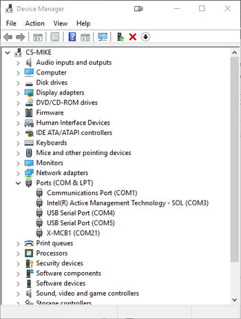
- Expand the Ports (COM & LPT) category.
- In this example there are two serial ports available (COM1 and COM15), which are both USB adaptors.


Linux
- Finding devices
- Open a terminal and execute the following command:
- dmesg | grep -E ttyU\?S
- The response will be similar to the following:
[ 2.029214] serial8250: ttyS0 at I/O 0x3f8 (irq = 4) is a 16550A
[ 2.432572] 00:07: ttyS0 at I/O 0x3f8 (irq = 4) is a 16550A
[ 2.468149] 0000:00:03.3: ttyS4 at I/O 0xec98 (irq = 17) is a 16550A
[ 13.514432] usb 7-2: FTDI USB Serial Device converter now attached to ttyUSB0 - This shows that there are 3 serial ports available: ttyS0, ttyS4 and ttyUSB0 (a USB adaptor)
- Checking port permissions
- Using the ports found above, execute the following command
- ls -l /dev/tty{S0, S4, USB0}
- The permissions, given below, show that a user has to be root or a member of the dialout group to be able to access these devices
crw-rw---- 1 root dialout 4, 64 Oct 31 06:44 /dev/ttyS0
crw-rw---- 1 root dialout 4, 68 Oct 31 06:45 /dev/ttyS4
crw-rw---- 1 root dialout 188, 0 Oct 31 07:58 /dev/ttyUSB0
- Checking group membership
- groups
- The output will be similar to the following:
adm cdrom sudo dip plugdev users lpadmin sambashare
Notice that dialout is not in the list - A user can be added to the dialout group with the following command
- sudo adduser $USER dialout
- Group membership will not take effect until the next logon.
- groups
OSX
- Finding devices
- Open a terminal and execute the following command:
- ls /dev/cu.*serial*
- The response will be similar to the following:
/dev/cu.usbserial-FTB3QAET
/dev/cu.usbserial-FTEJJ1YW - This shows that there are two serial ports available, both of which happen to be USB adaptors.
- There may be other devices that match this query, such as keyboards or some web cameras. To determine which one corresponds to your USB serial cable, try repeating the command with and without the cable connected to the computer, to see which one appears and disappears.
Appendix B - USB Driver Installation

Compatible Devices
The following Zaber controllers include a USB 2.0 Type-B port:
- E-MCC Series
- X-MCC Series
- X-MCB Series
- A-MCB Series
When connected and configured following the instructions on this page, they will create a virtual serial (COM) port on your computer for communication.
If you are trying to connect one of Zaber's X-USBDC, T-USBDC, or T-USB serial to USB adaptors, go to the Software page Troubleshooting section for instructions.
Windows
Prior to Windows 10, a driver was required for the USB connection to operate correctly. With Windows 10, installing the driver is not necessary but can be done so that the name of the controller is identified alongside the COM port.
Download
- Download the driver here: Zaber Integrated USB Driver.
- Extract the files to a handy location: Downloads, My Documents or the Desktop are good places.
- Connect power to the controller and connect the USB cable from the controller to the computer.
- Follow the additional steps for your version of Windows.
Windows 10
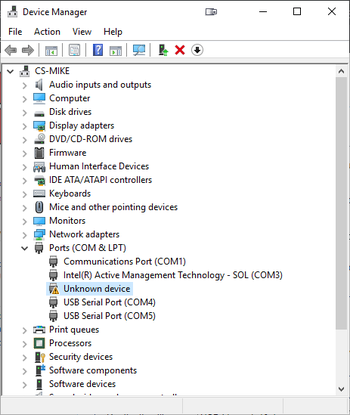
- Right click on the Start button and select Device Manager.
- Under 'Ports (COM & LPT)', you should see an entry with the name 'Unknown device'.
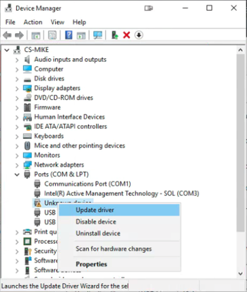
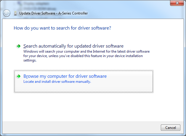
- Right click on this entry and select 'Update Driver'.
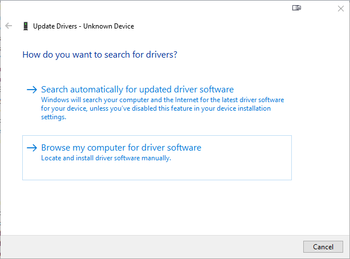
- Choose 'Browse my computer for driver software'.
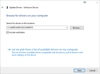
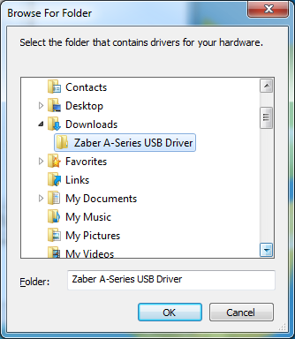
- Click the Browse button and select the location where you extracted the driver to.
- Click Next.
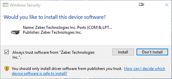
- Click Install.
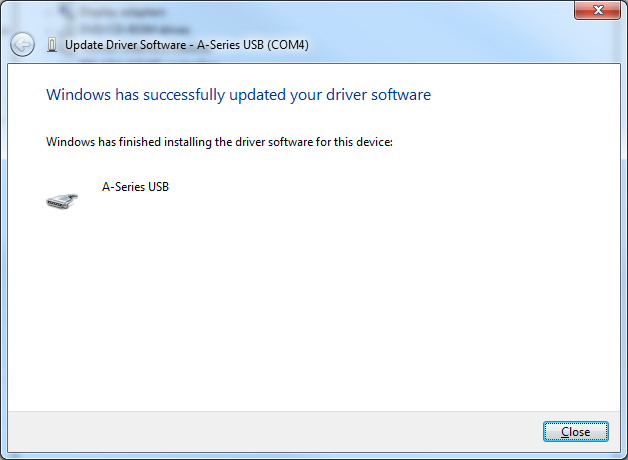
- Click Close. Your controller is now available and should appear in the 'Ports (COM & LPT)' section of the Device Manager.
Windows Vista, 7 & 8
- Windows will detect the device connection and attempt to automatically install drivers. After a minute or so this will fail with a message that the device is not working correctly. Continue on with the steps below.
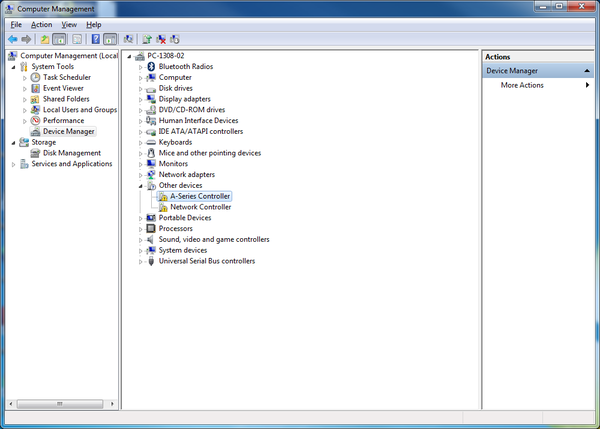
- Right click on My Computer and select Manage.
- Select Device Manager from the list on the left. Under 'Other devices', you should see an entry with the name of the Zaber controller that is connected.
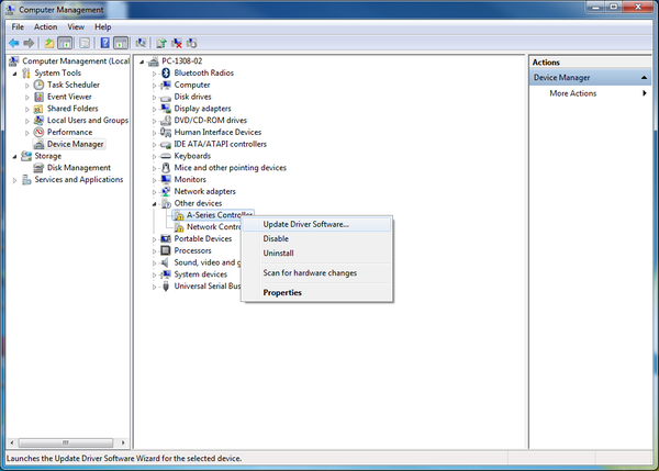
- Right click on this entry and select 'Update Driver Software...'
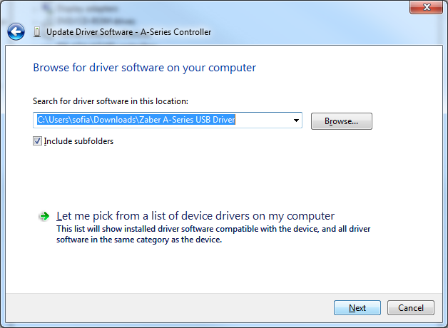
- Choose 'Browse my computer for driver software'.
- Click the Browse button and select the location where you extracted the driver to.
- Click Next.
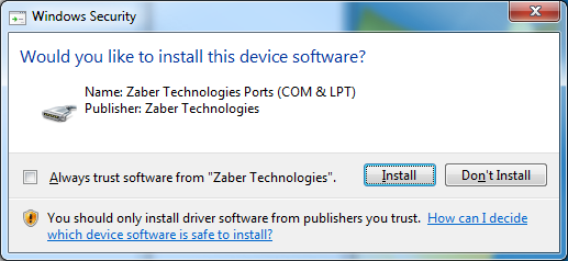
- Click Install.
- Click Close. Your controller is now available and should appear in the Ports (COM & LPT) section of the Device Manager.
Windows XP
- Windows will automatically detect the connection of the controller.
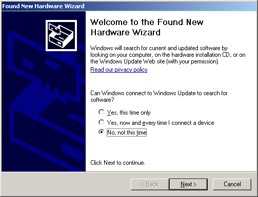
- Once the New Hardware Found wizard starts, select 'No, not this time' and click next.
- If the wizard doesn't start:
- Right click on My Computer and select Manage.
- Select Device Manager from the list on the left.
- Under 'Unknown Devices', you should see an entry with the name of the Zaber controller that is connected.
- Right click on this entry and select 'Update Driver'.
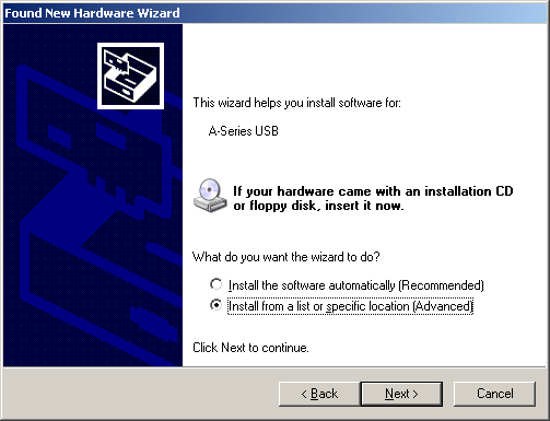
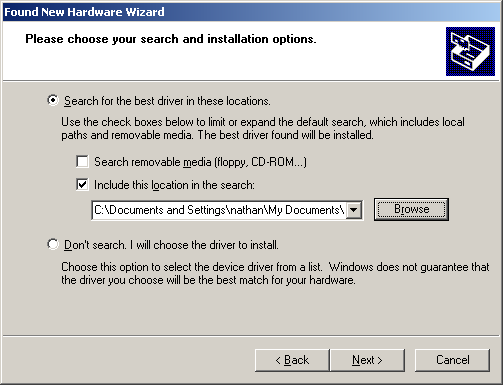
- Select 'Install from a specific location' and click Next.
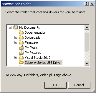
- Click the Browse button and select the location where you extracted the driver to.
- Click Next.
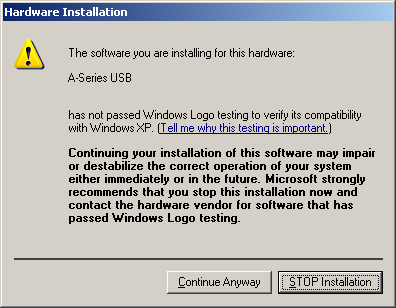
- Select Continue Anyway.
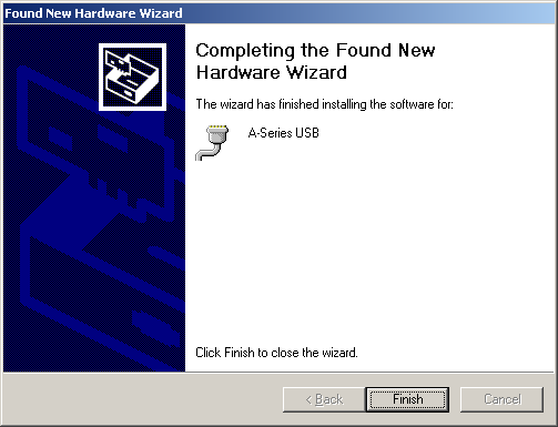
- Click Finish. Your controller is now available and should appear in the Ports (COM & LPT) section of the Device Manager.

Linux
USB Communications Device Class (CDC) devices are supported in kernel 2.4 and above through the cdc_acm module. No special configuration or drivers are needed.
The controller will appear as a ttyACMx device. The kernel log (available through dmesg) details the device detection and the assigned device, in this case /dev/ttyACM0
[94929.668171] usb 3-4.1.3: new full-speed USB device number 92 using xhci_hcd

[94929.686563] usb 3-4.1.3: New USB device found, idVendor=2939, idProduct=cafe

[94929.686572] usb 3-4.1.3: New USB device strings: Mfr=1, Product=2, SerialNumber=3

[94929.686577] usb 3-4.1.3: Product: X-MCB2

[94929.686581] usb 3-4.1.3: Manufacturer: Zaber Technologies Inc.

[94929.686585] usb 3-4.1.3: SerialNumber: 1

[94929.687436] cdc_acm 3-4.1.3:1.0: This device cannot do calls on its own. It is not a modem.

[94929.687471] cdc_acm 3-4.1.3:1.0: ttyACM0: USB ACM device
If the device does not appear in the /dev directory when connected, the device may need to be manually attached. To do this, enter the commands below corresponding to your controller:
| E-MCC3 | echo "0x2939 0x49e3" > /sys/bus/usb/drivers/cdc_acm/new_id |
| E-MCC2 | echo "0x2939 0x49e2" > /sys/bus/usb/drivers/cdc_acm/new_id |
| E-MCC1 | echo "0x2939 0x49e1" > /sys/bus/usb/drivers/cdc_acm/new_id |
| X-MCC4 | echo "0x2939 0x49c4" > /sys/bus/usb/drivers/cdc_acm/new_id |
| X-MCC3 | echo "0x2939 0x49c3" > /sys/bus/usb/drivers/cdc_acm/new_id |
| X-MCC2 | echo "0x2939 0x49c2" > /sys/bus/usb/drivers/cdc_acm/new_id |
| X-MCC1 | echo "0x2939 0x49c1" > /sys/bus/usb/drivers/cdc_acm/new_id |
| X-MCB2 (FW7) | echo "0x2939 0x49b2" > /sys/bus/usb/drivers/cdc_acm/new_id |
| X-MCB1 (FW7) | echo "0x2939 0x49b1" > /sys/bus/usb/drivers/cdc_acm/new_id |
| X-MCB2 (FW6) | echo "0x2939 0x495b" > /sys/bus/usb/drivers/cdc_acm/new_id |
| X-MCB1 (FW6) | echo "0x2939 0x495a" > /sys/bus/usb/drivers/cdc_acm/new_id |
| A-MCB2 | echo "0x2939 0x459" > /sys/bus/usb/drivers/cdc_acm/new_id |
Note: In some configurations, modem manager will try to query the device when it is connected. This won't affect device operation but can cause the port to be unavailable for several seconds.
OS X
USB Communications Device Class (CDC) devices are supported in 10.5 and above. No special configuration or drivers are needed.
The controller will appear as a tty.usbmodem device. The kernel log (available through dmesg) details the device detection and the assigned device, in this case /dev/tty.usbmodem1421
AppleUSBCDCACMData: Version number - 4.1.23, Input buffers 8, Output buffers 16

AppleUSBCDC: Version number - 4.1.23

$ ls /dev/tty.usb*

/dev/tty.usbmodem1421
Appendix C - Ethernet Setup
By default, the Ethernet communication interface uses DHCP to obtain an IP address automatically. This is the easiest way to use the Ethernet communication interface and does not require any configuration before connecting to an existing network which has a DHCP server available.
Alternatively, to manually configure a static IP address, subnet mask, and default gateway address, use the <comm en ipv4 static> command. This command can be sent over any available communication interface, such as USB or RS-232.
The following example describes how to use the USB or RS-232 communication interface with Zaber Launcher to configure Ethernet for a network which uses the following (sample) static configuration details:
| IPv4 address: | 192.168.123.2 |
| Subnet mask: | 255.255.255.0 |
| Default gateway IPv4 address: | 192.168.123.1 |
Manually Configuring Network Details
- Connect the Zaber device to the computer using a USB cable (or alternatively, an RS-232 interface).
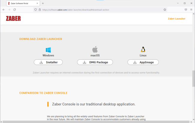
- Install Zaber Launcher software for the appropriate operating system: https://software.zaber.com/zaber-launcher/download#download-section
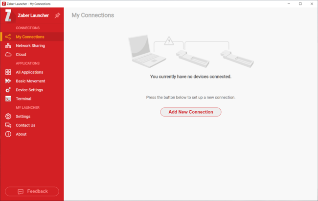
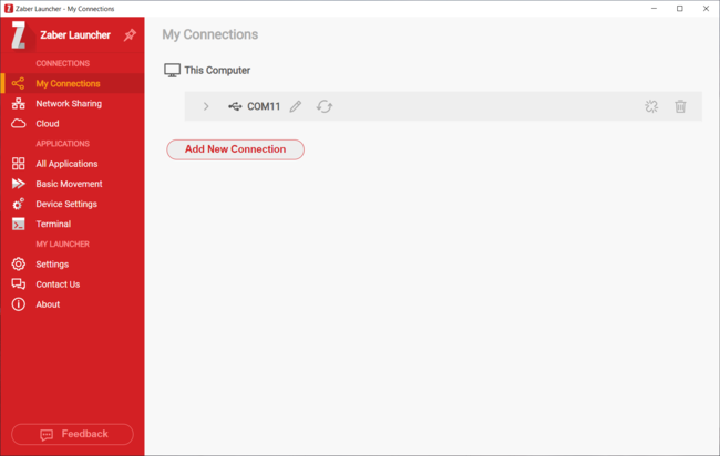
- Open Zaber Launcher.
- Click the “Add New Connection” button (or, use a previously configured connection for the device).
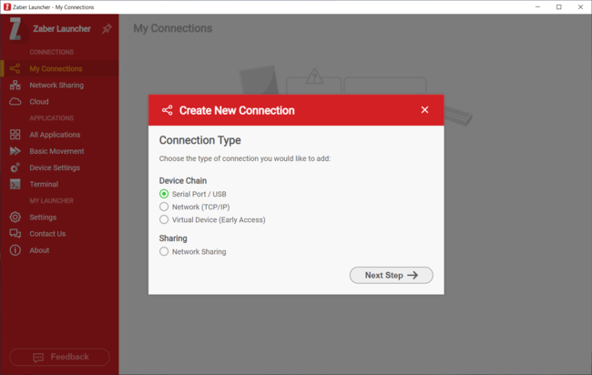
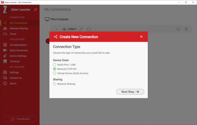
- Select the “Serial Port / USB” option and click the “Next Step” button.
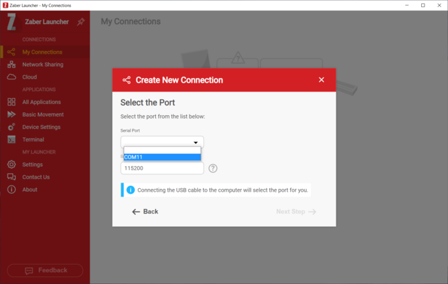
- Select the appropriate “Serial Port” from the drop-down list.
- Click “Next Step”, and then “Create Connection”.
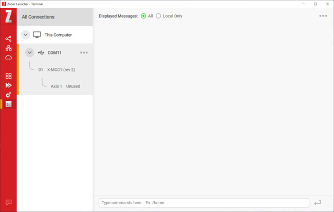
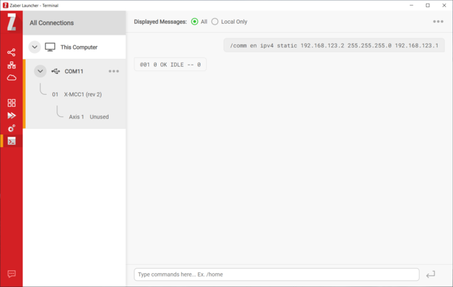
- Select “Terminal” from the sidebar.
- Select the appropriate connection from the “All Connections” list.
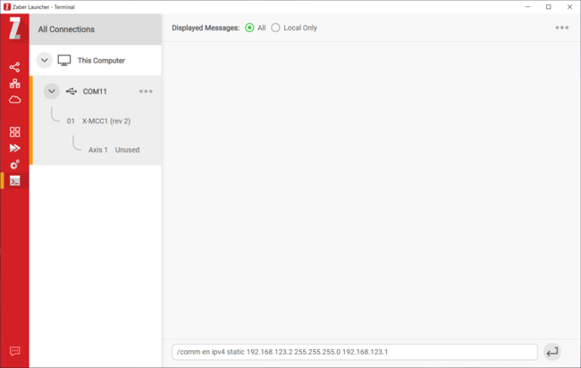
- Enter the “comm en ipv4 static” command to apply the network configuration (replace the sample values shown here with appropriate values for your network):
/comm en ipv4 static 192.168.123.2 255.255.255.0 192.168.123.1
- The Zaber device is now configured to use the provided network details.
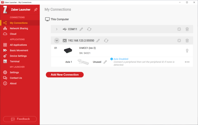
Connecting via Ethernet
- Connect the Zaber device to the network using an Ethernet cable.
- Open Zaber Launcher.
- Click the “Add New Connection” button.
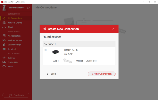
- Select the “Network (TCP/IP)” option and click the “Next Step” button.
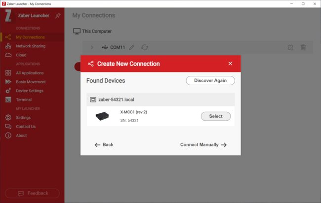
-
- If the Zaber device is detected automatically in the “Found Devices” listing, click the “Select” button.
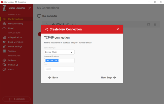
- Otherwise, click the “Connect Manually” button, then enter the device’s configured IPv4 address in the “Hostname/IP Address” field.
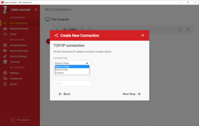
- In the “Connection Type” field, select “Device Chain” (for communicating with a device and daisy-chained devices) or “Device Only” (for communicating with the directly connected device only), then click the “Next Step” button.
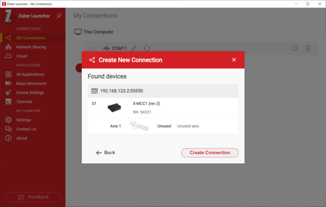
- Select the Zaber device from the "Found devices" list. Click the “Create Connection” button.
- The Zaber device is now listed in the “My Connections” list and is ready for use with Zaber Launcher.
Product Drawings
Specifications
| Specification | Value | Alternate Unit |
|---|---|---|
| AutoDetect | Yes | |
| Communication Interface | RS-232, USB 2.0, Ethernet (10/100 Mbit/s) | |
| Communication Protocol | Zaber ASCII (Default), Zaber Binary | |
| Data Cable Connection | Locking 4-pin M8, USB-B | |
| Power Supply | 24-48 VDC | |
| Power Plug | 5.0 mm screw terminal | |
| Maximum Current Draw | Motor and supply voltage dependent mA | |
| Controller Maximum Current Per Phase | 6 Arms | 10 A peak |
| Motor Connection | D-Sub 26 female | |
| Manual Control | Indexed knobs with push switches | |
| Limit Sensors per Axis | 3 | |
| Isolated Digital Input | 4 | |
| Isolated Digital Output | 4 | |
| Analog Input | 4 | |
| Analog Input Range | 0-10 V | |
| Analog Input Resolution | 1 mV | |
| Analog Output | 1 | |
| Analog Output Range | 0-10 V | |
| Analog Output Resolution | 2.5 mV | |
| Analog Output Impedance | 100 Ω | |
| External Regen Resistor | 5 Ω, 300 W | |
| E-Stop Input Range | 12-48 V | |
| 2D Primitives Supported | Lines, Arcs, Circles, and Helices | |
| Operating Temperature Range | 0 to 50 °C | |
| CE Compliant | Yes | |
| Vacuum Compatible | No |
Comparison
| Part Number | Axes of Motion | Encoder Output Axes | Encoder Output Type | Weight |
|---|---|---|---|---|
| X-MCC1 | 1 | 0 | None | 0.5 kg (1.102 lb) |
| X-MCC2 | 2 | 0 | None | 0.7 kg (1.543 lb) |
| X-MCC3 | 3 | 0 | None | 0.9 kg (1.984 lb) |
| X-MCC4 | 4 | 0 | None | 1.1 kg (2.425 lb) |
| X-MCC1-T7N1 | 1 | 1 | T7 - TTL Encoder Output From -E Peripherals | 0.5 kg (1.102 lb) |
| X-MCC2-T7N1 | 2 | 1 | T7 - TTL Encoder Output From -E Peripherals | 0.7 kg (1.543 lb) |
| X-MCC2-T7N2 | 2 | 2 | T7 - TTL Encoder Output From -E Peripherals | 0.7 kg (1.543 lb) |
| X-MCC3-T7N1 | 3 | 1 | T7 - TTL Encoder Output From -E Peripherals | 0.9 kg (1.984 lb) |
| X-MCC3-T7N2 | 3 | 2 | T7 - TTL Encoder Output From -E Peripherals | 0.9 kg (1.984 lb) |
| X-MCC3-T7N3 | 3 | 3 | T7 - TTL Encoder Output From -E Peripherals | 0.9 kg (1.984 lb) |
| X-MCC4-T7N1 | 4 | 1 | T7 - TTL Encoder Output From -E Peripherals | 1.1 kg (2.425 lb) |
| X-MCC4-T7N2 | 4 | 2 | T7 - TTL Encoder Output From -E Peripherals | 1.1 kg (2.425 lb) |
| X-MCC4-T7N3 | 4 | 3 | T7 - TTL Encoder Output From -E Peripherals | 1.1 kg (2.425 lb) |
| X-MCC4-T7N4 | 4 | 4 | T7 - TTL Encoder Output From -E Peripherals | 1.1 kg (2.425 lb) |
| X-MCC1-T8N1 | 1 | 1 | T8 - Interpolated RS422 Encoder Output From -AE Peripherals | 0.5 kg (1.102 lb) |
| X-MCC2-T8N1 | 2 | 1 | T8 - Interpolated RS422 Encoder Output From -AE Peripherals | 0.7 kg (1.543 lb) |
| X-MCC2-T8N2 | 2 | 2 | T8 - Interpolated RS422 Encoder Output From -AE Peripherals | 0.7 kg (1.543 lb) |
| X-MCC3-T8N1 | 3 | 1 | T8 - Interpolated RS422 Encoder Output From -AE Peripherals | 0.9 kg (1.984 lb) |
| X-MCC3-T8N2 | 3 | 2 | T8 - Interpolated RS422 Encoder Output From -AE Peripherals | 0.9 kg (1.984 lb) |
| X-MCC3-T8N3 | 3 | 3 | T8 - Interpolated RS422 Encoder Output From -AE Peripherals | 0.9 kg (1.984 lb) |
| X-MCC4-T8N1 | 4 | 1 | T8 - Interpolated RS422 Encoder Output From -AE Peripherals | 1.1 kg (2.425 lb) |
| X-MCC4-T8N2 | 4 | 2 | T8 - Interpolated RS422 Encoder Output From -AE Peripherals | 1.1 kg (2.425 lb) |
| X-MCC4-T8N3 | 4 | 3 | T8 - Interpolated RS422 Encoder Output From -AE Peripherals | 1.1 kg (2.425 lb) |
| X-MCC4-T8N4 | 4 | 4 | T8 - Interpolated RS422 Encoder Output From -AE Peripherals | 1.1 kg (2.425 lb) |
| X-MCC1-T15N1 | 1 | 1 | T15 - RS422 Encoder Output From -DE Peripherals | 0.5 kg (1.102 lb) |
| X-MCC2-T15N1 | 2 | 1 | T15 - RS422 Encoder Output From -DE Peripherals | 0.7 kg (1.543 lb) |
| X-MCC2-T15N2 | 2 | 2 | T15 - RS422 Encoder Output From -DE Peripherals | 0.7 kg (1.543 lb) |
| X-MCC3-T15N1 | 3 | 1 | T15 - RS422 Encoder Output From -DE Peripherals | 0.9 kg (1.984 lb) |
| X-MCC3-T15N2 | 3 | 2 | T15 - RS422 Encoder Output From -DE Peripherals | 0.9 kg (1.984 lb) |
| X-MCC3-T15N3 | 3 | 3 | T15 - RS422 Encoder Output From -DE Peripherals | 0.9 kg (1.984 lb) |
| X-MCC4-T15N1 | 4 | 1 | T15 - RS422 Encoder Output From -DE Peripherals | 1.1 kg (2.425 lb) |
| X-MCC4-T15N2 | 4 | 2 | T15 - RS422 Encoder Output From -DE Peripherals | 1.1 kg (2.425 lb) |
| X-MCC4-T15N3 | 4 | 3 | T15 - RS422 Encoder Output From -DE Peripherals | 1.1 kg (2.425 lb) |
| X-MCC4-T15N4 | 4 | 4 | T15 - RS422 Encoder Output From -DE Peripherals | 1.1 kg (2.425 lb) |
| X-MCC1-T16N1 | 1 | 1 | T16 - RS422 Encoder Output From -E Peripherals | 0.5 kg (1.102 lb) |
| X-MCC2-T16N1 | 2 | 1 | T16 - RS422 Encoder Output From -E Peripherals | 0.7 kg (1.543 lb) |
| X-MCC2-T16N2 | 2 | 2 | T16 - RS422 Encoder Output From -E Peripherals | 0.7 kg (1.543 lb) |
| X-MCC3-T16N1 | 3 | 1 | T16 - RS422 Encoder Output From -E Peripherals | 0.9 kg (1.984 lb) |
| X-MCC3-T16N2 | 3 | 2 | T16 - RS422 Encoder Output From -E Peripherals | 0.9 kg (1.984 lb) |
| X-MCC3-T16N3 | 3 | 3 | T16 - RS422 Encoder Output From -E Peripherals | 0.9 kg (1.984 lb) |
| X-MCC4-T16N1 | 4 | 1 | T16 - RS422 Encoder Output From -E Peripherals | 1.1 kg (2.425 lb) |
| X-MCC4-T16N2 | 4 | 2 | T16 - RS422 Encoder Output From -E Peripherals | 1.1 kg (2.425 lb) |
| X-MCC4-T16N3 | 4 | 3 | T16 - RS422 Encoder Output From -E Peripherals | 1.1 kg (2.425 lb) |
| X-MCC4-T16N4 | 4 | 4 | T16 - RS422 Encoder Output From -E Peripherals | 1.1 kg (2.425 lb) |
Product Change Notices
Click here to view the current product change notices and subscribe to future change notifications.
This product uses the FreeRTOS kernel. FreeRTOS is © 2026 Amazon.com, Inc. or its affiliates and is governed by the following license:
All rights reserved.
Permission is hereby granted, free of charge, to any person obtaining a copy of this software and associated documentation files (the "Software"), to deal in the Software without restriction, including without limitation the rights to use, copy, modify, merge, publish, distribute, sublicense, and/or sell copies of the Software, and to permit persons to whom the Software is furnished to do so, subject to the following conditions:
The above copyright notice and this permission notice shall be included in all copies or substantial portions of the Software.
THE SOFTWARE IS PROVIDED "AS IS", WITHOUT WARRANTY OF ANY KIND, EXPRESS OR IMPLIED, INCLUDING BUT NOT LIMITED TO THE WARRANTIES OF MERCHANTABILITY, FITNESS FOR A PARTICULAR PURPOSE AND NONINFRINGEMENT.
IN NO EVENT SHALL THE AUTHORS OR COPYRIGHT HOLDERS BE LIABLE FOR ANY CLAIM, DAMAGES OR OTHER LIABILITY, WHETHER IN AN ACTION OF CONTRACT, TORT OR OTHERWISE, ARISING FROM, OUT OF OR IN CONNECTION WITH THE SOFTWARE OR THE USE OR OTHER DEALINGS IN THE SOFTWARE.
This product uses the LZ4 compression library. LZ4 is © 2011–2016 Yann Collet and is governed by the following license:
All rights reserved.
Redistribution and use in source and binary forms, with or without modification, are permitted provided that the following conditions are met:
- Redistributions of source code must retain the above copyright notice, this list of conditions and the following disclaimer.
- Redistributions in binary form must reproduce the above copyright notice, this list of conditions and the following disclaimer in the documentation and/or other materials provided with the distribution.
THIS SOFTWARE IS PROVIDED BY THE COPYRIGHT HOLDERS AND CONTRIBUTORS "AS IS" AND ANY EXPRESS OR IMPLIED WARRANTIES, INCLUDING, BUT NOT LIMITED TO, THE IMPLIED WARRANTIES OF MERCHANTABILITY AND FITNESS FOR A PARTICULAR PURPOSE ARE DISCLAIMED. IN NO EVENT SHALL THE COPYRIGHT HOLDER OR CONTRIBUTORS BE LIABLE FOR ANY DIRECT, INDIRECT, INCIDENTAL, SPECIAL, EXEMPLARY, OR CONSEQUENTIAL DAMAGES (INCLUDING, BUT NOT LIMITED TO, PROCUREMENT OF SUBSTITUTE GOODS OR SERVICES; LOSS OF USE, DATA, OR PROFITS; OR BUSINESS INTERRUPTION) HOWEVER CAUSED AND ON ANY THEORY OF LIABILITY, WHETHER IN CONTRACT, STRICT LIABILITY, OR TORT (INCLUDING NEGLIGENCE OR OTHERWISE) ARISING IN ANY WAY OUT OF THE USE OF THIS SOFTWARE, EVEN IF ADVISED OF THE POSSIBILITY OF SUCH DAMAGE.
This product uses the lwIP TCP/IP stack. lwIP is © 2001, 2002 Swedish Institute of Computer Science and is governed by the following license:
All rights reserved.
Redistribution and use in source and binary forms, with or without modification, are permitted provided that the following conditions are met:
- Redistributions of source code must retain the above copyright notice, this list of conditions and the following disclaimer.
- Redistributions in binary form must reproduce the above copyright notice, this list of conditions and the following disclaimer in the documentation and/or other materials provided with the distribution.
- The name of the author may not be used to endorse or promote products derived from this software without specific prior written permission.
THIS SOFTWARE IS PROVIDED BY THE AUTHOR "AS IS" AND ANY EXPRESS OR IMPLIED WARRANTIES, INCLUDING, BUT NOT LIMITED TO, THE IMPLIED WARRANTIES OF MERCHANTABILITY AND FITNESS FOR A PARTICULAR PURPOSE ARE DISCLAIMED. IN NO EVENT SHALL THE AUTHOR BE LIABLE FOR ANY DIRECT, INDIRECT, INCIDENTAL, SPECIAL, EXEMPLARY, OR CONSEQUENTIAL DAMAGES (INCLUDING, BUT NOT LIMITED TO, PROCUREMENT OF SUBSTITUTE GOODS OR SERVICES; LOSS OF USE, DATA, OR PROFITS; OR BUSINESS INTERRUPTION) HOWEVER CAUSED AND ON ANY THEORY OF LIABILITY, WHETHER IN CONTRACT, STRICT LIABILITY, OR TORT (INCLUDING NEGLIGENCE OR OTHERWISE) ARISING IN ANY WAY OUT OF THE USE OF THIS SOFTWARE, EVEN IF ADVISED OF THE POSSIBILITY OF SUCH DAMAGE.