Automating Laser Interferometer Alignment for Calibration
By Ryan Cifra, Marketing Team
Published on Jun. 30, 2026
While many manufacturers use laser interferometers to calibrate precision motion systems, the beam alignment portion often remains a manual process. Operators repeatedly adjust pitch and yaw using mechanical thumbscrews while monitoring the return signal, making alignment time-consuming, operator-dependent, and difficult to scale. This case study describes how Zaber automates the alignment portion of our linear stage calibration process using real-time feedback from a position sensitive detector (PSD). By combining standard modular motion components with an automated alignment algorithm, we replaced a repetitive manual workflow with a simple process that increases throughput while remaining cost-effective.
The Challenge: Scaling the Manual Alignment Process
During calibration, our linear stages must move through their full length of travel to map errors. To ensure we capture accurate data, the laser beam from the SIOS interferometer must first go through a precise alignment process to maintain a readable signal across the entire length of the device. Previously, this required a highly active manual process that took up to 10 minutes per stage and required the operator to:
- Manually position the interferometer until a return signal is detected.
- Adjust the interferometer's angular orientation (pitch and yaw) using mechanical thumbscrews to align the beam.
- Adjust the interferometer’s horizontal and vertical positions using mechanical thumbscrews to counteract the offset created by angular adjustments.
- Move the stage through its travel, stopping periodically to correct alignment as the reflected beam drifts off-center.
While this approach achieved the required accuracy, it tied up skilled engineers with repetitive manual tasks, introduced operator-to-operator variability, and limited manufacturing throughput.
The Goal: High-Throughput Automated Alignment
To fulfill our commitment of lead times under 1 week, we needed a faster and more repeatable alignment workflow within our calibration station that could:
- Support alignment of multiple, differently sized products on the same station with a single interferometer vs. buying several.
- Automate pitch and yaw adjustments to perform the fine angular corrections required for beam alignment.
- Coordinate the motion of the device with the interferometer during the alignment process without operator intervention.
The Solution: An Automated Metrology Station
 Figure 1: Automated Calibration Station made with an SIOS interferometer and off-the-shelf motion components.
To achieve these goals, we built an automated motion system into our calibration station that can accommodate up to three linear stages at once. This setup replaces manual adjustments of a single interferometer with automated sequences using off-the-shelf motion hardware:
- Motorized thumbscrew adjustments: The manual thumbscrews to adjust pitch and yaw were removed and replaced with linear actuators. Instead of an operator adjusting by hand, the software drives these actuators to physically tilt and turn the interferometer.
- Automated horizontal and vertical positioning: A dual-axis motorized system moves the interferometer to find multiple devices in a single run. It handles this long-range motion while maintaining the precision needed for coarse alignment and counteracting beam offsets from angular adjustments.
The Result: Increased Walk-Away Time and Throughput
Operators can now mount up to three stages at once, click “Run,” and walk away. This upgrade delivers two major benefits:
- Saves up to 30 minutes per batch: Eliminating the 10 minutes of manual alignment previously required for each stage reclaims valuable production time.
- Frees up skilled labor: Operators can shift their focus to higher-value tasks while the system runs autonomously.
System Design: How to Build an Interferometer Positioning System (IPS)
Coarse Positioning: Using Motion Stages for Alignment
 Figure 2: Interferometer Positioning System (IPS) to control horizontal and vertical positioning of the interferometer.
The IPS is built using two Zaber X-LRQ-E linear stages mounted in an XZ configuration selected primarily for their high stiffness. When supporting a relatively heavy optical payload, structural deflection or vibration can compromise measurement repeatability, making stiffness an important design consideration. The two linear stages provide:
- 600 mm x 150 mm of travel, enabling the interferometer to access multiple positions across the workspace.
- 2.5 µm repeatability for horizontal and vertical axes to ensure the system maintains consistent mechanical behaviour.
- 90 µm horizontal accuracy and 45 µm vertical accuracy* that provides a reliable operational window for coarse positioning.
Learn how we define accuracy.
The IPS is based on a standard configuration generated using Zaber's Online XY Stage Configurator, with several application-specific modifications:
- Vertical axis: A fine-pitch lead screw was selected due to its non-backdriving capabilities, while an inline motor configuration better aligned the center of mass. This reduces off-axis moments, secures the payload when the device is powered down and improves alignment stability during motion.
- Horizontal axis: A medium-pitch lead screw provides a balance between positioning performance and travel speed. Because this axis is used for coarse positioning rather than measurement, faster motion improves throughput without sacrificing system performance. A parallel motor configuration is selected here to reduce the overall footprint of the platform.
Together, these design choices create an efficient and stable positioning system capable of supporting automated calibration across multiple devices of various geometries on a table
Fine Alignment: Automating Thumbscrew Adjustments
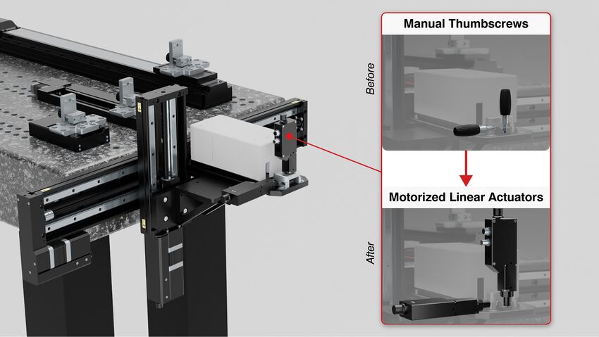 Figure 3:Close up comparison of manual thumbscrews to the new motorized linear actuators on the laser interferometer
To automate the fine pitch and yaw corrections based on real-time PSD feedback, we replaced the interferometer's manual adjustment knobs with two compact Zaber X-NA08A25-S linear actuators with integrated controllers.
Automating pitch and yaw adjustment requires a balance of force and precision. The actuators must generate enough thrust to reliably tilt the interferometer while also providing the fine positioning resolution needed for small angular corrections.
We selected two Zaber X-NA08A25-S linear actuators with integrated controllers, providing:
- 5.6 N peak thrust to produce pitch and yaw adjustments.
- 2.5 µm repeatability and 0.047 µm microstep size* to support consistent and precise automated positioning
Learn how we define microstep size.
Manual Control Joystick for Setup and Troubleshooting
Although the system is designed to operate autonomously during alignment, manual control remains valuable during setup, maintenance, and troubleshooting. A handheld joystick provides direct control of the IPS and motorized pitch and yaw actuators, allowing operators to quickly reposition the interferometer or make manual adjustments when needed. This simplifies initial system setup and enables engineers to verify or debug the alignment process without modifying software.
A bill of materials is available in the appendix below. Zaber’s plug-and-play modularity ensures a clean, simplified setup. All motion hardware comes with a built-in controller, allowing the devices to be daisy-chained to one another. This simplifies the setup by only needing one cable for both power and data between devices. This shared communication allows a single Python script to control the system via Zaber’s open-source API.
Software: Automating a Manual Metrology Process
Automating the mechanical components is only part of the solution. The IPS and motorized actuators must also work together to reliably locate and maintain laser alignment across different products and operating conditions. To achieve this, the system was programmed in Python using the open-source Zaber Motion Library API.
The workflow is divided into two stages: coarse positioning of the interferometer to roughly locate the reflected beam, followed by closed-loop beam alignment using feedback from the position sensitive detector (PSD).
Automated Device Detection
Figure 4: Video of the IPS moving the interferometer to find the first device
Before alignment begins, the interferometer is moved to a predetermined vertical height (Z) corresponding to the retroreflector mounted on the first device under test. Because the height of each product is known in advance, this provides a repeatable starting point for the search process.
The IPS then scans across the workspace while the position sensitive detector (PSD) monitors the returning laser beam in real time. When a valid reflection is detected, the scan stops automatically and the interferometer position is recorded.
Centering the laser upon detection, the returning laser beam typically lands on the outer edge of the PSD’s active area. Before fine pitch and yaw adjustments begin, the IPS performs a centering operation to position the return beam on the PSD until an optimal signal is reached.
To improve reliability, the software:
- Waits briefly after stopping to allow the PSD output to settle.
- Confirms that the PSD reading is stable before proceeding.
- Ignores stray reflections and continues scanning until the retroreflector is found.
Using a PSD for Beam Alignment Over Long Travel
Figure 5: Video of the automated alignment sequence keeping the SIOS interferometer aligned across the stage’s full travel
Once the PSD readings are stable, the system begins fine alignment over the full travel of the stage under test.
Using feedback from the PSD, the software iteratively adjusts the interferometer's pitch and yaw until the beam remains centered and the alignment error falls within the specified tolerances. Rather than optimizing in a single step, the system continuously measures beam position and applies corrections across multiple points along the stage travel. This iterative approach directly compensates for mechanical variation, ensuring repeatable, unattended alignment across multiple devices.
Design Considerations for High Precision Metrology Systems
- Reduce Thermal Drift: For thermally sensitive setups, select a finer pitch Z-axis lead screw to mitigate backdriving force. This allows the motor current to be lowered or even dropped to zero entirely when static, reducing heat generation and minimizing thermal expansion that can introduce small shifts in measurement accuracy.
- Implement Settling Delays: Include a brief delay or sensor verification check in the code after each motion command. This allows structural vibrations to fully dampen before the system takes a measurement, ensuring maximum data integrity.
Customization possibilities
- Dual-Carriage Linear Stages: Greatly improve pitch, roll, and yaw stiffness across long travel ranges.
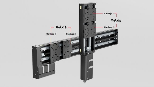 Figure 6: Zaber XZ stage featuring the custom dual-carriage option
- Dual Y-Axis LRQ Configuration: Centers the interferometer mass between stages to significantly decrease roll error by increasing overall system stiffness.
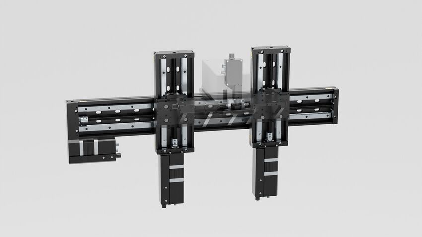 Figure 7: Custom Zaber stage layout with dual vertical axes, allowing the interferometer to be centrally mounted to share the weight and maximize stability.
If your application outgrows standard hardware, Zaber’s Custom Engineering Team is ready to help. We can modify standard products or build custom multi-axis systems tailored to your space and precision requirements.
Conclusion
The automated system reduces operator intervention, increases throughput, and enables a single calibration station to support multiple products. Although this project was developed for production calibration, the same architecture can be applied to many applications requiring automated alignment, such as laser tuning, fibre alignment, or laser diode manufacturing. By using standard hardware components with an open-source API, engineers can build flexible, production-ready systems that deliver the performance of turnkey solutions at a fraction of the cost.
Appendix: Bill of Materials
XZ System that the calibration setup is based off of: XY LRQ
| Component | Purpose | Cost (USD) |
|---|---|---|
| X-LRQ 600 mm linear stage | Horizontal interferometer positioning | $5,159 |
| X-LRQ 150 mm linear stage | Vertical interferometer positioning | $3,510 |
| X-NA08A25-S actuator | Pitch adjustment | $1,212 |
| X-NA08A25-S actuator | Yaw adjustment | $1,212 |
| Interferometer mounting plate | Mounts the interferometer to XZ stage top | ~$300 |
| Zaber X-Joy Controller | Manual control | $895 |
| Power & Cables | Power and data transfer | $467 |
| Total | ~$12,755 |
Table 1: Bill of Materials