
NMB-E Series User's Manual
Brushless DC Servo Motors With Optional Brakes
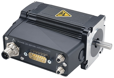
Table of Contents
Table of Contents
Disclaimer
Zaber’s products are not intended for use in any critical medical, aviation, or military applications or situations where a product's use or failure could cause personal injury, death, or damage to property. Zaber disclaims any warranty of fitness for a particular purpose. The user of this product agrees to Zaber's general terms and conditions of sale.
Precautions
Zaber's autodetect peripheral axes are designed to be used effortlessly with Zaber's line of autodetect controllers. The NMB-E includes onboard memory that allows Zaber's controllers to autodetect the model and set reasonable parameters. See the Protocol Manual for more information on how to modify the settings. Damage to the axis may result if the settings are not correct. To use your Zaber peripheral with a third-party controller, review the motor, sensor, and encoder specifications and pin-outs carefully.
 Cross-wiring Risk: This product has two connections to the Zaber controller: an M12 connector for the motor phase wires and a D-Sub connector (DB15 or DB26) for sensor signals. When connecting two or more peripherals which have the M12 connector, care must be taken to ensure that the two cables are connected to the same axis on the controller. Zaber recommends using color-coding to provide a visual check of wiring correctness.
 Caution: The motor in this device can exceed 60° C during normal operation and become hot enough to cause burns. Take precautions to prevent contact with the motor.
Caution - Servo Device: The NMB-E is a servo device, meaning that its performance is dependent on proper tuning of the servo parameters for the given load. The use of incorrect servo parameters may reduce the device’s performance in operation. Incorrect tuning may result in unstable operation, which can cause unexpected rapid motion of the device, leading to reduced device lifetime and/or user injury. Another effect of incorrect tuning parameters can be trajectory overshoot or long settling times. When the operating load on the device is changed, the tuning parameters should be updated to match. For details see the servo tuning guidelines.
No Motion During Power-up: The BLDC motor must be stationary during power up. This is necessary for the correct function of the absolute shaft encoder, which transmits the shaft position on startup. Motion during this transmission time can lead to incorrect position information being received by the controller. If the system design is such that motion is unavoidable due to external influences, consider using a product variant that includes a brake.
Caution for Startup: The controller should always be powered down before disconnecting or connecting your NMB-E peripheral. Damage to the peripheral and/or controller can occur when connecting or disconnecting while powered.
Dynamic Stops: The power-off brake is intended to prevent damage and maintain the position of a static load in the event of a power loss. Precautions should be taken to avoid dynamic braking when possible, as this may reduce brake lifetime.
Mounting and Maintenance Hazard! For operator safety, the NMB-E should always be un-powered during all cleaning, maintenance, and stage or load mounting operations. A powered stage could exert high forces and move at high speeds unexpectedly.
Power Supply Requirements: The BLDC motor can draw high currents. If the BLDC motor is equipped with the high-current motor connector, each motor must be directly supplied by a dedicated power supply suitable for the motor's current specification.
 Important: The NMB-E motor should be homed immediately upon power-up.
Space Constraints: Plastic covers on the power-off brake extend outside the motor form factor and may be removed when space is limited, but should remain attached otherwise.
Dust Generation: Brake pads may generate small amounts of dust particulate over their lifetime of use.
Noise Emissions
The A-weighted emission sound pressure level (SPL) of this device does not exceed 70 dB(A) during intended use.
Conventions used throughout this document
- Fixed width type indicates communication to and from a device. The ↵ symbol indicates a carriage return, which can be achieved by pressing enter when using a terminal program.
Device Overview
AutoDetect
Your NMB-E peripheral is equipped with AutoDetect, a feature that allows a Zaber controller to automatically configure its settings for the peripheral when it is connected.
Important: The controller should always be powered down before disconnecting or connecting your NMB-E peripheral.
To connect the peripheral to a controller:
- Power off the controller.
- Connect the NMB-E peripheral.
- Power on the controller.
- The controller will activate the peripheral shortly after it is powered on.
Controller Compatibility: X-MCC (revision 2+) with firmware (FW 7.61+) is required for the operation of devices with a BLDC motor. See the Zaber controller user manual for more details on peripheral activation and control.
Connectors
Recommended controller(s) for your NMB-E peripheral are provided in the product specifications. Zaber's controllers and peripherals are designed for ease of use when used together. Optimal settings for each peripheral are automatically detected by Zaber's controllers when the device is connected.
For reference, the pinout for the peripheral cable connectors is shown below:
6 Amp Motor Interface
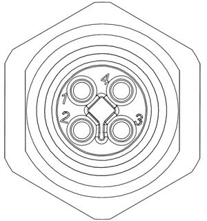
Male T-Coded M12 Connector |
Pin # | BLDC Motor Connection |
|---|---|---|
| 1 | Motor V | |
| 2 | Motor U | |
| 3 | N.C. | |
| 4 | Motor W |
NOTE: If using this connector, the four motor pins on the D-sub connector must not be used.
Pinout for D-sub 15 Connectors (peripherals)
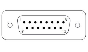
Male DB15 Connector |
Pin # | Function |
|---|---|---|
| 1 | +5V for Limits & Encoder | |
| 2 | AutoDetect Data | |
| 3 | Encoder Power Enable | |
| 4 | Away Sensor | |
| 5 | Home Sensor | |
| 6 | Ground | |
| 7 | N/C | |
| 8 | N/C | |
| 9 | AutoDetect Clock | |
| 10 | Encoder A | |
| 11 | Encoder B | |
| 12 | Encoder Index | |
| 13 | Ground | |
| 14 | N/C | |
| 15 | N/C |
Pinout for D-sub 26 Connectors (peripherals) for Brake-Equipped Products
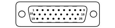
Male High Density D-sub26 Connector |
Pin | Description | Pin | Description |
|---|---|---|---|---|
| 1 | AutoDetect Clock | 14 | Single-ended Encoder Index | |
| 2 | AutoDetect Data | 15 | +5V | |
| 3 | Encoder Power Enable | 16 | Ground | |
| 4 | Away Limit Sensor | 17 | Brake- | |
| 5 | Home Limit Sensor | 18 | N.C. | |
| 6 | N.C. | 19 | N.C. | |
| 7 | Ground | 20 | N.C. | |
| 8 | N.C. | 21 | N.C. | |
| 9 | N.C. | 22 | Single-ended Encoder A | |
| 10 | N.C. | 23 | Single-ended Encoder B | |
| 11 | N.C. | 24 | N.C. | |
| 12 | N.C. | 25 | Brake+ | |
| 13 | N.C. | 26 | N.C. |
NOTE: All hall sensor signals (for limits or motor phase) are open collector and require a pull-up on the controller.
NOTE: All single-ended encoder inputs are non-isolated 5V TTL lines.
External Hall Sensor
-
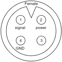
Device Connector
-
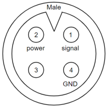
Sensor Connector
| Pin | Description |
|---|---|
| 1 | Signal |
| 2 | +5V |
| 3 | Reserved |
| 4 | Ground |
NOTE: The signal is pulled up to the internal supply rail and is designed to be pulled low by an open collector.
NOTE: Sensor inputs are non-isolated 5V TTL lines.
Alternate Controllers
The NMB-E motor has a built-in absolute shaft encoder. Due to the specific way this encoder reports its initial position and error information, Zaber does not recommend using an alternate controller with this product. Improper use can result in control loop instability and unintended motion at maximum device power, potentially causing harm to operators or damage to the system.
Power Supply Requirements
The NMB-E motor can draw high currents. When used with Zaber’s MCC controllers, each NMB-E motor must have a dedicated high-current power supply. Zaber strongly recommends using Zaber’s PS15S-48V65 power supply, or a dedicated power supply with sufficient current capacity to power the NMB-E.
Motors & Encoders
For motor and encoder information see the NMB-E product page
Absolute Shaft Encoder
The NMB-E motor is equipped with a high-resolution absolute shaft encoder. This encoder knows its position within one mechanical rotation of the motor shaft, and it provides this information to the controller when the encoder is initialized. This means that the motor can immediately be driven in a servo controlled mode.
The positioner still needs to be provided with a reference position by either homing or using the set pos (T:60) command. This is necessary because the encoder does not track multiple rotations of the motor shaft.
Limit Sensors
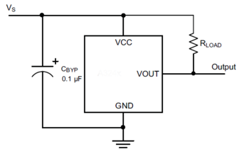
Hall effect sensors are used in the NMB-E as home and away sensors. The Hall sensors used are part number A1120LLHLT-T made by Allegro. Click here for data sheet. Your controller should be configured so the axis stops almost immediately (quick deceleration) when the sensors are triggered.
- PCB wire colour code:
- 5 Vdc input - red
- Home signal - yellow
- Away signal - white
- Ground - black
The Hall sensor has an open-collector output. The default output is high impedance when the Hall sensor is not active. When the sensor detects a magnet, the Hall sensor pulls the output low to ground.
Power-off Brake
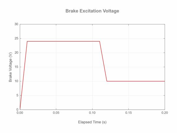
It is necessary to follow the recommended values for excitation and hold voltages:
- The initial excitation voltage of 24 V should be applied for at least 100 ms to ensure the power-off brake is opened.
- A hold voltage of 10 V can then be applied to reduce excess heating of the brake.
- When open, the brake will consume ~2 watts to remain open.
Brake Settings: The brake must be correctly configured in order to operate correctly. In Zaber’s controllers, there are multiple settings that affect correct operation. The default settings for the NMB-E product may need to be modified for some applications. When modifying these settings, be sure to follow the guidance in the Protocol Manual.
Installation
Replacing Stepper Motor Products
If an NMB-E motor is used to replace an NMS motor (ex. Replacing an NMS23 with an NMB23), the system design may need to be updated to account for the additional high-power cable used by the NMB-E motor. In addition to the number of cables, the system cable management may also need to be updated due to the increase in minimum bend radius of the MC12 cable compared to the MC10T3 cable.
Additionally, the NMB-E motor is a servo device and will have different trajectory following behaviour compared to a stepper motor. See the Servo Tuning section for more information. Servo control also means that the NMB-E motor will respond differently to a stall condition than a stepper motor - the BLDC will continue to apply maximum torque until the stall condition timeout is reached. Unlike a stepper motor, the BLDC does not normally make audible noise when stalling.
The typical operating acoustic behaviour of the BLDC motor is also different compared to steppers. In most cases, the BLDC will run more quietly than a stepper motor.
The default homing behavior of the NMB-E motor is different from an NMS-E stepper motor. The encoder present in the NMB-E assembly provides an index mark once per revolution, which is used as the default homing source for the NMB-E. An HS02 hall sensor is provided with the NMB-E motor for use in situations where:
- The motor is moving less than one full rotation.
- The motor is used to drive a system via a transmission.
See limit.home.source for more information on changing the homing source for the NMB-E.
Setting the Maximum Travel Limit
With default settings, the motor controller will be unaware of any physical travel limits and will hit the hard limits if commanded to move beyond them. The minimum device travel can be set using the limit.min setting, and the maximum device travel can be set using the limit.max setting. These settings can be modified using Zaber Launcher.
The values of limit.min and limit.max can be set to a known value based on a mechanical analysis of the system. Alternatively, the motor can be mounted in the system and the limit can be determined experimentally by slowly moving toward the ends of travel. The commands tools gotolimit and tools gotolimit hardstop can help automate this process.
If the motor is used in an application that requires continuous rotary motion, the settings limit.cycle.dist and limit.cycle.mode must be set to appropriate values.
Setting Direction and Homing Source
With default settings, the motor is configured to rotate in a clockwise direction when looking toward the shaft.
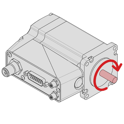
The motor is also configured to use the index signal from the integrated encoder as the homing sensor. The index signal is a single-count-wide pulse that occurs once per revolution. Using the index signal from the encoder has the advantage that no further sensor installation is necessary. However, some applications will require a hall sensor as the homing source - for example when the motor needs to have an absolute reference beyond one mechanical revolution.
To modify the direction of travel or the homing source for the motor, please use the Setup Application within Zaber Launcher to help configure the NMB-E. While the homing source can be modified manually by changing appropriate settings, the only recommended way to change the direction of travel is to use the Setup Application.
Physical Installation
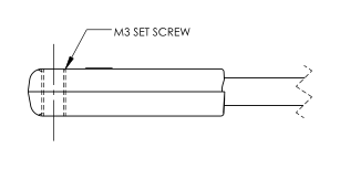
The provided Hall Effect limit sensors are compatible with a T-slot (see dimensions below). To install a sensor, slide it down the T-slot from the slot's end to the desired position and tighten the M3 set screw until sensor is just secure. Over-tightening may cause threads to strip in the sensor. A small boss on the top side of the sensor indicates the approximate centre of the sensing area on the underside. If possible, nest the cable within the slot to avoid catching or pulling the cable.

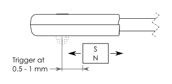
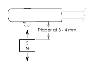
To mount the provided magnet, use a strong adhesive to fix the magnet in a position that allows it to trigger the sensor (see below). Ensure the south pole (black side) of the magnet faces the sensor. The Hall Effect sensor only triggers on a south pole with a magnetic field intensity of approximately 35 G or more. Use a stronger magnet to trigger the sensor from a great distance. The triggering distance will vary depending upon the magnet's strength, the direction from which it approaches the sensor, its orientation relative to the sensor, and surrounding magnetic material. Standard mounting configurations and triggering distances are shown below.
Also see Home or Away Sensor Installation Sheet.
Before operating the motor, ensure the NMB-E with brake is secured to its mating plate or device. For NMB-E brake devices, the four through-housing bolts shown must be securely fastened to prevent brake and housing rotation.

NMx23 Brake Cover Removal
The power-off brake is intended to operate with the attached brake covers. If form factor is an issue, the brake covers may be carefully removed as they protrude by up to 0.8 mm from the housing. Gently slide a screwdriver into the slot, and push the cover away from the shaft until it clears the edge of the opening.

Servo Tuning
This peripheral is a closed-loop positioning servo system. It continuously monitors and corrects its position via the absolute shaft encoder. As with any servo system, the behaviour is dependent on the controller tuning. The NMB-E, when paired with a compatible Zaber controller, such as an X-MCC series Universal Motor Controller, will be appropriately tuned out of the box with settings that are optimized for regular use under a light load. However, as with any closed-loop feedback system, the device performance is load-dependent, and conditions significantly outside of the intended operating range have the potential for reduced performance or instability. Thus, if operation with large or unconventional dynamic loads is desired, or if the application demands specific performance characteristics, it may be necessary to tune the servo parameters. This may be conveniently done by using Zaber Launcher's Servo Tuner App, or Zaber Motion Library's ServoTuner API. Additional settings that control the closed-loop behaviour of the product are described in the Zaber ASCII Protocol Manual. It is important to ensure that the chosen servo tuning parameters provide sufficient stability margin for the system that is being driven.
Tip: Because servo devices continuously monitor and correct position, it is necessary to specify how accurate and stable the final position must be at the end of the movement. Criteria required for the controller to report IDLE status after movement are specified using the cloop.settle.tolerance and cloop.settle.period settings. For applications requiring utmost precision, you may want to specify a smaller tolerance and longer period. Note that there is an inverse relationship between the value of cloop.settle.tolerance and real-life observed settling time, and the controller may never report IDLE status if the tolerance is too small.
The following diagram illustrates some of the possible issues with trajectory-following performance due to non-optimal servo tuning parameters. When the servo parameters are well tuned, the system will follow the planned trajectory (red line) with minimum deviation, as long as the chosen trajectory is achievable. For the poorly chosen servo parameters in the example below, there is significant lag and oscillation compared to the planned trajectory.
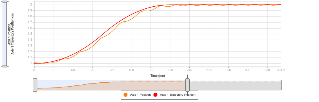
Tip: The position servo controller in Zaber products tracks a pre-planned motion trajectory. For this reason, it is sometimes necessary to modify the trajectory planning settings such as accel or maxspeed as well as the servo tuning parameters in order to obtain optimal positioning performance.
Trajectory Control and Behaviour
This section describes the behaviour of the axis trajectory when a movement command is issued.
Software Position Limits
The travel range of the axis is limited by the Minimum Position and Maximum Position settings. The factory settings for the axis are configured to match the physical travel range. If a customized range is desired, it can be changed by configuring the limit.min and limit.max settings to appropriate values. For the Current Position, query pos.
- Minimum Position
- When the Current Position is less than the Minimum Position value, the axis cannot move in the negative direction.
- Maximum Position
- When the Current Position is greater than the Maximum Position value, the axis cannot move in the positive direction.
Movement Speed
The movement speed of the axis depends on axis status and various speed settings. If the axis has not been initialized by the home command or by moving towards the home end of the axis, movement speed will be constrained to fail-safe values. The home status of the axis can be determined by reading the limit.home.triggered setting.
Movement speed of the axis is specified below:
- move vel
- The axis will move at the specified speed regardless of home status.
- Knob movement in Velocity Mode
- The axis will move at the specified speed regardless of home status.
- The speed is specified by the knob.speedprofile and knob.maxspeed settings.
- Other movement commands - when the axis has not been homed
- The axis will move at the slower of the maxspeed and limit.approach.maxspeed settings.
- Other movement commands - when the axis has been homed
- The axis will move at the speed specified by the maxspeed setting.
Power-Off Brake Control
Brake Settings: The brake must be correctly configured in order to operate correctly. In Zaber’s controllers, there are multiple settings that affect correct operation. The default settings for the NMB-E product may need to be modified for some applications. When modifying these settings, be sure to follow the guidance in the Protocol Manual.
Described below are the recommended procedures for operating a brake-equipped device:
- Dynamic Brake Engagement - For Position Holding After Faults
- The power-off brake opens by default when the system is powered up. The brake will close if the device stalls, is displaced while stationary, the driver is disabled, or the power is interrupted. Repeated dynamic stopping may reduce the lifetime of the brake. We strongly recommend avoiding dynamic braking when possible.
- Stationary Brake Engagement - For Position Holding
- The power-off brake opens by default when the system is powered up. To change the brake state, use brake.mode.
- The order of operations to set a retaining position should follow:
- Open the brake by setting brake.mode to 1.
- Allow 100 ms for the brake to open.
- Move the positioner.
- Close the brake by setting brake.mode to 0.
- Allow 100 ms for the brake to close.
- If accuracy is required, the driver.current.hold↵ (T:39) should remain on to prevent slight shifts in the device position.
- Stationary Brake Engagement - For Reducing Motor Heat
- The power-off brake opens by default when the system is powered up. To change the brake state, use brake.mode. To reduce heat generated in the motor, use the driver disable command in between moves.
- The order of operations to maintain a vertical position, and disabling the driver to reduce heat, should follow:
- Set the hold current to the appropriate value based on load (see defaults on website).
- Move the positioner to the intended location.
- Send the driver disable command. The brake will automatically close.
- When ready to move again, send the driver enable command. The brake will open.
- Move the positioner as normal
- Turning off the hold current will cause a small displacement of the positioner.
- Manual Device Movement
- Manual Device movement requires disabling the encoder displacement detection to prevent engagement of the power-off brake. The order of operations for manual movement should follow:
- Remove any load from the positioner.
- Disable closed-loop control by setting cloop.enable to 0 .
- Set the hold current to 0.
- Move the positioner manually by hand. For screw driven linear devices, turning the lead screw can assist in achieving smaller increments during manual movement.
Warranty and Repair
For Zaber's policies on warranty and repair, please refer to the Ordering Policies.
Standard products
Standard products are any part numbers that do not contain the suffix ENG followed by a 4 digit number. Most, but not all, standard products are listed for sale on our website. All standard Zaber products are backed by a one-month satisfaction guarantee. If you are not satisfied with your purchase, we will refund your payment minus any shipping charges. Goods must be in brand new saleable condition with no marks. Zaber products are guaranteed for one year. During this period Zaber will repair any products with faults due to manufacturing defects, free of charge.
Custom products
Custom products are any part numbers containing the suffix ENG followed by a 4 digit number. Each of these products has been designed for a custom application for a particular customer. Custom products are guaranteed for one year, unless explicitly stated otherwise. During this period Zaber will repair any products with faults due to manufacturing defects, free of charge.
How to return products
Customers with devices in need of return or repair should contact Zaber to obtain an RMA form which must be filled out and sent back to us to receive an RMA number. The RMA form contains instructions for packing and returning the device. The specified RMA number must be included on the shipment to ensure timely processing.
Email Updates
If you would like to receive our periodic email newsletter including product updates and promotions.
Contact Information
Contact Zaber Technologies Inc by any of the following methods:
| Phone | 1-604-569-3780 (direct) 1-888-276-8033 (toll free in North America) |
|---|---|
| Fax | 1-604-648-8033 |
| #2 - 605 West Kent Ave. N., Vancouver, British Columbia, Canada, V6P 6T7 | |
| Web | www.zaber.com |
| Please visit our website for up to date email contact information. |
The original instructions for this product are available at https://www.zaber.com/manuals/NMB-E.
Appendix A: Default Settings
Please see the Zaber Support Page for default settings for this device.
Product Drawings
Specifications
| Specification | Value | Alternate Unit |
|---|---|---|
| Built-in Controller | No | |
| Recommended Controller | MCC (48 V) Recommended | |
| AutoDetect | Yes | |
| Repeatability | < 0.02° | < 0.349 mrad |
| Maximum Torque | 1.7 N⋅m | 1.255 lb⋅ft |
| Maximum Continuous Torque | 0.59 N⋅m | 0.435 lb⋅ft |
| Maximum Speed | 22000°/s | 3667 rpm |
| Minimum Speed | 0.0134°/s | 233.87 µrad/s |
| Speed Resolution | 0.0134°/s | 233.87 µrad/s |
| Encoder Type | Rotary quadrature encoder (single-turn absolute) | |
| Encoder Count Size | 0.02197°/count | 79.092 arcseconds/count |
| Encoder Resolution | 4096 CPR | 16384 states/rev |
| Limit or Home Sensing | Encoder index signal or magnetic home sensor | |
| Motor Type | Brushless DC (3 phase) | |
| Motor Rated Torque | 0.57 N⋅m | 0.421 lb⋅ft |
| Motor Rated Speed | 19800°/s | 3300 rpm |
| Motor Rated Current | 5500 mA | |
| Motor Winding Resistance | 0.55 ohms line-to-line | |
| Motor Winding Inductance | 0.68 mH line-to-line | |
| Motor Frame Size | NEMA 23 | |
| Torque Constant | 0.109 N⋅m/A | 0.08 lb⋅ft/A |
| Operating Temperature Range | 0 to 50 °C | |
| CE Compliant | Yes | |
| Vacuum Compatible | No |
Comparison
| Part Number | Weight | Maximum Brake Torque | Motor Connection | |
|---|---|---|---|---|
| NMB23-BE10T12A | 2.002 kg (4.414 lb) | 1.5 N⋅m (1.107 lb⋅ft) | M12 T-code (motor) and D-sub 26 (sensors) | |
| NMB23-E10T11A | 1.376 kg (3.034 lb) | M12 T-code (motor) and D-sub 15 (sensors) |
Charts and Notes

Product Change Notices
Click here to view the current product change notices and subscribe to future change notifications.