
LDM-XY-XYZ Series User's Manual
Multiple axis stages built with LDMs
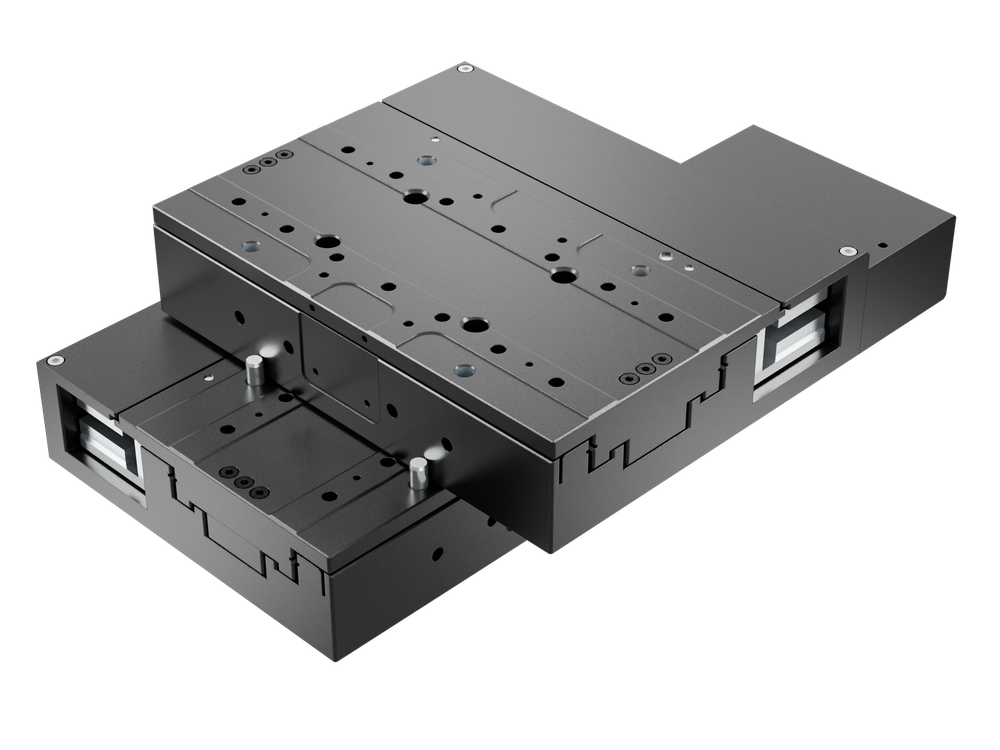
Table of Contents
Table of Contents
Disclaimer
Zaber’s products are not intended for use in any critical medical, aviation, or military applications or situations where a product's use or failure could cause personal injury, death, or damage to property. Zaber disclaims any warranty of fitness for a particular purpose. The user of this product agrees to Zaber's general terms and conditions of sale.
Precautions
 Collision Hazard! Zaber XY XYZ stages contain motion products with significant thrust and load capacities. Take caution to prevent collisions with operators, work surfaces, and sensitive equipment.
Heavy! Completely assembled products, partial assemblies and some stages can be very heavy. Exercise caution when lifting/moving larger assemblies and products. Loosely fasten stage axes as soon as they are placed during assembly, to prevent tipping and falling hazards.
 Important: XY XYZ products must be properly assembled and aligned to function optimally. Follow assembly instructions closely and contact Zaber Customer Support for help at any time, if needed.
Product Overview
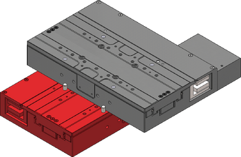
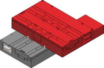
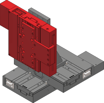
| X-Axis | Y-Axis | Z-Axis (Optional) |
 |
 |
|
Cable Lengths
For Zaber's direct drive XYZ systems, all data and motor cables provided are the same length, except if the system uses an integrated controller. For integrated controller systems, some length combinations will result in different length data cables - If applicable, the longer cable should be used in the connection between the Y and Z stage.
XY XYZ Stage Assembly and Setup
Zaber's XY XYZ stages require some assembly and set-up upon arrival. These XY XYZ stages can be disassembled, packed, and transported for use in new locations, or re-configured with new motion control axes to suit new applications. To set up your XY or XYZ stage, complete the following steps (where applicable).
Required Tools
- 5 mm hex key
Preparation
- Unpack the brackets, adaptor plates, and other hardware.
- Keep fasteners with their labelled bags to easily identify/locate the correct fastener for a step.
- Unpack the stage axes and identify the X-axis stage, Y-axis stage and the Z-axis stage if included. Refer to your purchase to determine which axis each stage belongs to.
- Typically the longest stage should be the X-axis. The Z axis looks visually different and includes a magnetic counterbalance.
- The X-axis and Y-axis ship with a shiping lock that must be removed prior to mounting the stage
- The Z-axis ships with a travel lock that must be removed prior to mounting the stage
- Determine your mounting surface. The instructions provided assume a metric optical breadboard is used to mount the X-axis stage.
- Determine stage orientations and location of the X-MCC controller, if included. The controller is typically located near the motor cable connections of the X-axis (lowest stage). If the controller is required to be mounted at a significant distance from the stages, longer cables or cable extensions may be necessary. See MC10T3(Lxxx) for longer 15 pin female to 26 pin male cables or MC10(Lxxx) for 26 pin female to 26 pin male extensions cables here: Zaber Accessories.
- Note: 'xxx' denotes a length in cm
Preconfigure Servo Tuning
Before assembling the system, adjust the servo tuning for the final load mass to ensure stable operation after assembly.
Connect the stages to your computer and power-up the stages. If the stages are peripherals connecting to an X-MCC controller, connect axes to the controller in the order you plan to use in the final system. See Cabling and Options section for more instructions on connecting your stages.
For each servo device follow the steps below in Zaber Launcher:
- In Device Settings, set driver.enable.mode to 0. This will leave the motor driver disabled at power-up or after a reset.
- This is not required, but is recommended while setting up the system to avoid unexpected motion immediately after power-up.
- Open the Servo Tuner App.
- Disable the driver.
- In the Simple tab, enter the load mass that will be on the stage in the final, fully assembled system. (e.g. For the X-axis, enter the combined weight of the Y-axis stage, Z-axis stage (if applicable), any adaptor plates or angle brackets, and payload that will be mounted to it).
- Weigh the stages and adaptor plates or look up the weights in the product specifications.
- Apply the tuning.
- Power off and disconnect the stage.
After performing these steps, do not enable the motor driver until the system is assembled. This tuning is potentially unstable without the weight of the stages and payload attached.
LDM X-Axis Stage to Breadboard
Assembly
-
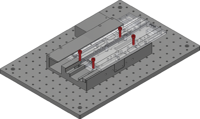
Loosely attach the X-axis stage on a breadboard or other mounting surface using the 4 provided M6x25mm screws and a 5 mm hex key by sliding the stage to one end of travel, exposing the pair of mounting holes. Move the stage to the other end of travel and repeat. Align the stage to your desired point of interest.
-
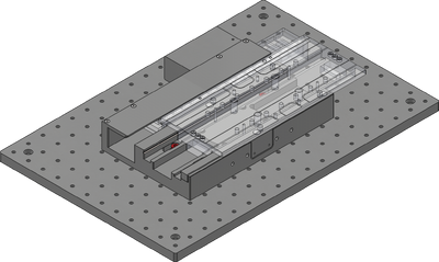
Firmly tighten down all fasteners mounting the X-axis stage.
LDM Y-Axis Stage to X-Axis
Assembly
-
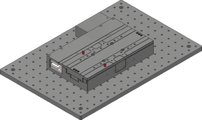
Insert the two included 6mmx14mm dowels in the holes shown to serve as alignment features.
-
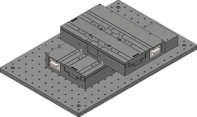
Align the edge of the Y-axis stage with the dowel pins
-
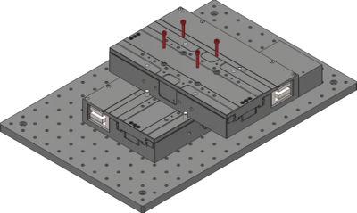
Keeping the stage at the center of travel, secure the upper-axis stage using 4 M4 x 25mm socket cap screws. Warning! Inserting screws that are too long can damage the lower-axis stage.
-

For systems with integrated controllers, a clip is included on the X-axis to allow for cleaner management of daisy-chain data cables.
LDM Z-Axis Stages to Y-Axis
This section is only applicable for XYZ stage products and can be ignored for XY stages.
Assembly
-
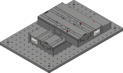
Insert two 6mm dowel pins into the holes shown
-
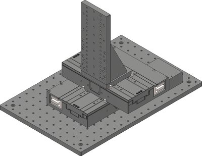
Align the edge of the Z-axis bracket AB255 to the dowel pins
-
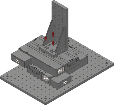
Attach the bracket using the provided M6 screws.
-
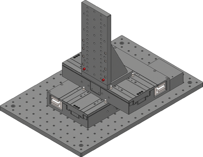
Insert two 6mm dowel pins into the holes shown on the Z-axis bracket
-
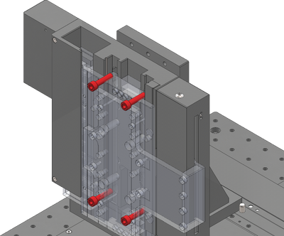
Unpack the Z-axis stage and attach the Z-axis stage using the provided M6 screws and a 5 mm hex key by moving it to the ends of travel.
-
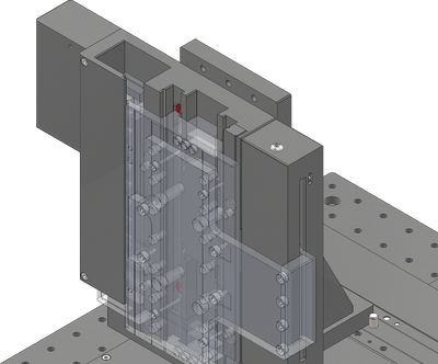
Tighten down the screws
Cabling and Options
-
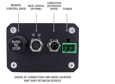
If using X-series Zaber stages with integrated controllers, then cabling is as simple as connecting the appropriate RS 232 data cables between each stage. These cables can be used to daisy chain both power and data, reducing clutter. For an XY stage, one data cable is needed, and for an XYZ stage, two data cables are needed. Refer to the cable table to determine which cables go where.
-
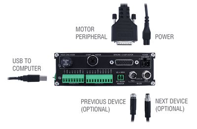
If using the X-MCC coordinated motion controller, then each stage needs to be directly connected to the controller with a motor cable. For an XY stage, two motor cables are needed, and for an XYZ stage, three motor cables are needed. Refer to the cable table to determine which cables go where.
-
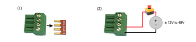
If using the X-MCC, the ES01 E-Stop accessory should also be installed at this point.
-
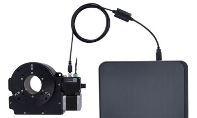
Connect the stage to the computer using the provided USB adaptor cable. This should be connected to the the X-axis stage (for X-series stages) or the X-MCC controller.
-
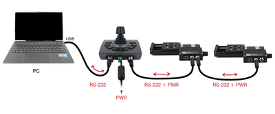
The optional joystick should be connected in-line between the computer and the X-axis stage (for X-series stages) or the X-MCC controller.
-
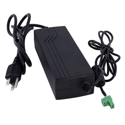
Power can be supplied to either the stages or the controller using the provided power supply brick. If multiple power supplies were provided, they should all be connected to the system to ensure sufficient current supply.
Device Product Manuals
Zaber's XY XYZ stage products are combinations of several Zaber motion control devices. For device operation, maintenance procedures and troubleshooting, consult the detailed product manuals for these devices:
- X-LDM-AE Linear Stage
- Provides X and Y axis linear motion in X-LDM-AE XY XYZ Stages.
- LDM-AE Linear Stage
- Provides X and Y axis linear motion in LDM-AE XY XYZ Stages.
- X-LDM-AEZ Linear Stage
- Provides Z axis linear motion in X-LDM-AE XYZ Stages.
- LDM-AEZ Linear Stage
- Provides Z axis linear motion in LDM-AE XYZ Stages.
- X-MCC Universal Drive Controller
- These controllers are available with 1-4 axes. In an XY XYZ stage, a two or three axis controller is typically used to provide coordinated motion for when the path by the system taken matters. This controller may be daisy-chained with other Zaber controllers or motion devices with integrated control.
- X-JOY3 Joystick
- Optional programmable joystick with 8 buttons allows for direct interaction with the XY XYZ stage.
Warranty and Repair
For Zaber's policies on warranty and repair, please refer to the Ordering Policies.
Standard products
Standard products are any part numbers that do not contain the suffix ENG followed by a 4 digit number. Most, but not all, standard products are listed for sale on our website. All standard Zaber products are backed by a one-month satisfaction guarantee. If you are not satisfied with your purchase, we will refund your payment minus any shipping charges. Goods must be in brand new saleable condition with no marks. Zaber products are guaranteed for one year. During this period Zaber will repair any products with faults due to manufacturing defects, free of charge.
Custom products
Custom products are any part numbers containing the suffix ENG followed by a 4 digit number. Each of these products has been designed for a custom application for a particular customer. Custom products are guaranteed for one year, unless explicitly stated otherwise. During this period Zaber will repair any products with faults due to manufacturing defects, free of charge.
How to return products
Customers with devices in need of return or repair should contact Zaber to obtain an RMA form which must be filled out and sent back to us to receive an RMA number. The RMA form contains instructions for packing and returning the device. The specified RMA number must be included on the shipment to ensure timely processing.
Email Updates
If you would like to receive our periodic email newsletter including product updates and promotions.
Contact Information
Contact Zaber Technologies Inc by any of the following methods:
| Phone | 1-604-569-3780 (direct) 1-888-276-8033 (toll free in North America) |
|---|---|
| Fax | 1-604-648-8033 |
| #2 - 605 West Kent Ave. N., Vancouver, British Columbia, Canada, V6P 6T7 | |
| Web | www.zaber.com |
| Please visit our website for up to date email contact information. |
The original instructions for this product are available at https://www.zaber.com/manuals/LDM-XY-XYZ.
Product Drawings
Specifications
| Specification | Value | Alternate Unit |
|---|---|---|
| Weight | 1.5 kg | 3.307 lb |
| CE Compliant |
This product uses the FreeRTOS kernel. FreeRTOS is © 2026 Amazon.com, Inc. or its affiliates and is governed by the following license:
All rights reserved.
Permission is hereby granted, free of charge, to any person obtaining a copy of this software and associated documentation files (the "Software"), to deal in the Software without restriction, including without limitation the rights to use, copy, modify, merge, publish, distribute, sublicense, and/or sell copies of the Software, and to permit persons to whom the Software is furnished to do so, subject to the following conditions:
The above copyright notice and this permission notice shall be included in all copies or substantial portions of the Software.
THE SOFTWARE IS PROVIDED "AS IS", WITHOUT WARRANTY OF ANY KIND, EXPRESS OR IMPLIED, INCLUDING BUT NOT LIMITED TO THE WARRANTIES OF MERCHANTABILITY, FITNESS FOR A PARTICULAR PURPOSE AND NONINFRINGEMENT. IN NO EVENT SHALL THE AUTHORS OR COPYRIGHT HOLDERS BE LIABLE FOR ANY CLAIM, DAMAGES OR OTHER LIABILITY, WHETHER IN AN ACTION OF CONTRACT, TORT OR OTHERWISE, ARISING FROM, OUT OF OR IN CONNECTION WITH THE SOFTWARE OR THE USE OR OTHER DEALINGS IN THE SOFTWARE.
This product uses the LZ4 compression library. LZ4 is © 2011-2016 Yann Collet and is governed by the following license:
All rights reserved.
Redistribution and use in source and binary forms, with or without modification, are permitted provided that the following conditions are met:
- Redistributions of source code must retain the above copyright notice, this list of conditions and the following disclaimer.
- Redistributions in binary form must reproduce the above copyright notice, this list of conditions and the following disclaimer in the documentation and/or other materials provided with the distribution.
THIS SOFTWARE IS PROVIDED BY THE COPYRIGHT HOLDERS AND CONTRIBUTORS "AS IS" AND ANY EXPRESS OR IMPLIED WARRANTIES, INCLUDING, BUT NOT LIMITED TO, THE IMPLIED WARRANTIES OF MERCHANTABILITY AND FITNESS FOR A PARTICULAR PURPOSE ARE DISCLAIMED. IN NO EVENT SHALL THE COPYRIGHT HOLDER OR CONTRIBUTORS BE LIABLE FOR ANY DIRECT, INDIRECT, INCIDENTAL, SPECIAL, EXEMPLARY, OR CONSEQUENTIAL DAMAGES (INCLUDING, BUT NOT LIMITED TO, PROCUREMENT OF SUBSTITUTE GOODS OR SERVICES; LOSS OF USE, DATA, OR PROFITS; OR BUSINESS INTERRUPTION) HOWEVER CAUSED AND ON ANY THEORY OF LIABILITY, WHETHER IN CONTRACT, STRICT LIABILITY, OR TORT (INCLUDING NEGLIGENCE OR OTHERWISE) ARISING IN ANY WAY OUT OF THE USE OF THIS SOFTWARE, EVEN IF ADVISED OF THE POSSIBILITY OF SUCH DAMAGE.