Extending Your Robot Arm’s Reach: The Role of 7th Axis Linear Stages
By Mark Preddy, Sustaining Engineering Team
Published on Oct. 29, 2025
The recent proliferation of collaborative robots has changed the way we make, process, and handle many products. Maximizing the efficiency of your cobot and minimizing your overall system cost are critical factors for successful process automation. One tool to help you make the most of your cobot is a 7th axis linear stage. A 7th axis linear stage is a motorized linear stage that can precisely move your robot to another location. 7th axis stages are also known as robot transfer units (RTU’s), robot slides, range extenders, or robot shuttles.
This article will help you understand when you should consider using a 7th axis linear stage with your robot arm and how to integrate it into your automation projects. We will review:
- Work Envelopes and Process Integration
- Cost Trade Offs
- Stage Selection and Considerations
- Stage Mounting
- Communication and Control
- System Safety
When You Should Consider a 7th Axis Linear Stage
1. Optimizing Work Envelope and Workflow
A 7th axis allows you to optimize the layout of your robot cell’s working envelope. People often think of a work envelope simply in terms of area, however the shape of the work envelope is often much more important.
Consider the two cases below for example:
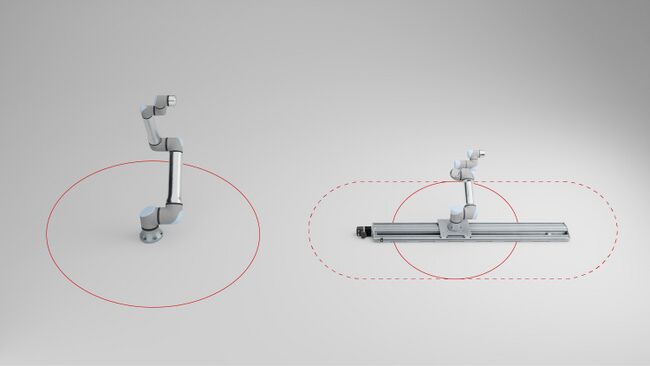
Figure 1. Case A (left) featuring a single robot arm and Case B (right) featuring a robot arm mounted to a linear stage.
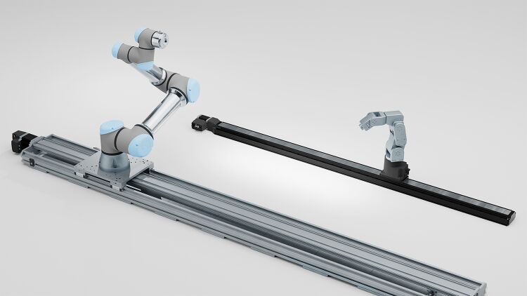
Case A uses a single long reach robot arm and has a circular work envelope. This can be very useful in many applications such as pick and place, sorting, or transfer. This case is also ideal for scenarios such as replacing a stationary human worker at a compact workstation.
Case B utilizes a short reach robot arm with a long travel 7th axis and features an obround work envelope. These systems are often more intuitive to integrate into production lines as they more closely mimic the work flow of a mobile human worker that they are meant to replace or complement. They can easily be retrofitted into existing assembly lines. They are ideal for working around obstacles or transferring items between processes.
2. Simplifying Expansion of Existing Systems
A 7th axis can simplify the expansion of an existing robotic system. For example, an automated machine tending system can be expanded to provide additional part storage capacity. Adding a 7th axis and duplicating the existing storage racks allows for almost all of the robot motion programming to be reused. All of the robot path planning at the machine side remains the same as well. If a larger robot arm is used instead, the storage racks will likely need to be redesigned to fit the working volume of the new arm and the robot path planning at the storage racks and at the machine side will need to be recreated because of the different geometry of the new arm.
3. Maximizing Reach for Your Investment
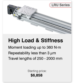
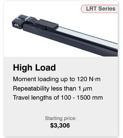
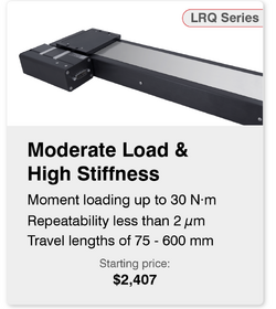
A 7th axis is the most cost-effective way of increasing the work envelope of your system. Robot arm costs vary significantly with manufacturer, reach, payload, and accuracy. However, robot arms across the board are much more expensive when compared to 7th axis stages. Reach can typically be maximized for a given budget by utilizing a small robot and a 7th axis stage versus a large robot. The starting costs for Zaber stages we recommend for use in 7th axis applications are:
Implementation Guide: Key Considerations for a Successful 7th Axis Setup
7th Axis Linear Stage Selection
Accuracy and Repeatability Definition
At first glance, accuracy might seem to be the most important positioning characteristic when selecting a linear stage as a 7th axis. However, repeatability is often the critical spec for real-world applications. Repeatable moves allow both the stage and robot to return to the same position every cycle, ensuring consistent and predictable processes. The repeatability spec of your 7th axis stage should be as good as or better than your robots.
Loading Considerations
Most linear stages' maximum centered load capacity and maximum moment capacity far exceed that of the robot arms that can be mounted to them. However, to ensure system reliability and lifetime, it is critical to calculate the worst case loading scenarios of your system and ensure they do not exceed any of the maximum specs of the linear stage. Pitch, roll, or yaw stiffness of the 7th axis may also be an important specification to consider, especially if the robot is handling heavy components. A low stiffness stage with a significantly changing payload on the robot's end effector may not meet your positioning requirements.
For example, consider an LRT stage with 700 N⋅m/° roll stiffness. If you apply a 10 kg load to a robot's end effector, 1 meter off the center of the stage, approximately 100 N⋅m, you can see up to 2.5 mm of downwards deflection. We can expect this deflection to be repeatable, but if you then remove the load, the end effector will spring upwards towards its zero deflection position. This can still often be accommodated with thoughtful end effector or pathing design.
Special Considerations for Vertical Loads
Along with specifying the load capacity and moment loading required of the stage, stage thrust and backdrive force must also be taken into account if the stage will be mounted in a vertical orientation. A 7th axis linear stage used in a vertical application must not backdrive when power is lost. A backdrive condition can lead to robot, payload, and stage damage or injury to people near the system. To prevent this, a vertical stage should be loaded so as to not exceed the backdrive force. If this is not possible, the stage should either use a fine pitch, self-locking screw or be equipped with a motor brake.
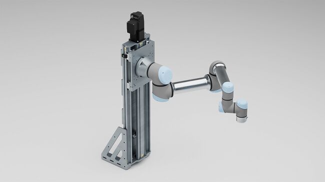
Figure 2: A Zaber LRU linear stage with a brake mounted vertically to extend the work envelope of a robot arm.
Physical Mounting and Integration
Stage Mounting Best Practices
Recommended practices for mounting 7th axis stages are highly dependent on the application. In general, mounting to a strong, stiff, and flat surface while using all of the stage's mounting holes will yield the best system performance. Some options for mounting are:
- Welded structures
- Extrusion-based frames
- Tooling plates
- Optical tables
- Concrete flooring
When selecting a substrate to mount to, care must be taken to ensure the mounting surface is sufficiently flat, otherwise stage performance and lifetime will be compromised. The best practice to maximize stage performance is to mount to a metrology grade granite or a comparably flat surface. However, an optical breadboard or tooling plate with flatness of around ±0.15 mm per 300 mm is usually sufficient for all but the most demanding applications. Flatness worse than ±0.25 mm per 300 mm will likely reduce device lifetime and significantly reduce performance.
Make sure the 7th axis stage can be mounted in the orientation you intend. For example, Zaber stages are designed to be mounted in any orientation, but many stages are restricted to specific orientations. Some bearing support systems are not always multi-directional and their intended mounting orientation is directly flat to a horizontal surface.
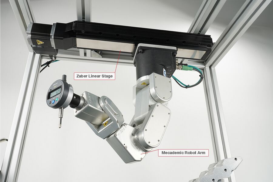
Figure 3: A Mecademic Meca500 robot arm with a Zaber LRT 7th axis stage mounted upside-down for a space constrained application.
Mounting Robot Arms to 7th Axis Stages
There is a huge range of robots available, and there is currently no widely adopted mounting standard. Most robots will require an adaptor plate to mount to a 7th axis. Zaber’s LRU family of linear stages provides 93 mm, 120 mm, and 150 mm square patterns with M8 fasteners. This allows for direct mounting of many popular robots from manufacturers including Universal Robots, Fanuc, Doosan, Kuka, Dobot, Elite Robots, and Jaka. Stage suppliers, including Zaber can also provide custom brackets to mount your robot to the stage of your choice.
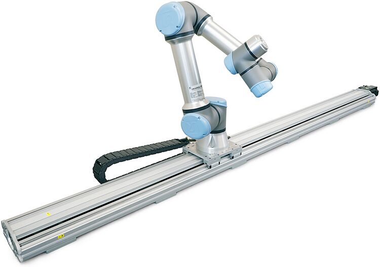
Figure 4: Universal Robots UR5 directly mounted to Zaber LRU 7th axis linear stage without additional adaptors.
Cable Management Considerations
Best practices for cable management are highly application dependent. The quality of the cables supplied with robots can vary greatly between manufacturers, and many robots do not include high flex life cables as standard. In addition to selecting a cable with the correct type of bend rating, the cable’s bend radius must also be considered. The recommended minimum bend radius is highly dependent on cable construction and should be confirmed with the manufacturers datasheet. If your robot's cable isn’t rated for dynamic bending, or the bend radius is excessive, a custom cable management solution can help ensure that your cable will achieve its desired lifetime.
Unmanaged or loose cables can result in premature failure due to tangles or excessively tight bend radii. Caged cable chains are a great way to manage cables on a linear stage. Zaber’s CG line comes in a variety of sizes to meet more compact requirements, but some large end effector systems might require a non-standard solution.
Synchronizing Robot Arms & 7th Axis: Communication and Control
Robot controllers, PLC’s, or PC’s can all be used to control the robot along with the 7th axis. How the 7th axis and robot communicate to each other is highly dependent on both devices' available communication methods. Like the physical mounting of the robots, there is no universal communication standard for robots or 7th axis stages, so each case will depend on the manufacturer of the robot and 7th axis, and systems integrator's preferences.
Approach 1: Treat your 7th Axis as an Independent Axis
The best way to integrate a 7th axis with your robot controller is to treat the 7th axis as a separate closed loop motion device. This approach doesn’t support fully-synchronized motion between the robot and the linear stage but this often isn’t a requirement for all but the most throughput-optimized applications. Attempting fully-synchronized motion may be undesirable in situations where the robot safety systems depend on the robot knowing and calculating the mass and velocity of its payload. These systems compare the actual measured force to a calculated force to decide if a collision with the robot has occurred. Attempting synchronized motion with the 7th axis will introduce unaccounted acceleration and deceleration forces to the robot which might trigger these safety features.
Zaber devices have four different hardware interfaces that can be used to communicate with the 7th axis:
- TCP/IP
- EtherCat
- RS232/USB
- Digital IO with Optional Encoder Output
Zaber devices communicate via ASCII commands and can be programmed using our comprehensively documented Zaber Motion Library API which supports languages including Python (our most popular), C#, C++ JavaScript, Octave, Matlab, Java, Labview, and even Arduino.
Approach 2: Use Inputs and Outputs for Simplicity
To keep communication as simple as possible between the robot and 7th axis, another approach aside from those mentioned above is to use digital IO’s or encoder outputs. Zaber’s MCC controllers have four isolated digital inputs and four isolated digital outputs which can be combined with pre-programmed triggers. Integrating these IO’s with an encoder output from the 7th axis can further increase the control you have over the stage.
Approach 3: Third Party Software Control
Visualizing the motion profiles of your robot and the 7th axis can help develop complex movement sequences in space-constrained environments. The RoboDK software package supports a wide range of robots along with many Zaber stages, making such simulations easy. Supported robots and stages can also be programmed and controlled via RoboDK’s software. This approach is similar to the first and will utilize the same communication hardware interfaces.
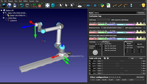
Figure 5: A Zaber LRU 7th Axis and Universal Robots UR5 simulated in RoboDK’s virtual environment
Approach 4: Third Party Controllers or Motors
Many users and systems integrators are most comfortable using familiar controllers and motor systems. To increase integration flexibility, Zaber offers controller-less and motor-less stages. This allows users to either use their own controller or controller-motor combinations to best integrate with existing motion control ecosystems.
Safety Recommendations
When integrating a 7th axis into your robotic application, user safety should be at the forefront of your design consideration. Large loads, unexpected movement, changing speeds, pinch hazards, and power loss can all contribute to a potentially dangerous environment for a human to be around.
To mitigate these risks, several key safety mechanisms and best practices should be integrated into the system's design:
Pinch and Entrapment Minimization
While pinch or entrapment risks may not be present on a robot or 7th axis individually, unexpected risks may be created as motion equipment is integrated together. It is critical to do a full system risk analysis and ensure new hazards are either not created, or are eliminated through clever system design or guarding and isolation of dangerous areas.
Emergency Stop and Safe Torque Off
Integration of an Emergency Stop (E-stop) circuit with your robot's E-stop system is highly recommended. The 7th axis system should also have a Stage Torque Off (STO) function, which cuts power to the motor but keeps the controller powered and able to communicate. Zaber peripheral controllers, such as the X-MCC and E-MCC, have E-stop support which provides STO.
Stall and Collision Detection
7th axis stages do not typically come with force sensing capabilities, so extra care must be taken to ensure human and process safety is maintained. Care must also be taken when programming the 7th axis so that it doesn’t accelerate fast enough to trigger the robot's collision detection, if equipped. While Zaber stages do not support force sensing at the time of this article's writing, they do have adjustable stall detection thresholds that can be set to stop motion if something causes the stage to deviate from its expected trajectory.
Power-off Brakes
Brakes are also available to keep loads stationary, prevent unexpected movement, and stop the stage in case of an emergency. For vertical orientations, power-off brakes stop uncontrolled back-driving and are a critical safety feature to protect users and the system in the event of a power loss.
Conclusion
A 7th axis linear stage can be one of the most cost-effective and flexible ways to increase the value of your cobot automation solution. By choosing the right stage, mounting strategy, and communication method, you can improve system performance and versatility while keeping costs and complexity to a minimum. Contact our knowledgeable Application Engineering team to discuss how best to select a 7th axis linear stage from Zaber Technologies.