Emergency Stops (E-Stops)
By Alex Canan, Applications Engineering Team
Published on Jul. 27, 2022
An emergency stop provides a method for a motion control system to quickly enter a safe state, either by removing power from moving parts or bringing the system to a controlled stop. This can help protect equipment and keep nearby operators safe. It is an important component for many motion control applications. This article will cover how Zaber’s emergency stop (E-stop) works and how you can implement an emergency stop with a Zaber device. The characteristics of an E-stop can vary depending on the type of stage you are using. The friction of a stage’s drive mechanism can cause the stage to immediately come to a halt or coast to a stop. This is important for understanding how Zaber’s E-stops work when you pair them with your stages and it will be discussed in more detail later in this article. Zaber offers an easy-to-use E-stop feature on the MCC controller family. The E-stop allows a user to instantly implement a Safe Torque Off (STO) E-stop.
What is Safe Torque Off?
Safe Torque Off (STO) is the most common implementation of E-stop in which driver current is prevented from flowing into the motor. In most implementations, including Zaber’s, the controller remains powered and is able to report the fault.
Using E-stops on Zaber’s MCC Controller
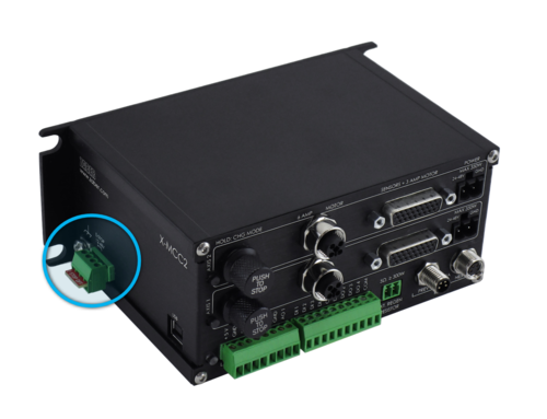
The MCC controller family features an E-stop input that can be connected to a 12–48 V power supply and a normally closed switch. Cutting power to the E-stop input will cause the controller’s axes to immediately enter STO. The motors of these axes will lose power, but the controller itself remains operational.

Cutting power and re-starting Zaber devices will not damage their electronics. Keeping the controller powered during an E-stop has several advantages:
- Settings and device state will persist. If your device has an encoder, it does not need to be homed following an E-stop because the controller is still tracking position.
- You can adjust settings, monitor device position, and read messages from the devices (for example, warning flags that report the E-stop was triggered).
- If there are triggers configured using conditions that will be triggered during the E-stop, such as axis velocity falling to zero or motion.busy reporting idle, the triggers will fire and any non-motion actions will execute.
- If any devices are daisy-chained downstream of the MCC, they will still be able to communicate with software.
- The E-stop is latching. You will need to explicitly re-enable the driver to be able to use your devices again (with a driver enable command).
To use the MCC E-stop you can use Zaber’s ES01 emergency stop kit or make your own emergency switch. Please see the X-MCC User's Manual for more information on how to set up an E-stop.
Understanding How Zaber Stages Perform During an E-stop
When the E-stop is triggered on an MCC controller, the axes’ motors lose power. However, the motors losing power does not always cause the stages to immediately stop. Evaluating how your stages will move after an E-stop is triggered comes down to two key aspects:
- the internal friction of the stages’ drive mechanism
- the momentum of the payload
Below, we will look at two examples to demonstrate the differences in stage E-stop behavior.
These are just quick generalizations. To better explain the stopping behavior, two examples are covered below to show this difference in greater detail.
Example 1. High-speed belt-driven gantry (a low friction system)
Zaber’s belt-driven stages are often used for high-speed applications.
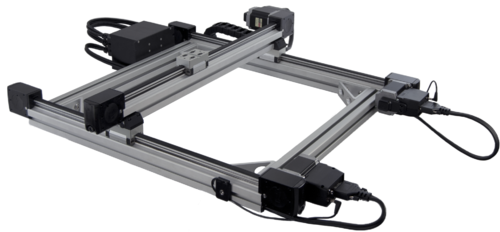
In this example, a 1000 mm X 1000 mm LC40 gantry system is moving a 10 kg payload at 1.5 m/s in the X and Y direction. During operation, the user realizes there is an object in the path of travel and immediately presses their E-stop. At this moment, the payload is 500 mm away. All of the LC40 Gantry’s motors enter STO causing the gantry to immediately slow down -- but the gantry does not stop. The gantry slowly coasts until it hits the object 500 mm away. The impact speed is much slower than the original 1.5 m/s speed. This low impact collision prevents the stage and the object from being damaged.

Example 2. Fine-pitch lead screw in a vertical application (a high friction system)
In this second example, an operator is using an LRT0500AL-E08CT3A stage vertically (which has a fine-pitch lead screw) with an MCC controller and E-stop. The stage is holding a 5 kg payload in place. The operator wants to make sure that this stage will not move while their colleague is nearby, so they press the ES01 E-stop before the colleague gets close to the stage. The E-Stop immediately stops the device. When the E-stop is engaged, the LRT0500AL-E08CT3A will not move. This is because the fine-pitch lead screw on this LRT cannot back-drive. The stage will not move until the operator restores power to the MCC E-stop input and re-enables the motor driver.
Integrating a safety interlock switch with Zaber’s X-MCC E-stop
One way to combine the MCC controller’s E-stop feature with Zaber's other X-Series features to enhance safety is to use an interlock for an application with an enclosure. Below is an example of how specific commands can be set up to enable this usage on an X-MCC controller.
1. Locking the enclosure door while the stage is moving.
Door interlocks typically have two main functions: locking the door when a digital input is set to high, and outputting a signal that indicates whether the door is open or closed. The first part, safety locking the door, can be done automatically whenever the devices are moving by creating a trigger that sets a digital output on the X-MCC depending on whether the stage is in motion (monitoring motion.busy). The following ASCII commands tell the controller to set digital output #3 to HIGH every time the stage is active (this is trigger #1) and to set digital output #3 back to low when the stage is inactive (this is trigger #2).
/01 trigger 1 when motion.busy == 1↵
/01 trigger 1 action a io set do 3 1↵
/01 trigger 1 action b none↵
/01 trigger 2 when motion.busy == 0↵
/01 trigger 2 action a io set do 3 0↵
/01 trigger 2 action b none↵
You can then link these digital output signals to the door interlock switch. This will prevent anyone from accidentally opening the enclosure while motion is in progress.
2. Enabling the X-MCC E-stop when the enclosure door is open
To take advantage of the second door interlock feature, monitoring whether the door is opened or not, you can create a circuit between the X-MCC E-stop pins and interlock switch. Set the switch to disconnect power to the X-MCC E-stop pins, so the E-stop will trigger every time the door opens. To disable the E-stop state, you will need to close the door and send a command to enable the driver (driver enable). With these precautions, a user should never be able to access the device when it is in motion, or start a motion while access to the device is available.
Alternative Solution for Devices with Built-In Controllers
Some Zaber devices—for instance, devices with built-in controllers such as the X-LSM—do not have a dedicated E-stop input by default. There are other E-stop solutions available in these scenarios. The most common is to use a power supply switch. This can be set up by the user or Zaber can provide custom power supplies with an in-line switch. Similarly to the E-stop, using a power supply switch on a device with a built-in controller also removes motor current and it also has a latching response. However, there are some key downsides to this approach:
- It prevents all communication to the device and any downstream devices.
- The stage will need to be powered on and homed after every power disconnect.
- The large capacitance in the driver acts as a local power supply, and can cause a delay between the time that input power is disconnected and the time that the motor begins to decelerate.
In some applications these considerations might not be a problem and the smaller size and cheaper cost of a power supply switch is more important. In particular, this solution may be best suited for systems with small single devices. For more complex systems, or for systems with high inertia, Zaber recommends the use of an MCC controller with dedicated E-stop inputs.
Conclusion
Zaber's devices with a dedicated E-stop feature, like the MCC controller family, can provide customers with many benefits. If you are interested in adding an E-stop to your Zaber device, it is important to understand how Zaber’s STO behaviour will work with your specific Zaber motion devices. This will help you to make sure that you meet the safety requirements for your application. If you have a potential application in mind, or if you would like to better understand how an E-stop would work, please feel free to email our Applications Engineering Team at contact@zaber.com.