Encoder Output Options for Near Real-Time Synchronization
By Dan Came, Product Manager
Published on Jul. 25, 2025
For many advanced applications, from linescan imaging to laser processing, success depends on precise, real-time synchronization between motion devices and external systems like cameras, lasers, or data acquisition hardware.
Choosing the right synchronization method is key to unlocking the full potential of your automated setup. In this article, we will explore a few popular techniques and provide a detailed description of Zaber’s encoder output options.
Dead Reckoning: Simple & Predictive
The most straightforward approach is dead reckoning. This method predicts the stage's position by calculating its trajectory from known parameters, like acceleration and maximum speed. It's a fantastic starting point because it's simple to implement and requires no extra position-sensing hardware. The main consideration is that it operates without active feedback, so predicting the exact path and timing can become more challenging for complex, multi-axis movements.
Position Polling: Easy Software-Based Feedback
For active feedback, you can tap into the Zaber controller's communications. Our powerful APIs make it incredibly easy to continuously poll the controller for an axis's current position using your own software. This gives you direct insight into what the device is doing. Keep in mind that the polling rate is typically between 50-500 Hz, and the timing between each data point can have a jitter of up to 5 ms, depending on your communication port and software load.
Digital Triggers: Fast & Precise Events
For high-speed applications, digital triggers are a game-changer. You can configure the controller to fire a digital pulse with a precision of 0.1 milliseconds the instant a specific condition is met, such as reaching a target position. This method is incredibly fast and reliable. To learn more, check out our detailed articles on using triggers and synchronization for imaging applications.
Direct Encoder Feedback: The Ultimate in Real-Time Sync
This is the gold standard for high-performance synchronization. If your external system can read an encoder signal, you can stream position data directly from a Zaber device equipped with an encoder. This gives your instrument real-time, high-frequency access to the stage's exact position with no intermediate software required. The key is ensuring hardware compatibility, and that's where we shine. Zaber offers tremendous flexibility in configuring encoder signal outputs to match a wide variety of instruments. The rest of this article will cover the options Zaber offers for matching a compatible encoder output for your instrument.
Encoder Output Options from Zaber
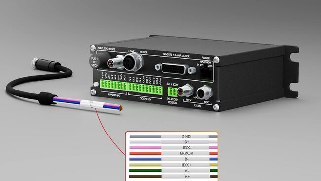
To achieve near-real-time integration of third-party systems with Zaber positioners, Zaber’s MCC controllers offer optional encoder output ports for up to four motion axes using the same encoder output type. Those ports pass the encoder signals from compatible Zaber peripheral positioners with encoders through included 1.5m cables with labelled flying leads that users can connect to an external system. An example of this for a 1-axis X-MCC is shown below.
Encoder Signals
To determine which Zaber MCC is required, you will need to assess:
- How many axes the controller should control, and which Zaber axes you want to connect.
- How many of those axes require encoder outputs.
- What type of signal the encoders on those axes use.
- What type of signal your instrument is expecting.
Since matching encoder signals is the main pain point in this process, it’s worth quickly explaining some common encoder formats and terms:
Quadrature Signal - this term describes a two-phase encoder signal where the phases are offset from each other by a quarter-cycle. As the states change, the encoder counter will either add or subtract to the count. This is the common encoder format for relative encoders.
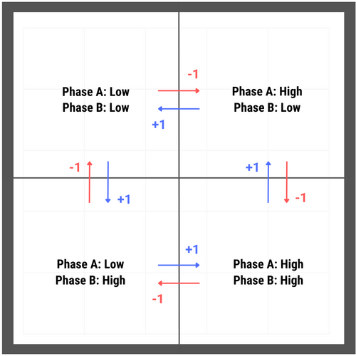
Relative Encoders - encoders will either be relative, meaning they use the power-on position as the 0 point for counting, or absolute, meaning the encoder knows where in travel the axis is when powering on. While relative encoders use quadrature signals, absolute encoders often use one of several serial communication formats.
Digital and Analog Signals - for Zaber devices, this represents what signal the Zaber controller is measuring. A digital signal is represented by high and low states, while an analog signal has a range of states that the controller must interpolate down to a digital representation.
Single-Ended Signal - a format that compares the voltage in a phase to ground in order to determine if the signal is in a ‘high’ or ‘low’ state. ‘TTL’ is a common single-ended digital format that uses 0 to 0.8VDC for low, and 3-5VDC for high.
Differential Signal - a format where a phase is made up of a ‘+’ and ‘-’ line which are the inverse of each other. The - line voltage is subtracted from the + line voltage; if the result is a positive voltage the signal is high, while if it is negative the signal is low. Differential signals help cancel noise, so they are good for signal that must switch with high frequency and where long cable lengths are required. ‘RS422’ is a common digital differential format which uses +2 to +6VDC for high, and -2 to -6VDC as low.
Motor Encoders and Direct Encoders - motor encoders are mounted to the shaft of the motor, while direct encoders measure the movement of the moving positioner directly. Motor encoders are used by Zaber controllers for stall detection and correction, while direct encoders can additionally be used to improve positioning accuracy.
Zaber's Encoders
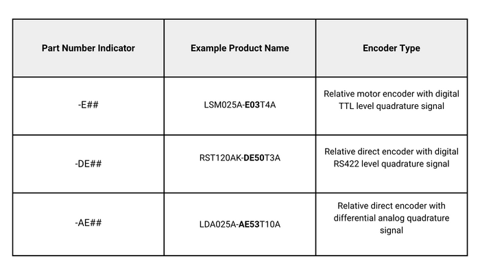
Zaber’s devices currently use three different encoder types, designed with different part number indicators in their model name. See the table below for a summary of these:
Output Options
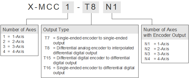
While the nature of the encoder signals is set by the hardware of the axis, it may not match what nature of signal your instrument expects. To manage this, we can either pass through or convert the signal to several common formats. Find below a table with those output formats, along with the MCC code that matches the combination of axis and output encoder types.
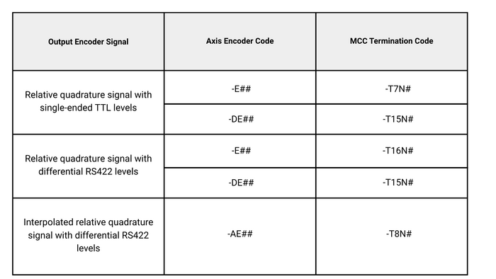
These are also captured in the series reference table here for the X-MCC series:
Interpolated Output Benefits
It’s worth highlighting a feature of the ‘-T8N#’ option in the table above. An analog signal must be interpolated to be interpreted as a ‘count’. For example, if the analog signal had a cycle distance of 20 um, then a 100X interpolation rate would mean that the distance per count is 200 nm. Zaber’s controller uses an interpolation factor when evaluating the signal, but the user can specify a separate interpolation rate that determines the cycle length of the output signal, anywhere from 4X to 4096X. This helps the user manage the maximum frequency of the output signal, which is discussed more below.
Additional Considerations
Some other considerations to be aware of:
- Instruments that read encoder signals will typically have a rating for their reading rate, often specified in kHz or MHz. You should ensure that the encoder output will not switch at a rate higher than this frequency. One way you can do this is by limiting the maximum speed you target; for example if an encoder count size is 10um and the instrument can read at a maximum of 100 kHz, then the maximum speed you should move at is 10 um * 100 kHz = 1 m/s. For ‘-T8N#’ outputs, you can also change the output frequency by setting interpolation rate to be coarser.
- The ‘-T15N#’ outputs update at a 10MHz rate. It’s strongly suggested that in order to avoid missed counts, any instruments reading this output have a reading rate of at least 10MHz.
- Need some combination of -T7, -T8, -T15, and -T16 on one MCC? Contact us! We’re able to generate these on a case by case basis, even if they aren’t listed online.
- Zaber calibrates direct encoders (-DE and -AE) during manufacturing and the Zaber controller uses that calibration to improve accuracy. If you are using one of these devices, we can provide the calibration values at no cost for you to manually apply if this improvement is needed. Contact us about it!
- The TTL/RS422 signal levels provided by Zaber encoder outputs are directly compatible with many systems; however, for other applications requiring different logic levels (such as 3.3 V), a voltage-level converter may be required.
- To use Zaber positioners with integrated controllers instead of peripheral positioners and an MCC controller, encoder outputs are available on some integrated devices as custom products. Not all integrated devices can accommodate all output options. Contact us with a request and we will accommodate it if we can.
Conclusion
Integrating external systems with Zaber stages using quadrature encoder outputs enables precise motion control and synchronization. By carefully considering the system requirements and the capabilities of Zaber's encoder outputs, you can achieve seamless and accurate motion control. For more detailed information, consult our online manual. For custom encoder output wiring options or custom encoder outputs for Zaber devices with built-in controllers, contact us to speak with our knowledgeable Application Engineering Team.