
T-CON Series User's Manual
Zaber device controller
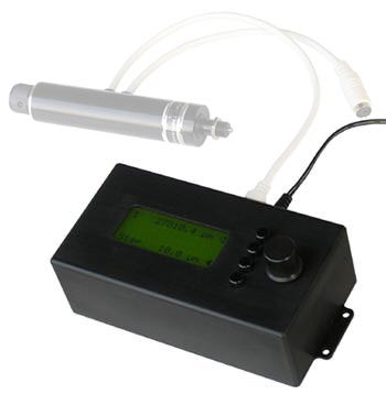
Table of Contents
Table of Contents
Disclaimer
Zaber’s products are not intended for use in any critical medical, aviation, or military applications or situations where a product's use or failure could cause personal injury, death, or damage to property. Zaber disclaims any warranty of fitness for a particular purpose. The user of this product agrees to Zaber's general terms and conditions of sale.
Introduction
Features
Features of the T-CON3 controller include:
- Easy-to-read 16 characters x 4 line backlit high-contrast LCD display
- Compatible with most of Zaber’s T-series devices
- Display and control the exact position for up to three axes
- Rotary encoder knob with detents for rapid and precise motion control
- Function keys for rapid selection of devices and features
- Small form-factor takes up less room on a work bench than a computer
- Intuitive and powerful user interface saves time
- Plug-and-play, no programming required

Compatibility
The T-CON3 is designed specifically to control Zaber’s T-series motorized devices. At the time of writing, the T-CON3 is compatible with the following product lines:
- T-LA series Miniature Linear Actuators
- T-HLA series Heavy Duty Linear Actuators
- T-LS series Motorized Linear Stages
- T-LLS series Motorized Dovetail Slides
- T-MM series Motorized Mirror Mounts (2 axis device)
- T-CD series Stepper Motor Controller
- T-NM series Stepper Motor with Controllers
- T-LSR series Motorized Linear Slides

Note: The T-CON3 is NOT compatible with T-JOY3 Programmable Joystick Controller.
Applications
Up to three devices (1 axis per device) may be daisy-chained with a single T-CON3 controller. While any number of Zaber T-series products may be connected directly to the serial port (RS232) of a personal computer, the T-CON3 controller can still replace the PC in many situations and offers some unique advantages.
| Feature | T-CON3 Controller | PC running Zaber demo software or customer software |
| Maximum number of devices | 3 | 254 |
| Size of controller | W: 75mm(3”), L: 140mm(5.5”), H: 65mm (2.5”) | Size of customer’s computer or laptop |
| Rotary knob with detents for rapid and precise motion control | Yes | No |
| Function keys for rapid selection of devices and features | Yes | Depends on Software |
| Simplified user interface for ease of use | Yes | Depends on Software |
| Programming required | No | Yes if required control is beyond the scope of Zaber Console or demo software |
| Programmable move sequences and trajectories | No | Yes with Zaber Console scripts or custom control software |
The T-CON3 controller is a great complement to Zaber’s T-series motorized devices in many application scenarios:
- Remote control and readout of a motorized actuator such as our T-LA series, for example, motion control in a vacuum chamber.
- Simple manual step and repeat operations with user-specified step size. One click of the rotary encoder moves a user-specified distance.
- Controller box makes it easy to set up an experiment initially without a computer, with the potential to automate the process afterwards.
- Replaces digital micrometers with a full-featured motorized micrometer.
- Small footprint saves space on a workbench compared to using a computer or other bulky controller devices.
Quick Start Guide
This section describes how to get the controller up and running. The quick start guide assumes that the user has the following components ready:
- T-CON3 controller
- One or more T-series motorized products (T-LA series, T-HLA series, T-LS series, T-LLS series, T-MM2 series, etc)
- 12V Power supply with 2.1mm center-positive plug
Power Up
The first step is to verify that the controller powers up by itself. Do not connect any actuator to the controller yet. Plug the 12V power adaptor into a live power bar or live wall socket. Plug the power plug into the T-CON3 controller to power up the device. There is no separate power switch. The LCD backlight should be lit and the splash screen will be displayed.

The controller will immediately begin searching for any connected actuators. Since no actuator is connected, after trying to initialize for about 2 seconds on the splash screen, the controller will display on the lowest line “Device not found”. Then it will attempt to search for devices again, finally giving up and displaying the following screen:

The above screen verifies that the device powers up and is working properly. Pressing the button next to “Retry” will instruct the controller to search for external actuators again, and return to the same screen if no actuators are found.
Establish Connection
Now, connect one of Zaber’s T-series actuators to the controller. If the actuator has a knob on the end, make sure the knob is centered or it may interfere with the initialization process. In this example we assume that only one T-LA28A actuator is connected, though up to 3 actuators can be controlled. Press the button next to the clear arrow next to the words “Retry”. The controller will try to initialize again.

This time it should display the above message if you have a T-LA28A actuator connected. Now you may either press the button next to the clear arrow, or simply wait 3 seconds for the next screen to be displayed:

The “1” in the upper left hand corner indicates the device number, while the “282879 bits” indicate the actuator’s position. When the actuator powers up, the internal position counter of the actuator defaults to the maximum extension. This is done to prevent over-extension of the actuator before the actuator is homed and the position counter is reset to zero.
Moving the Actuator
Press the button next to the top line. The arrow turns black indicating that the line is selected. When a line displaying an actuator is selected, turning the knob will cause the actuator to move by the step size shown on the bottom line.
Try turning the knob counterclockwise, which causes the actuator to retract the leadscrew. If the knob is turned counterclockwise sufficiently, the actuator will hit the home switch and reset the internal position counter to zero. The position counter cannot go negative.

For high-resolution actuators like the T-LA28, each bit is approximately equal to 0.1um. The bottom line indicates the step size (100 bits or approximately 10 um in the above example). Moving in steps of 100 bits is very time consuming for moving large distances. The step size can be changed by selecting the bottom line (press the button next to the clear arrow on the bottom line). When the bottom line is selected, the clear arrow turns black. Turning the knob will now change the step size as shown below:

The available standard step sizes are: 50000, 20000, 10000, 5000, 2000, 1000, 500, 200, 100, 50, 20, 10, 5, 2, 1, and a user-defined step size. See section on Main Menu, User Step command for information on setting the user-defined step size.
Multiple Actuators
There is no need to power up the controller before connecting the actuators. For example, if power is applied to the controller with two T-LA28 actuators already connected (daisy chained), initialization will occur while the splash screen is displayed, and the display will change directly to the control screen below:

The two actuators are renumbered to be 1 and 2 during initialization, with number 1 being the actuator plugged directly into the controller, and number 2 being the actuator daisy-chained to the first actuator. Either device can be selected by pressing the button next to the clear arrow on the appropriate line.
When connecting multiple actuators, it is recommended that all the actuators be daisy-chained and connected to the controller before the power is applied. This is because the controller initializes and renumbers all of the devices on power up. Alternately, the user can issue an initialization command after power up. See the section on Main Menu, Initialize command for more detail.
The power plug may be applied to the controller or to any of the devices connected to the controller. Multiple power adapters may be necessary to meet the current requirement when a lot of devices are daisy-chained. Please see the data sheets for individual devices for more detail.
Controller Operation
The main control screen of the T-CON3 enables the user to quickly and accurately select and move an actuator to the desired position. Select any actuator by pressing the button next to the clear arrow on the appropriate line. A selected line is indicated by a black arrow.
Change the step size by pressing the button next to the clear arrow on the bottom line, and turning the rotary knob. The available standard step sizes are: 50000, 20000, 10000, 5000, 2000, 1000, 500, 200, 100, 50, 20, 10, 5, 2, 1, and user-defined step size (see section on Main Menu, User Step command for more information on user-defined step size).
When the step size is set to the desired value, select one of the actuators again and turn the knob to move the actuator in increments of the step size indicated on the bottom line.

The T-CON3 also has many additional features that may be accessed by going into either the Main Menu, or the Actuator Menu. Access the Main Menu by selecting the bottom line, and pressing the rotary knob instead of turning it. Access the Actuator Menu by selecting one of the 3 top lines and pressing the rotary knob. From either Menu you may press the rotary knob again to return to the main control screen.
Main Menu
The Main Menu enables the user to change global parameters affecting the controller (like LCD Settings), or issue commands that are not specific to a particular actuator (like Initialize). Access the Main Menu from the control screen by selecting the bottom line, and pressing the rotary knob. The following Main Menu will be displayed:

When in any menu, the left hand side displays a number next to the function. The number is simply the order that the functions show up on the menu. The three dots on the bottom left-hand corner of the screen (“…”) indicate that there are more functions on the menu. Scroll the menu up and down by turning the rotary knob:

Select any function by pressing the button next to the line with the clear arrow. At the bottom right hand corner there is a “Back” button that allows the user to back up to the previous level of menu, or back out to the main control screen. Pressing the rotary knob at any level of the menu jumps all the way back to the main control screen.
Actuator Menu
The Actuator Menu enables the user to change specific device parameters affecting only the selected device. Access the Actuator Menu from the main control screen by selecting a device from the top 3 lines. With an actuator selected, press the rotary knob. The following Actuator Menu will be displayed:

The left hand side displays a number next to the function. The number is simply the order that the functions show up on the menu. The three dots on the bottom left-hand corner of the screen (“…”) indicate that there are more functions on the menu. Scroll the menu up and down by turning the rotary knob:

Select any function or submenu by pressing the button next to the line with a clear arrow. At the bottom right hand corner there is a “Back” button that allows the user to back up to the previous level of menu, or back out to the main control screen. Pressing the rotary knob at any level of the menu jumps right back to the main control screen.
Main Menu
This section describes all of the functions under the Main Menu in detail. The main menu contains functions and commands that affect the controller, or affects all of the devices chained to the controller.
User Step
This command lets the user specify a step size to move the actuator for each click of the rotary knob. The step size is selected on the bottom line of main control screen. The standard sizes are 50000, 20000, 10000, 5000, 2000, 1000, 500, 200, 100, 50, 20, 10, 5, 2, and 1. However, sometimes the user may want to move a preset number of microsteps in a step-and-repeat type operation. This function allows the user to set a custom step size from 1 to 99999.

Simply turn the rotary knob to change the currently highlighted digit. Press the button next to the line to advance the blinking cursor to the next digit. When satisfied, press “Ok” to set the custom step size, or press “Back” to cancel.
On the main control screen, select the bottom most line, and turn the rotary knob counter-clockwise until the lower left-hand corner displays “User” instead of “Step”. Now, select one of the actuators and each click of the rotary knob will move the actuator by the user-specified amount shown on the bottom line.

Initialize
This command initializes the daisy chain of actuators by sending a “Renumber” (command 2) to the actuators and asking them to return their current positions. If no device is found, it will ask the user to retry until a device is successfully connected and found.

If devices are found, it will display a message. The user may press “Next” or simply wait 3 seconds to jump to the main control screen.

The initialization command is useful when new devices are hot-swapped in and out of the daisy chain. For example, if there are already two devices connected and a device is either added or subtracted from the end of the daisy chain, execute the initialization command to renumber all of the actuators. The controller does not reset the positions of the actuators on initialization; therefore all actuators that remain powered-up during the hot swapping will not lose their position.
LCD Settings
This feature allows the user to change the brightness and contrast of the LCD screen.

The bar graph indicates the current brightness and contrast settings. Select the brightness or contrast by the button next to the line, and turn the rotary knob to change the settings. The backlight can be turned off completely at the lowest brightness setting.
There is an optimal contrast setting for a specific viewing angle and temperature. The contrast setting also affects the response time of the LCD display.
Measurement
The default measurement device on the controller is “bit”, or a single microstep on the actuator. However, the controller is capable of displaying position data in microns (“um”) for T-LA, T-HLA, and T-LS series of actuators and any device for which the leadscrew pitch and motor step configuration work out to be 128 bits = 12.7 um.
On the measurement screen, the preferred device of measurement is displayed with square brackets around it. Pressing the button next to the devices of measurement will toggle the square bracket.

Press “Back” or the rotary knob to escape back to the main control screen which now shows um.

Note that the communication between the controller and the actuators are still done in bits. The controller converts from um to bits before sending the correct amount of relative movement to the actuator, and converts from bits back to um after receiving a reply of the position from the actuator after it finishes moving. Originally the display was showing actuator 1 at 1000 bit position. The controller now displays the position as 1000 x 12.7 / 128 = 99.2 um.
Reset
This command simply resets the T-CON3 controller. The controller will go through power-up, display the splash screen, and attempt to initialize the actuators.
About
This command displays the splash screen, same screen displayed on power-up or reset. The controller model number (T-CON3) is on the left and the firmware version is display on the right. On the bottom line is the “Back” button to go back to the previous menu.

Actuator Menu
This section describes all of the functions and sub-menus under the Actuator Menu in detail. Functions in the Actuator Menu affect only the selected actuator device. Please refer to Zaber Technologies’ T-series user manuals and command reference for more detailed descriptions of the actual commands.
Stop
This action issues a stop command (command 23) to the selected actuator.
Move Absolute
This command sends a “Move Absolute” (command 20) to the selected actuator. The following screen lets the user pick the destination position of the actuator. Turning the rotary knob changes the digit highlighted by the blinking cursor, while pressing the button next to the number advances the cursor to the next digit.

The “Ok” button executes the command and returns to the main control screen. The “Back” button returns to the Actuator menu without executing the command. Pressing the rotary knob escapes to the main control screen without executing the command. The Move Absolute command is only executed by the actuator if the requested position is within the range setting of the actuator. Otherwise the command is ignored.
Move Relative
This command sends a “Move Relative” (command 21) to the selected actuator. The following screen lets the user select a positive or negative relative move for the actuator. Turning the rotary knob changes the sign or digit highlighted by the blinking cursor, while pressing the button next to the number advances the cursor to the next digit.

The “Ok” button executes the command and returns to the main control screen. The “Back” button returns to the Actuator menu without executing the command. Pressing the rotary knob returns to the main control screen without executing the command. The Move Relative command is only executed if the requested relative move falls within the actuator’s movement range. Otherwise the command is ignored.
Home
This action sends a “Home” command to the selected actuator. The actuator will retract until it hits the home sensor, at which point it will reset its position counter to zero, and return its current position (0) to the controller. The controller will display the main control screen after executing the “Home” command.
Settings
Settings is a sub-menu that allows the user to change internal settings of the actuator. These settings are stored in the actuator, not the controller.

When in the Settings sub-menu, turning the rotary knob scrolls through the menu, pressing the “Back” key returns to the previous Actuator Menu, and pressing the rotary knob escapes back to the main control screen.
Restore All
This command restores the selected actuator settings to factory default (command 36). The user is asked to confirm:

Pressing “Ok” restores the default and returns to the previous Settings menu. Pressing “Back” returns to the Settings menu without restoring factory default settings.
Start Speed
This command enables the user to set the starting microstep period of the actuator (command 41) which controls the start speed. Please see the user manual of the actuator for more detail on this setting.

The display shows the current setting retrieved from the actuator. Turning the rotary knob changes the digit highlighted by the blinking cursor, while pressing the button next to the number advances the cursor to the next digit. Pressing “Ok” sets the new value for the selected actuator, while “Back” cancels the operation without changing the value.
Target Speed
This command enables the user to set the target microstep period of the actuator (command 42) which controls the running speed. Please see the user manual of the actuator for more detail on this setting.

The display shows the current setting retrieved from the actuator. Turning the rotary knob changes the digit highlighted by the blinking cursor, while pressing the button next to the number advances the cursor to the next digit. Pressing “Ok” sets the new value for the selected actuator, while “Back” cancels the operation without changing the value.
Acceleration
This command enables the user to set the acceleration rate of the actuator (command 43). Please see the user manual of the actuator for more detail on this setting.

The display shows the current setting retrieved from the actuator. Turning the rotary knob changes the digit highlighted by the blinking cursor, while pressing the button next to the number advances the cursor to the next digit. Pressing “Ok” sets the new value for the selected actuator, while “Back” cancels the operation without changing the value.
Mode Bits
Mode Bits are binary switches that affect certain operations of the actuator. The Mode Bits command allows the user to turn features on or off for the selected actuator. The T-CON3 controller allows the user to change the following mode bits:
- Anti-backlash
- Anti-sticktion
- Manual control
- Hold
When Mode Bits is selected, the following menu is displayed. Turning the rotary knob scrolls the menu up and down:

The mode bits displayed reflects the current state of the mode bits in the actuator. Pressing any button next to a mode bit toggles its “on” or “off” status. Note that “on” or “off” does not necessarily correspond to “1” and “0” on the actuator’s manual, but is a reflection on whether the feature as described is enabled. For more information and explanation on the various Mode Bits, please see the user’s manual of the actuator.
Range
This command enables the user to set the maximum range of the actuator (command 44). Please see the user manual of the actuator for more detail on the maximum range parameter.

The display shows the current maximum range retrieved from the actuator. Turning the rotary knob changes the digit highlighted by the blinking cursor, while pressing the button next to the number advances the cursor to the next digit. Pressing “Ok” sets the new maximum range of the selected actuator, while “Back” cancels the operation without changing the maximum range.
The current position of the actuator may not exceed the maximum range setting of the actuator. A Move Absolute or Move Relative command that exceeds the maximum range of the actuator will be ignored.
Note that when setting the maximum range, the actuator firmware will adjust the maximum range such that it falls within a natural boundary of the firmware. For example, setting the range to 280000 may actually be adjusted to 280063 by the firmware.
Current Position
This command enables the user to set the current position of the actuator (command 45). The current position is an internal counter of the actuator that keeps track of the whereabouts of the actuator. The current position counter is automatically set to 0 when the device is homed. The Current Position command is handy for resuming the previous position after turning off the actuator without having to home the device.

The display shows the current position retrieved from the actuator. Turning the rotary knob changes the digit highlighted by the blinking cursor, while pressing the button next to the number advances the cursor to the next digit. Pressing “Ok” sets the new current position of the selected actuator, while “Back” cancels the operation without changing the current position.
The current position of the actuator may not exceed the maximum range setting of the actuator. Attempts to set the current position of the actuator beyond the maximum range will be ignored by the actuator.
Run Current
This command sets the running current on T-CD series chopper drivers. This command is not valid for all T-series products. Please see the user’s manual for T-CD series chopper driver for more detail on how to set the running current.
Hold Current
This command sets the hold current on T-CD series chopper drivers. This command is not valid for all T-series products. Please see the user’s manual for T-CD series chopper driver for more detail on how to set the hold current.
Micro Step
This command sets the number of microsteps per step for the motor. This command is not valid for all T-series products. Please see the user’s manual for more detail on the micro step function.
Device Info
Device Info is a sub-menu that allows the user to retrieve information about the selected device.

When in the Device Info sub-menu, pressing the “Back” key returns to the previous Actuator Menu, and pressing the rotary knob escapes back to the main control screen.
Device Id
The Device Id command retrieves the Id of the currently selected actuator.

Pressing the “Back” key returns to the previous Device Info menu, and pressing the rotary knob escapes back to the main control screen.
Version
The Version command retrieves the firmware version of the currently selected actuator.

Pressing the “Back” key returns to the previous Device Info menu, and pressing the rotary knob escapes back to the main control screen.
Voltage
The Voltage command retrieves the power supply voltage of the currently selected actuator. The voltage readout is updated every second while in the voltage screen.

Pressing the “Back” key returns to the previous Device Info menu, and pressing the rotary knob escapes back to the main control screen.
Troubleshooting T-CON Devices
| Symptoms | Check |
|---|---|
| Two more devices seem to both be called device 1 after power up | Most likely one or more of the actuators was sending out data during renumbering. Simply center the knob (so the actuator stops moving or sending out data by itself), and re-initialize. |
| The controller recognizes less devices than actually daisy chained to the controller | The controller can accept a maximum of 3 daisy-chained devices. Connecting only 3 independent devices with no more than 3 independent axis. Otherwise, make sure the knobs on the actuators are all centered, and try resetting or re-initializing the devices. |
| Turning the rotary knob on the controller does not do anything, and the yellow LED on the actuator is dimly lit | Make sure that the knob on the actuator itself is centered so that it is not causing the actuator to move independently of instructions from the controller. |
| The controller appears to freeze on any screen and does not respond to commands. | The knob on the actuator may not be centered. Try centering the knob and try again. If the controller did freeze, simply remove and reconnect power to the setup after centering the knob on the actuator. |
| The display position moves erratically when I turn the rotary knob on the controller. | The knob on the actuator may not be centered. Try centering the knob and try again. |
| When switching screen from any menu back to the control screen while an actuator knob is turned, the control screen is blank or prints garbage. | If the actuator is in the middle of sending data when the controller requests it’s position it is possible to see this problem. Stop the offending device (center the actuator’s knob), select the messed up display and turn the rotary knob on the controller. This sends a fresh command to the device and retrieves the proper position. |
| The actuator is currently at a position X (250), and the step size is set at Y (1000). Why can’t I make the actuator go to zero by turning the rotary knob? | Turning the rotary knob sends a “Move Relative -1000” command to the actuator. 250 – 1000 = negative, which is out of range. The actuator ignores the command. Try moving the actuator with a smaller step size like Y = 50. |
| The actuator is currently at a position X (282624). I can’t seem to make it go any higher. | The actuator’s internal position counter is at or near its maximum range and cannot go any higher. This is the intentional default on power-up to prevent over-extension of the actuator. Home the actuator. |
| The controller will freeze on the hourglass symbol or freeze on a different screen. | This is because the controller sent a command to the actuator and is waiting for a reply. It is possible the device was removed, or miscommunicated. Reset the entire setup removing and reinserting the power plug. |
Warranty and Repair
For Zaber's policies on warranty and repair, please refer to the Ordering Policies.
Standard products
Standard products are any part numbers that do not contain the suffix ENG followed by a 4 digit number. Most, but not all, standard products are listed for sale on our website. All standard Zaber products are backed by a one-month satisfaction guarantee. If you are not satisfied with your purchase, we will refund your payment minus any shipping charges. Goods must be in brand new saleable condition with no marks. Zaber products are guaranteed for one year. During this period Zaber will repair any products with faults due to manufacturing defects, free of charge.
Custom products
Custom products are any part numbers containing the suffix ENG followed by a 4 digit number. Each of these products has been designed for a custom application for a particular customer. Custom products are guaranteed for one year, unless explicitly stated otherwise. During this period Zaber will repair any products with faults due to manufacturing defects, free of charge.
How to return products
Customers with devices in need of return or repair should contact Zaber to obtain an RMA form which must be filled out and sent back to us to receive an RMA number. The RMA form contains instructions for packing and returning the device. The specified RMA number must be included on the shipment to ensure timely processing.
Email Updates
If you would like to receive our periodic email newsletter including product updates and promotions.
Contact Information
Contact Zaber Technologies Inc by any of the following methods:
| Phone | 1-604-569-3780 (direct) 1-888-276-8033 (toll free in North America) |
|---|---|
| Fax | 1-604-648-8033 |
| #2 - 605 West Kent Ave. N., Vancouver, British Columbia, Canada, V6P 6T7 | |
| Web | www.zaber.com |
| Please visit our website for up to date email contact information. |
The original instructions for this product are available at https://www.zaber.com/manuals/T-CD.
Appendix A: Default Settings
Please see the Zaber Support Page for default settings for this device.
Product Change Notices
Click here to view the current product change notices and subscribe to future change notifications.
This product uses the FreeRTOS kernel. FreeRTOS is © 2026 Amazon.com, Inc. or its affiliates and is governed by the following license:
All rights reserved.
Permission is hereby granted, free of charge, to any person obtaining a copy of this software and associated documentation files (the "Software"), to deal in the Software without restriction, including without limitation the rights to use, copy, modify, merge, publish, distribute, sublicense, and/or sell copies of the Software, and to permit persons to whom the Software is furnished to do so, subject to the following conditions:
The above copyright notice and this permission notice shall be included in all copies or substantial portions of the Software.
THE SOFTWARE IS PROVIDED "AS IS", WITHOUT WARRANTY OF ANY KIND, EXPRESS OR IMPLIED, INCLUDING BUT NOT LIMITED TO THE WARRANTIES OF MERCHANTABILITY, FITNESS FOR A PARTICULAR PURPOSE AND NONINFRINGEMENT. IN NO EVENT SHALL THE AUTHORS OR COPYRIGHT HOLDERS BE LIABLE FOR ANY CLAIM, DAMAGES OR OTHER LIABILITY, WHETHER IN AN ACTION OF CONTRACT, TORT OR OTHERWISE, ARISING FROM, OUT OF OR IN CONNECTION WITH THE SOFTWARE OR THE USE OR OTHER DEALINGS IN THE SOFTWARE.
This product uses the LZ4 compression library. LZ4 is © 2011-2016 Yann Collet and is governed by the following license:
All rights reserved.
Redistribution and use in source and binary forms, with or without modification, are permitted provided that the following conditions are met:
- Redistributions of source code must retain the above copyright notice, this list of conditions and the following disclaimer.
- Redistributions in binary form must reproduce the above copyright notice, this list of conditions and the following disclaimer in the documentation and/or other materials provided with the distribution.
THIS SOFTWARE IS PROVIDED BY THE COPYRIGHT HOLDERS AND CONTRIBUTORS "AS IS" AND ANY EXPRESS OR IMPLIED WARRANTIES, INCLUDING, BUT NOT LIMITED TO, THE IMPLIED WARRANTIES OF MERCHANTABILITY AND FITNESS FOR A PARTICULAR PURPOSE ARE DISCLAIMED. IN NO EVENT SHALL THE COPYRIGHT HOLDER OR CONTRIBUTORS BE LIABLE FOR ANY DIRECT, INDIRECT, INCIDENTAL, SPECIAL, EXEMPLARY, OR CONSEQUENTIAL DAMAGES (INCLUDING, BUT NOT LIMITED TO, PROCUREMENT OF SUBSTITUTE GOODS OR SERVICES; LOSS OF USE, DATA, OR PROFITS; OR BUSINESS INTERRUPTION) HOWEVER CAUSED AND ON ANY THEORY OF LIABILITY, WHETHER IN CONTRACT, STRICT LIABILITY, OR TORT (INCLUDING NEGLIGENCE OR OTHERWISE) ARISING IN ANY WAY OUT OF THE USE OF THIS SOFTWARE, EVEN IF ADVISED OF THE POSSIBILITY OF SUCH DAMAGE.