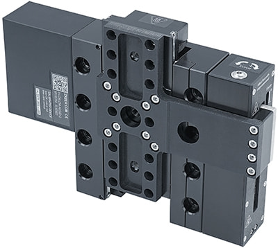
LDA-AEZ Series User's Manual
High precision vertical stages
Disclaimer
Zaber’s products are not intended for use in any critical medical, aviation, or military applications or situations where a product's use or failure could cause personal injury, death, or damage to property. Zaber disclaims any warranty of fitness for a particular purpose. The user of this product agrees to Zaber's general terms and conditions of sale.
Precautions
Zaber's autodetect peripheral axes are designed to be used effortlessly with Zaber's line of autodetect controllers. The LDA-AEZ includes onboard memory that allows Zaber's controllers to autodetect the model and set reasonable parameters. See the Protocol Manual for more information on how to modify the settings. Damage to the axis may result if the settings are not correct. To use your Zaber peripheral with a third-party controller, review the motor, sensor, and encoder specifications and pin-outs carefully.
Contamination could impact the performance of the LDA-AEZ stage. Avoid introduction of ferro-magnetic particles to the stage, and contact with, or contamination of, the encoder scale.
Important Precautions for Use
 Mounting and Maintenance Hazard! For operator safety, the LDA-AEZ should always be un-powered during all cleaning, maintenance, and stage or load mounting operations. A powered stage could exert high forces and move at high speeds very suddenly if accidentally given a move command.
 Strong Magnets! The LDA-AEZ stages contain strong magnets that could affect pacemaker function. Pacemaker users should stay at least 20 cm away from the stages. The magnets can also attract nearby magnetic objects.
Secure Stage Mounting Required! The LDA-AEZ stages can shake and vibrate during operation due to high inertia. The stages must always be securely mounted to a work surface during operation. See #Physical_Installation for information on stage mounting.
Back-driving Hazard! Linear motor stages require current to the motor coils to provide a force to maintain position and/or support a load. If power is removed the carriage may move suddenly or in an uncontrolled manner. The LDA-AEZ stage is not intended for load lifting operations due to the risk of uncontrolled motion if driver power is removed.
Collision Hazard! Provide a safe distance around the stage and its load to allow for unobstructed full travel movements between travel end-stop bumpers. Ensure that a positional overshoot or unexpected motion couldn't result in a collision hazard.
 Important: The LDA-AEZ stage should be homed immediately upon power-up.
Important: The LDA-AEZ is a servo device, meaning that its performance is dependent on proper tuning of the servo parameters for the given load. The use of incorrect servo parameters may reduce the device’s performance in operation. Incorrect tuning may also result in unstable operation, which can cause unexpected rapid motion of the device, leading to reduced device lifetime and user injury. When the operating load on the device is changed, the tuning parameters should be updated to match. For details see the servo tuning guidelines.
Noise Emissions
The A-weighted emission sound pressure level (SPL) of this device does not exceed 70 dB(A) during intended use.
Conventions used throughout this document
- Fixed width type indicates communication to and from a device. The
 symbol indicates a carriage return, which can be achieved by pressing enter when using a terminal program.
Device Overview
AutoDetect
Your LDA-AEZ peripheral is equipped with AutoDetect, a feature that allows a Zaber controller to automatically configure its settings for the peripheral when it is connected.
Important: The controller should always be powered down before disconnecting or connecting your LDA-AEZ peripheral.
To connect the peripheral to a controller:
- Power off the controller.
- Connect the LDA-AEZ peripheral.
- Power on the controller.
- The controller will activate the peripheral shortly after it is powered on.
See the Zaber controller user manual for more details on peripheral activation and control.
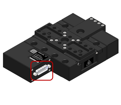
Connectors
Recommended controller(s) for your LDA-AEZ peripheral are provided in the product specifications. Zaber's controllers and peripherals are designed for ease of use when used together. Optimal settings for each peripheral are automatically detected by Zaber's controllers when the device is connected.
For reference, the pinout for the peripheral cable connectors is shown below:
Pinout for D-sub 26 Connectors (peripherals)
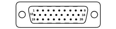
Male High Density D-sub26 Connector |
Pin | Description | Pin | Description |
|---|---|---|---|---|
| 1 | AutoDetect Clock | 14 | Motor Hall C | |
| 2 | AutoDetect Data | 15 | +5V | |
| 3 | N.C. | 16 | Ground | |
| 4 | N.C. | 17 | N.C. | |
| 5 | N.C. | 18 | Motor W | |
| 6 | Motor Over-Temperature | 19 | Differential Encoder A- | |
| 7 | Ground | 20 | Differential Encoder B- | |
| 8 | Motor V | 21 | Differential Encoder Index- | |
| 9 | Motor U | 22 | Motor Hall A | |
| 10 | Differential Encoder A+ | 23 | Motor Hall B | |
| 11 | Differential Encoder B+ | 24 | N.C. | |
| 12 | Differential Encoder Index+ | 25 | N.C. | |
| 13 | Differential Encoder Error | 26 | N.C. |
NOTE: All hall sensor signals (for limits or motor phase) are open collector and require a pull-up on the controller.
NOTE: All single-ended encoder inputs are non-isolated 5V TTL lines.
NOTE: All differential encoder signals are non-isolated, and must be terminated on the controller with 120 Ω. For -AE peripherals, these signals are sinusoidal with 1 V peak-to-peak differential levels and with the common mode between 1.5 V and 2.5 V.
Alternate Controllers
The LDA-AEZ can be controlled by other linear motor controllers with appropriate encoder input. We do not recommend using your own controller unless you are familiar with wiring and tuning third-party linear motor products. Damage to the device due to incorrect wiring is not covered by warranty.
Motors & Encoders
For motor and encoder information see the LDA-AEZ product page
Installation
The LDA-AEZ can be operated by connecting to the controller/s recommended in the product specifications. Please review the controller's user manual as well.
Physical Installation
Mounting and Maintenance Hazard! For operator safety, the LDA-AEZ should always be un-powered during all cleaning, maintenance, and stage or load mounting operations. A powered stage could exert high forces and move at high speeds very suddenly if accidentally given a move command.
Unpacking & Handling
LDA-AEZ stages are shipped with a red plastic travel lock designed to restrict motion of the stage during transport. This lock must be removed prior to mounting the stage.
-
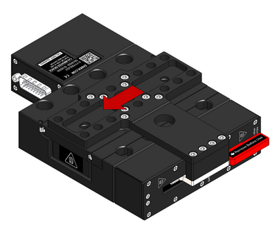
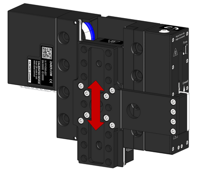
Compress the counterbalance by applying force to the carriage as shown while holding the base stationary. Up to 10N (2.2lb) of force may be required to compress the counterbalance.
-
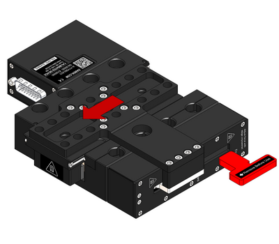
While compressing the counterbalance, remove the travel lock out the side. Retain this part for future use.
-
Slowly release the force applied to the stage. The counterbalance will push the carriage to the top end of travel.
Mounting
Tip: To obtain the best pitch, roll, yaw and straightness performance, mount the stage to a known flat, stiff surface. Our tests were performed on a granite surface plate, grade A flatness.
Stability Hazard! Ensure the stage is fastened to a secure surface before mounting a load on the carriage. Ensure loads are mounted securely to the carriage of the stage before operating.
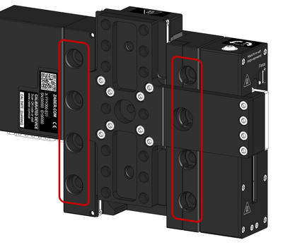
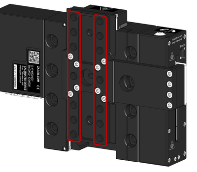
LDA-AEZ stages are designed to be secured using M6 socket cap screws, 30 mm or longer. It is recommended to use as many mounting holes as possible to maximize stiffness and straightness performance. It is not recommended to use less than 4 fasteners for mounting.
-
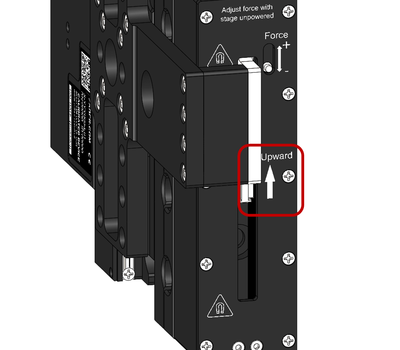
The stage must be mounted with a specific end facing upwards. The upwards direction is indicated by an arrow on the side of the counterbalance.
-
Mount the stage with M6 screws through the indicated mounting holes.
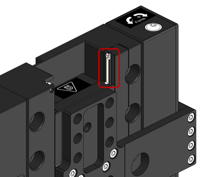
Counterbalance Adjustment
LDA-AEZ stages feature a passive adjustable magnetic counterbalance. The counterbalance force output should be adjusted to neutrally balance whatever payload weight is mounted to the stage. Proper adjustment of the counterbalance will ensure that the stage does not move unexpectedly if power is lost.
-
Remove power from the stage or send a driver disable command to disable the motor.
-
Mount the desired payload to the stage using the M6 mounting holes.
-
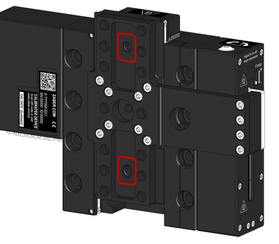
Optional: For precision alignment, payloads can be aligned to the stage using a pair of 6 mm dowel pins inserted into the indicated holes.
-
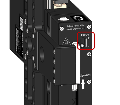
The counterbalance force is indicated on the side of the stage. It may be necessary to add extra payload mass to the stage if the counterbalance's minimum force is greater than the payload weight.
-
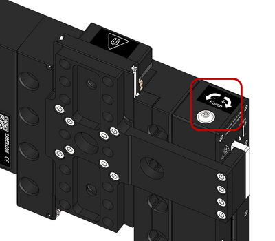
Adjust the counterbalance force by rotating the 2.5mm hex screw on top of the counterbalance. The screw will be easiest to adjust with the stage near it's topmost position. Adjust the force until the payload is neutrally balanced.
-
The adjustment screw may begin to unthread when decreasing the force. If the force indicator does not display minimum force, manually cycle the stage through it's travel range to decrease the counterbalance force.
-
With the payload neutrally balanced, power up the stage or send a driver enable command to re-enable the motor.
Servo Tuning
This peripheral is a closed-loop positioning servo system. It continuously monitors and corrects its position via the linear encoder. As with any servo system, the behaviour is dependent on the controller tuning. The LDA-AEZ, when paired with a compatible Zaber controller, such as an X-MCC series Universal Motor Controller, will be appropriately tuned out of the box with settings that are optimized for regular use under a light load. However, as with any closed-loop feedback system, the device performance is load-dependent, and conditions significantly outside of the intended operating range have the potential for reduced performance or instability. Thus, if operation with large or unconventional dynamic loads is desired, or if the application demands specific performance characteristics, it may be necessary to tune the servo parameters. This may be conveniently done by using Zaber Launcher's Servo Tuner App, or Zaber Motion Library's ServoTuner API. Additional settings that control the closed-loop behaviour of the product are described in the Zaber ASCII Protocol Manual. It is important to ensure that the chosen servo tuning parameters provide sufficient stability margin for the system that is being driven.
Tip: Because servo devices continuously monitor and correct position, it is necessary to specify how accurate and stable the final position must be at the end of the movement. Criteria required for the controller to report IDLE status after movement are specified using the cloop.settle.tolerance and cloop.settle.period settings. For applications requiring utmost precision, you may want to specify a smaller tolerance and longer period. Note that there is an inverse relationship between the value of cloop.settle.tolerance and real-life observed settling time, and the controller may never report IDLE status if the tolerance is too small.
The following diagram illustrates some of the possible issues with trajectory-following performance due to non-optimal servo tuning parameters. When the servo parameters are well tuned, the system will follow the planned trajectory (red line) with minimum deviation, as long as the chosen trajectory is achievable. For the poorly chosen servo parameters in the example below, there is significant lag and oscillation compared to the planned trajectory.

Tip: The position servo controller in Zaber products tracks a pre-planned motion trajectory. For this reason, it is sometimes necessary to modify the trajectory planning settings such as accel or maxspeed as well as the servo tuning parameters in order to obtain optimal positioning performance.
Lubrication and Cleaning
LDA-AEZ devices use cross roller bearing linear guides to support and guide the stage top of the device. These linear guides require lubrication in order to achieve the longest possible lifetime at the highest possible performance. For operation in clean environments, it is recommended to lubricate the linear guides annually or every 500km, whichever comes first. For applications in dirty environments or applications with extremely high duty cycles, more frequent inspection and lubrication is recommended. For longest lubrication intervals, we recommend lubricating guides with Kluberplex BEM 34-132 grease. All guides come pre-lubricated and are ready to go out of the box.
If LDA-AEZ devices are used in applications where only a small portion of the travel range is used, it is recommended to occasionally drive the stage throughout its full travel range to maintain an even lubrication film over the entire guide surface.
-
Remove power to the device before attempting to lubricate.
-
1. Manually move the stage to a travel limit to expose the linear guides.
2. Using a lint free cloth, wipe away any old grease and debris on the v-channels of the guides. Wipe towards the outside of the stage so debris is not pushed into the roller bearings.
3. Apply a thin strip of lubricant over the entire exposed length of the v-channels with a syringe.
4. Manually move the stage to the opposite travel limit and repeat steps 2 and 3 on the opposite side. -
Manually cycle the stage throughout its full travel range a few times to evenly distribute the lubricant. Wipe away any excess lubricant.
Trajectory Control and Behaviour
This section describes the behaviour of the axis trajectory when a movement command is issued.
Software Position Limits
The travel range of the axis is limited by the Minimum Position and Maximum Position settings. The factory settings for the axis are configured to match the physical travel range. If a customized range is desired, it can be changed by configuring the limit.min and limit.max settings to appropriate values. For the Current Position, query pos.
- Minimum Position
- When the Current Position is less than the Minimum Position value, the axis cannot move in the negative direction.
- Maximum Position
- When the Current Position is greater than the Maximum Position value, the axis cannot move in the positive direction.
Movement Speed
The movement speed of the axis depends on axis status and various speed settings. If the axis has not been initialized by the home command or by moving towards the home end of the axis, movement speed will be constrained to fail-safe values. The home status of the axis can be determined by reading the limit.home.triggered setting.
Movement speed of the axis is specified below:
- move vel
- The axis will move at the specified speed regardless of home status.
- Knob movement in Velocity Mode
- The axis will move at the specified speed regardless of home status.
- The speed is specified by the knob.speedprofile and knob.maxspeed settings.
- Other movement commands - when the axis has not been homed
- The axis will move at the slower of the maxspeed and limit.approach.maxspeed settings.
- Other movement commands - when the axis has been homed
- The axis will move at the speed specified by the maxspeed setting.
Warranty and Repair
For Zaber's policies on warranty and repair, please refer to the Ordering Policies.
Standard products
Standard products are any part numbers that do not contain the suffix ENG followed by a 4 digit number. Most, but not all, standard products are listed for sale on our website. All standard Zaber products are backed by a one-month satisfaction guarantee. If you are not satisfied with your purchase, we will refund your payment minus any shipping charges. Goods must be in brand new saleable condition with no marks. Zaber products are guaranteed for one year. During this period Zaber will repair any products with faults due to manufacturing defects, free of charge.
Custom products
Custom products are any part numbers containing the suffix ENG followed by a 4 digit number. Each of these products has been designed for a custom application for a particular customer. Custom products are guaranteed for one year, unless explicitly stated otherwise. During this period Zaber will repair any products with faults due to manufacturing defects, free of charge.
How to return products
Customers with devices in need of return or repair should contact Zaber to obtain an RMA form which must be filled out and sent back to us to receive an RMA number. The RMA form contains instructions for packing and returning the device. The specified RMA number must be included on the shipment to ensure timely processing.
Email Updates
If you would like to receive our periodic email newsletter including product updates and promotions.
Contact Information
Contact Zaber Technologies Inc by any of the following methods:
| Phone | 1-604-569-3780 (direct) 1-888-276-8033 (toll free in North America) |
|---|---|
| Fax | 1-604-648-8033 |
| #2 - 605 West Kent Ave. N., Vancouver, British Columbia, Canada, V6P 6T7 | |
| Web | www.zaber.com |
| Please visit our website for up to date email contact information. |
The original instructions for this product are available at https://www.zaber.com/manuals/LDA-AEZ.
Appendix A: Default Settings
Please see the Zaber Support Page for default settings for this device.
Product Drawing
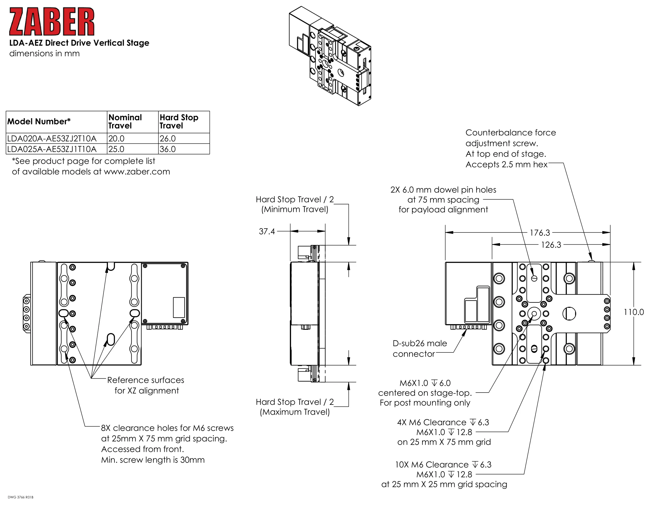
Specifications
| Specification | Value | Alternate Unit |
|---|---|---|
| Built-in Controller | No | |
| Recommended Controller | MCC (48 V) Recommended | |
| AutoDetect | Yes | |
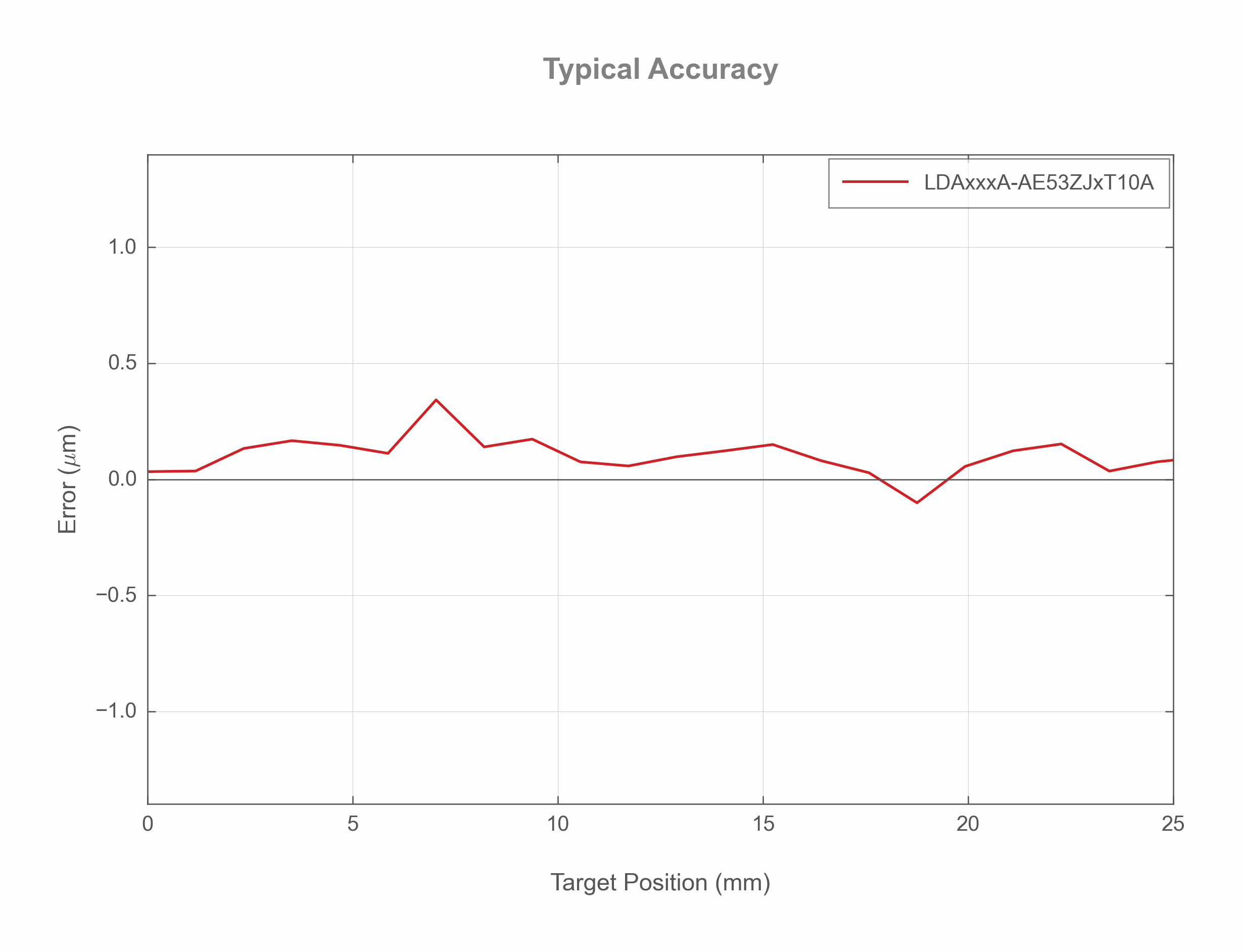
| Accuracy (unidirectional) | 1.5 µm | 0.000059" |
| Repeatability | < 0.2 µm | < 0.000008" |
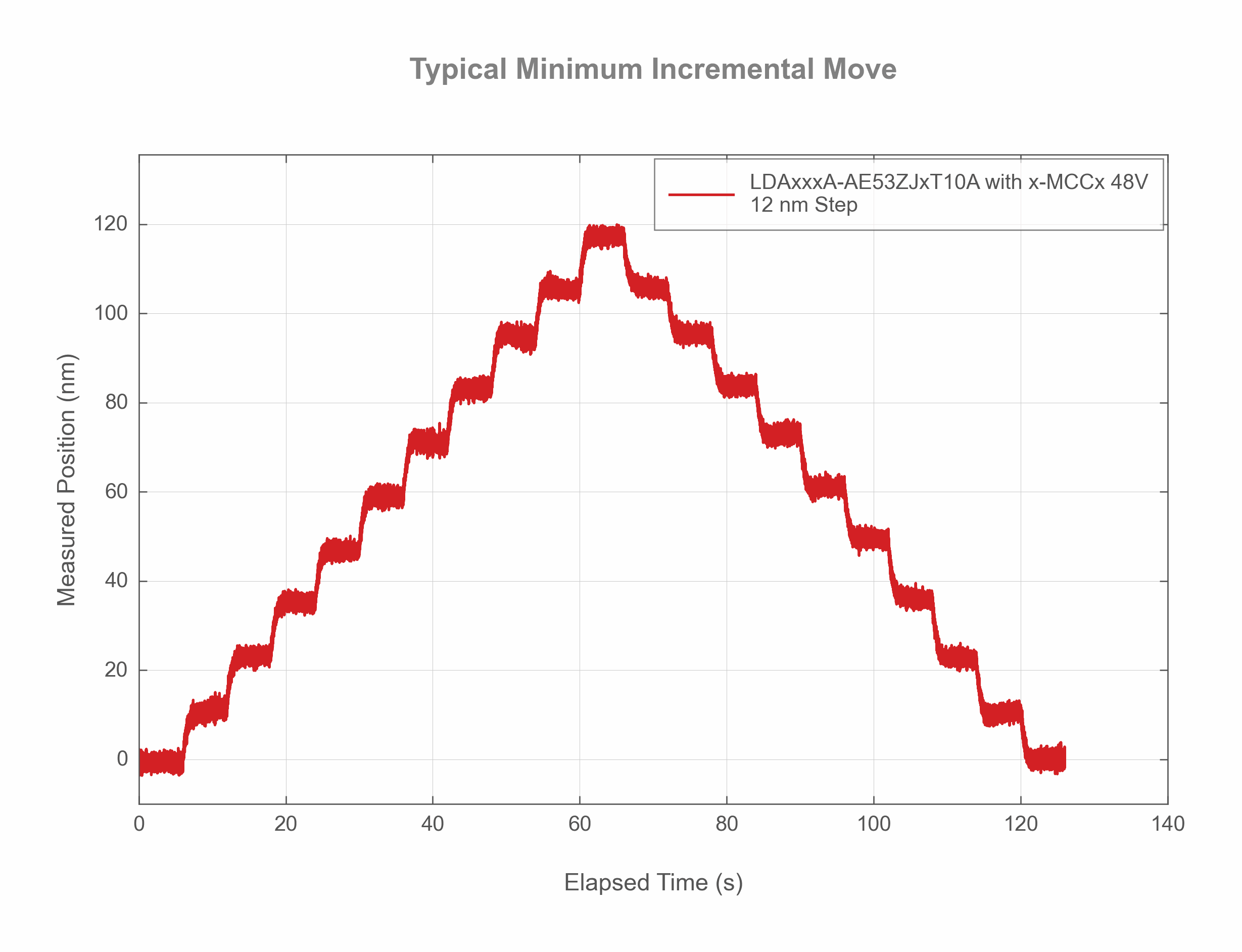
| Minimum Incremental Move | 12 nm | |
| Minimum Speed | 0.61 nm/s | |
| Speed Resolution | 0.61 nm/s | |
| Encoder Type | Linear analog encoder | |
| Encoder Count Size | 1 nm | |
| Peak Thrust | 16 N | 3.6 lb |
| Maximum Continuous Thrust | 6 N | 1.3 lb |
| Maximum Moment (Pitch) | 5 N⋅m | 3.7 lb⋅ft |
| Maximum Moment (Roll) | 5 N⋅m | 3.7 lb⋅ft |
| Maximum Moment (Yaw) | 5 N⋅m | 3.7 lb⋅ft |
| Straightness of Travel | < 4 µm | < 0.000157" |
| Pitch | 0.006° | 0.105 mrad |
| Roll | 0.005° | 0.087 mrad |
| Yaw | 0.005° | 0.087 mrad |
| Stiffness (Pitch) | 500 N⋅m/° | 35 µrad/N⋅m |
| Stiffness (Roll) | 500 N⋅m/° | 35 µrad/N⋅m |
| Stiffness (Yaw) | 400 N⋅m/° | 44 µrad/N⋅m |
| Counterbalance Type | Adjustable Magnetic | |
| Motor Type | Moving Magnet Track Linear Motor (3 phase) | |
| Motor Rated Current | 1800 mA | |
| Motor Winding Resistance | 2.3 ohms line-to-line | |
| Motor Winding Inductance | 0.09 mH line-to-line | |
| Motor Connection | D-sub 26 | |
| Force Constant | 3.7 N/A | 0.8 lbs/A |
| Guide Type | Crossed-Roller Bearing | |
| Limit or Home Sensing | Optical Index Mark | |
| Axes of Motion | 1 | |
| Mounting Interface | M6 threaded holes | |
| Operating Temperature Range | 0 to 50 °C | |
| CE Compliant | Yes | |
| Vacuum Compatible | No | |
| Weight | 1.26 kg | 2.778 lb |
Comparison
| Part Number | Travel Range | Maximum Acceleration | Maximum Speed | Counterbalance Payload Range |
|---|---|---|---|---|
| LDA020A-AE53ZJ2T10A | 20 mm (0.787") | 10 m/s2 (1.02 g) | 400 mm/s (15.748"/s) | 8-16 N (1.8-3.6 lb) |
| LDA025A-AE53ZJ1T10A | 25 mm (0.984") | 25 m/s2 (2.55 g) | 700 mm/s (27.559"/s) | 0-7 N (0.0-1.6 lb) |
Charts and Notes
Product Change Notices
Click here to view the current product change notices and subscribe to future change notifications.