Piezo or Linear Motor? An Updated Selection Guide for Nanometer-Scale Precision
By Adlin Alwyn, Applications Engineering Team
Published on Apr. 30, 2026
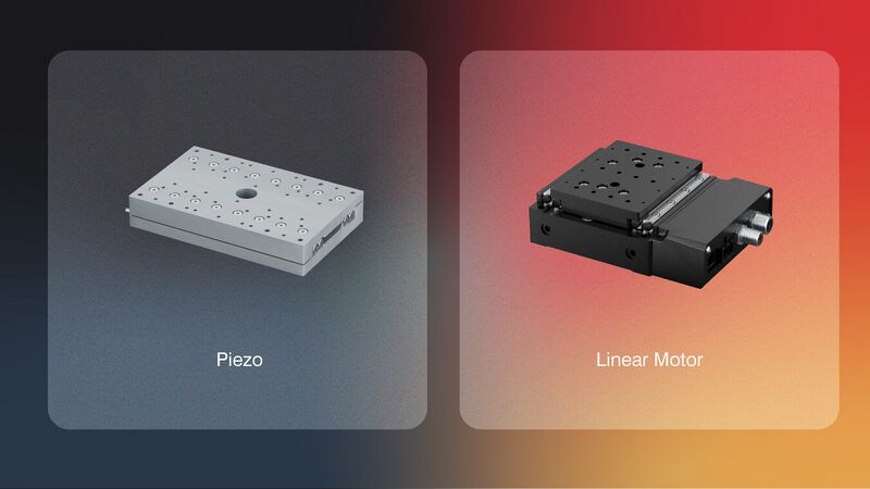
Recent advancements in compact drive electronics and motor technology have brought the capabilities of piezoelectric and linear motor stages into closer overlap than ever before. While it was once assumed that nanometer-level precision required a piezo drive, modern direct-drive linear motors can now achieve that level across significantly larger travel ranges. As the cost of a linear motor system can be one-third that of a piezo alternative, we’ve written this selection guide to help you understand the performance overlap and optimize your budget. We also provide examples of when to combine these two technologies for maximizing system performance and cost efficiency.
Selection Guide: Balancing Performance Trade-offs
Choosing between piezoelectric and linear motor technology is rarely a straightforward decision. The following categories highlight where each technology excels and where the modern linear motor has expanded its reach. For a side-by-side comparison of additional specifications, including speed, thrust, and estimated pricing, please refer to the Performance Benchmarks table in Appendix A.
1. Minimum Incremental Move vs. Travel Range
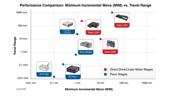
While both technologies can achieve nanometer-scale movement, the price-to-performance ratio shifts dramatically once system requirements exceed that threshold.
- Sub-Nanometer Precision (< 1 nm MIM): Piezo-flexure stages (blue icons in the graph above) remain the primary solution for increments below 1 nm. As the graph illustrates, these stages are typically restricted to travel ranges below 3 mm.
- Nanometer Precision (4 nm – 25 nm MIM): This range is where direct-drive linear motors (red icons) provide the most significant return on investment, often at one-third the cost of piezo systems. In this range, linear motors provide orders of magnitude more travel without sacrificing precision. For example:
While stick-slip piezo stages can theoretically reach 500+ mm, the cost per millimetre can be significantly higher than the linear motor alternatives, making the linear motor the economical choice.
2. Throughput: Motion Profile and Duty Cycle
A system's throughput is often defined by how fast it moves, how quickly it settles, and how long it can run without maintenance.
- < 5 ms Settle Time: For fast stop-and-go motion over microscopic distances, piezo-flexure stages are the standard. They can move and settle fast enough to allow a 100-slice 3D volume to be captured in under a second.
- < 15 ms Settle Time: Modern linear motors now offer the acceleration and settling speeds necessary to compete with piezo stages in step-and-scan applications, but without the sub-millimetre travel limits.
- Example: The Zaber DMA moving a 250 g payload with optimized servo tuning can complete a 250 nm move and settle within 15 nm of the target within 15 ms.
- 100% Duty Cycle: If an application requires high-speed movement 24/7, linear motors and piezo-flexure stages are the ideal choice. Unlike piezo stick-slip motors that rely on friction and are prone to wear, linear motors and piezo-flexure stages utilize a non-contact drive, resulting in a longer operational lifetime.
3. Operating Environment: Noise and Other Conditions
- Silent to Quiet Operation: Piezo-flexure stages are silent during operation. Piezo stick-slip stages can often produce a high-pitched chirp or whine during motion, while linear motors produce a quiet, low-frequency hum due to their bearings, which is generally less intrusive in quiet laboratory settings.
- UHV and Cryogenic Compatibility: Piezo stages remain the best solution for Ultra-High Vacuum (10^-9 Torr) and Cryogenic applications.
4. Physical Footprint: Stage vs. System Size
In many applications, the total workspace volume, i.e., the space taken up by both the stage and other components, is a key consideration.
- Miniature Workspace (Stage Only): Piezo stages are the preferred choice when the physical mounting area is extremely limited. A stick-slip piezo stage with 21 mm of travel can be as small as 32 x 32 x 11 mm.
- The Controller Trade-off: While the stage is miniature, piezo systems require separate external controllers that are often substantially larger than the stage itself.
- Integrated Control (Reduced System Volume): Linear motor stages are typically larger than piezo stages but often feature integrated controllers. This eliminates the need for external drive electronics and messy cabling.
- Example: The Zaber DMA size is 100 x 77 x 30.5 mm with a built-in controller.
5. Load Capacity: Payload vs. Travel
- 0.1 – 2 kg (Light Payloads): Piezoelectric and linear motor stages are both capable of moving light payloads like objective lenses, pipettes, miniature sensors or lasers.
- 10 – 20+ kg (Heavy Industrial Payloads): For heavy tool heads moving across large worktables, direct-drive linear motors offer the most practical balance of price and travel.
- Example: Zaber’s X-LDQ-AE can move 20 kg over 1 meter.
Combining Technologies: The Cost-Effective Approach
When an application requires both a large workspace and sub-nanometer resolution, users often combine these technologies into a single system. The following examples demonstrate how to utilize different drive types within a single system to achieve high-end performance while maintaining cost-efficiency.
1. Coarse and Fine Positioning (XY Scanning)
The Application: Coarse and fine positioning of an XY scanning system is ideal for semiconductor wafer inspection or micro-electronics PCB inspection. These workflows typically involve scanning a substrate or wafer containing multiple chips.
The Setup: A linear motor stage moves the entire substrate to bring each individual chip into the camera’s general focus area, a task that might require 4-25 nm incremental moves depending on chip feature sizes. Once the chip is in position, the piezo stage takes over to shift the chip in 1 nm increments to inspect specific microscopic features.
In this example, the coarse positioning of the substrate in the X-axis is achieved by using the Zaber X-LDM. A piezoelectric stage (like the SmarAct CLS-5282) is mounted on top of the X-LDM carriage using a custom adapter plate to handle the fine positioning of the substrate in the Y-axis. This configuration allows users to use cost-effective linear motors to position the chip to the camera, and then leverage the piezo's finer precision for the actual inspection of chip details.
2. High-Speed 3D Imaging (Z-stacking with XY Scanning)
The Application: XYZ stage configurations are commonly used for gene sequence screening or laser profiling. These processes employ Z-stacking, which captures a series of images at different focal depths at hundreds of different locations across a 96-well plate or glass slide.
The Setup: In this example, the sample stays in a fixed position while the motion system moves the camera assembly horizontally in XY to each location and then moves the camera vertically to capture images at varying depths
Two Zaber LDA linear motor stages are used in an XY configuration to move the camera. A high-precision Zaber DMA is mounted vertically to the Y carriage to handle focusing. Historically, Z-stacking required piezo-flexure stages for speed, which limited vertical travel to under 5 mm. By using the DMA, users can achieve a 10 mm vertical range with piezo-like settling times, all within a single, unified control architecture.
Conclusion
Advances in technology continue to increase the overlap in performance between linear motor and piezoelectric stages. Whether selecting a single drive or combining technologies, contact our Applications Engineering team to help you navigate the trade-offs to find the most effective solution.
Appendix A: Performance Benchmarks: Comparing Precision, Travel, and Cost
The following table provides a representative comparison of precision, travel, and cost across the motion control industry. To ensure an objective look at the current landscape, these numbers were compiled by analyzing the published specifications of several leading manufacturers in the piezoelectric and linear motor sectors.
While this data reflects standard performance across well-known platforms, it is not intended to be an exhaustive list of all specialized or custom drive variants. All costs are estimated based on a complete system, including the necessary controller and power supply.
| Feature | Piezo (Flexure) | Piezo (Stick-Slip) | Linear Motor |
|---|---|---|---|
| Travel Range | 0.1 - 3 mm | 10 - 650 mm | 10 - 1000 mm |
| Min. Move (MIM) | 0.05 - 1 nm | 1 - 15 nm | 4 - 25 nm |
| Speed | 10 - 500 mm/s | 10 - 100 mm/s | 800 - 1500 mm/s |
| Cost* | $5,500 - $25,000 | $12,000 - $47,000 | $4,000 - $15,000 |
| Peak Thrust | 5 - 50 N | 5 - 50 N | 10 - 100 N |
| Duty Cycle | 100% | 50–80% | 100% |
| Voltage | 50 - 500 V | 100 - 150 V | 24 - 48 V |
| Power-Off State | Returns to start | Self-locks | Coasts freely |
| Backdriveable? | No | No | Yes |
| Audible Noise | Silent | High Chirp/Whine | Quiet hum |
| Maintenance | Infinite cycles, unless the ceramic is cracked by shock or electrical breakdown. Replacement parts are expensive. | Infinite cycles. Bearing failure is possible, but can be mitigated by re-lubrication. Replacement parts can be expensive. | Infinite cycles. Bearing failure is possible, but can be mitigated by re-lubrication. Replacement parts are low-cost when compared to the other two. |
Table 1: Performance Benchmarks for Precision Motion Stages. *Cost estimates include the necessary controller and power supply. Note that linear motors provide a significantly lower cost-per-millimeter of travel in the 10-25 nm precision range.