MSR Series User's Manual
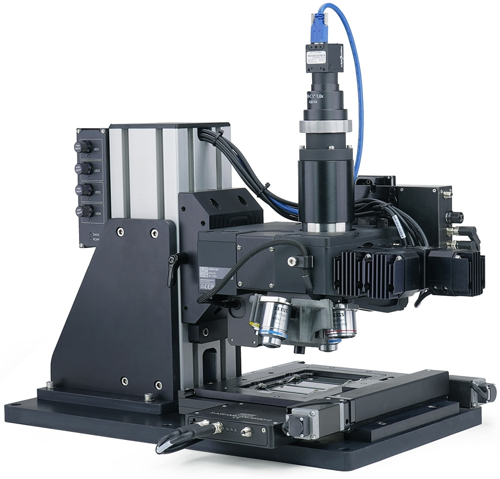
Nucleus® MSR upright fluorescence microscopes
Disclaimer
Zaber’s products are not intended for use in any critical medical, aviation, or military applications or situations where a product's use or failure could cause personal injury, death, or damage to property. Zaber disclaims any warranty of fitness for a particular purpose. The user of this product agrees to Zaber's general terms and conditions of sale.
Precautions
 UV Light Hazard! The MLR illuminator contains a high-power UVA LED. Do not look directly into the beam of light or expose skin.
Heavy! Completely assembled Nucleus microscopes can weigh more than 18 kg/40 lb. Exercise caution when lifting/moving larger assemblies.
 Important: Many Components/Assemblies within the microscope must remain dust and fingerprint-free inside to prevent issues with image quality. Use gloves when handling optics (mirrors, lens, prisms, filters). Use air duster cannisters or bulb blowers to remove dust or lint from optics where necessary. Retain covers and caps for re-use to cover openings to microscope components.
Assembly
Nucleus modular microscopes require some assembly and set-up upon arrival. Zaber microscopes can be disassembled, packed, and transported for use in new locations, or re-configured with additional modules to suit new applications. To set up a Zaber Nucleus upright microscope, complete the following steps. Contact Zaber Customer Support at any time for clarification or additional information.
Mounting the MTR support column on a Zaber upright Microscope
This process details the installation the MTR and MKR core modules with XY stage to the build an upright microscope. The modular nature of Zaber’s microscopy platform means that different configurations are possible. In this example an X-ASR100 XY stage and an AP260 base are shown.
-
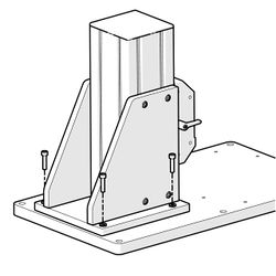
Screw the MTR upright column to the base plate. Note: Systems using the MTR300A may use the optional AP260 base plate (pictured here). Systems using the MTR300D support column will require a larger and stiffer base plate. The specific dimensional and stiffness requirements will depend on the XY stage selected, and imaging performance requirements.
-
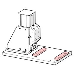
Mount the required stage supports to the base plate. AP110 (highlighted) is pictured, though the specific stage supports will be XY stage dependent.
-
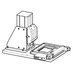
Mount the XY stage. X-ASR100 pictured. The mounting procedure for the stage will vary depending on the specific stage mode. Please refer to the documentation for your specific stage.
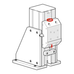
-
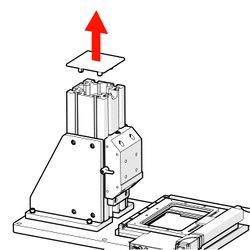
Remove the top cap from the MTR support column.
-
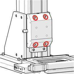
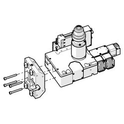
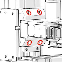
Loosen the screws holding the MKR mounting block to the MTR upright column by one turn only.
-
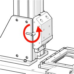
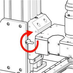
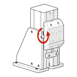
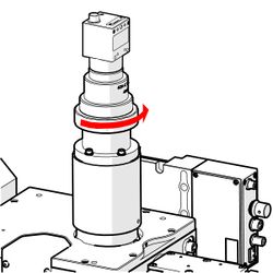
Rotate the clamp lever counterclockwise to loosen the mounting block clamp.
-
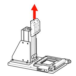
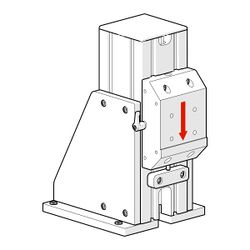
Slide the MKR mounting block up and off the MTR upright column.
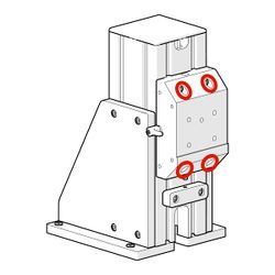
-
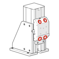
For the MTR300A : Mount the microscope core module onto the MKR Mounting block with the four long M6 screws provided.
-
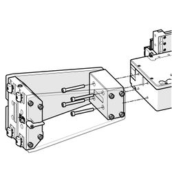
For the MTR300D : Mount the microscope core module onto the MKR Mounting block extension with the four long M6 screws provided.
-
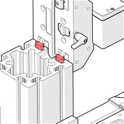
Line the T-nuts on the MKR mounting block up with the slots in the MTR support column.
-
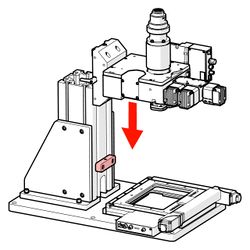
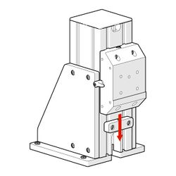
Slowly slide the MKR microscope core and mounting block assembly down onto the MTR support column until it reaches the safety stop.
-
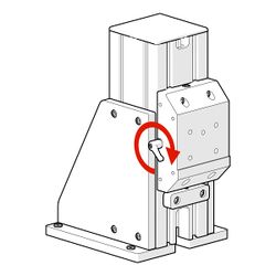
Rotate the clamp knob clockwise to tighten the MKR mounting block clamp.
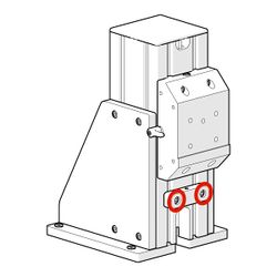
-
Tighten the mounting block screws.
-
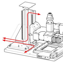
Feed the power and data cables though the cable ports in the MTR vertical column.
-
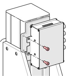
Screw the X-LCA4 controller to the AP261 mounting bracket.
-
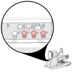
Connect the power cables from the MLR3 Illuminator channels to the X-LCA4 lighting controller. The X-LCA4 comes pre-configured for the LED power cables to be connected in ascending order of wavelength starting with the LED1 connector. The channels will appear in the Zaber Launcher App in the order they are connected to the X-LCA4.
-
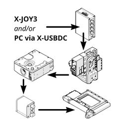
Connect the X-DC cables to the "Prev" and "Next" ports on each module. To match the default joystick control configuration, the device order should be: X-JOY3, X-LCA4, X-LDA, X-FCR06, X-MOR4-E (optional), X-ASR (Your XY stage).
-
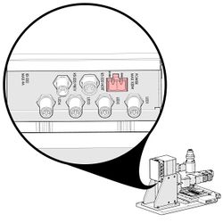
Connect the power supply cable to the power port on the X-LCA4 lighting controller.
Adjusting the height of the microscope core.
The MTR module is shipped with the MKR safety stop installed at a pre-set height. This position is easily adjusted as required. For clarity, the MTR300A with no attached MKR module is shown.
-
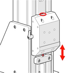
Loosen the screws securing the safety stop
-
Lower the safety stop by the desired distance. The MTR module includes a fine positioning function (Step 4), so positioning the stop several mm lower than anticipated may be helpful.
-
Tighten the safety stop screws.
-
Extend the fine positioning screw to provide room for both positive and negative position adjustment.
-
Loosen the screws holding the MKR mounting block to the MTR upright column by one turn only.
-
While supporting any load such as an MKR microscope core and associated module attached to the mounting block, loosen the clamp knob.
-
Gently lower the mounting block until the fine positioning screw makes contact with the safety stop.
-
Use the fine positioning screw to make any small vertical position adjustments required.
-
Once the system is in its desired position, tighten the clamp knob just enough to eliminate any slop in the mounting block.
-
Tighten the main mounting block retention screws.
Installing an Objective
-
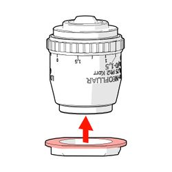
Screw the magnetic adapter ring. The wide flange should face towards the sample side of the objective.
-

-
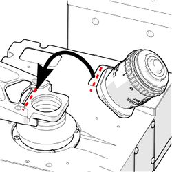
For single objective systems: line a flat edge on the adapter ring up with the flat edge on the magnetic adapter ring. Load the objective into objective mount on the AB170.
-
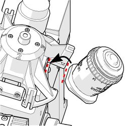
For the X-MOR4 objective changer: line a flat edge on the adapter ring up with the flat edge on the magnetic adapter ring. Load the objective into objective pocket in the carousel. Repeat for the next objectives.
Installing a Camera
-
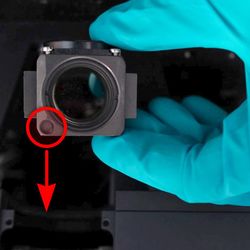
Remove the dust cap off the camera C-Mount threads. Screw the camera securely onto the C-Mount threads.
-
Connect the power/data cables.
-
Ensure any locking screws are tight.
-

If the camera is not aligned with the axes of motion, image stitching issues may result. To align the camera, first loosen the C-Mount lock ring.
-
While viewing the camera image, rotate the camera so it is aligned with the pixel rows and columns.
-
Tighten the lock ring to secure the camera.
Installing Filter Cubes
-
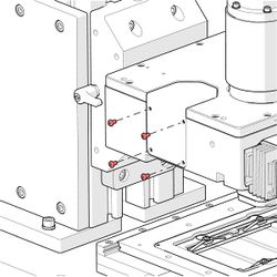
Remove the four screws on the filter cube turret door.
-
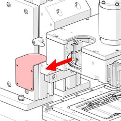
Manually rotate the filter cube turret to a free position if required.
-
Insert the filter cube (sold separately), ensuring the alignment mark is on the bottom side of the filter cube. Gloves are recommended when handling optical components to avoid marking surfaces with fingerprints.
-
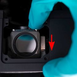
Push down, then forward until the filter “clicks” into place. Repeat for each additional filter cube. Replace the filter cube turret door.
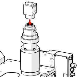
Installing a 3mm Liquid Light Guide Coupled Illuminator
-
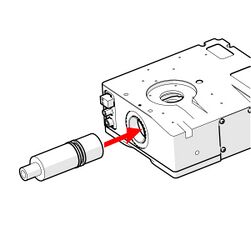
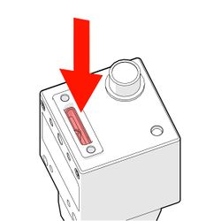
Insert the MLG3A light guide coupler into the illuminator port on the X-FCR06 module until it reaches the stop position.
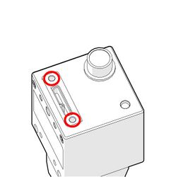
-
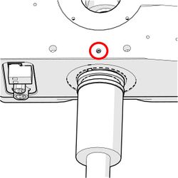
Tighten the retaining screw on the X-FCR06
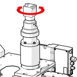
-
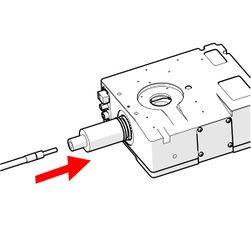
Insert the uniquid light guide into the MLG3A.
-
Tighten the light guide retaining screw on the MLG3A.
Connecting a Nucleus Microscope to a PC
-
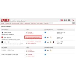
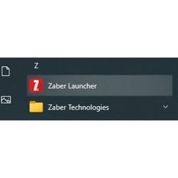
Go to https://www.zaber.com/software. Follow the links to download Zaber Launcher.
-

The Zaber Launcher download link will open a new page. Download the appropriate version for your operating system.
-
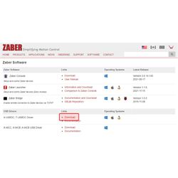
From the Zaber software page, follow the links for the X-USBDC driver download.
-
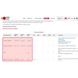
The driver download link will take you to an external page. Select the version of the drivers that matches your operating system, download and install it.
-
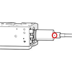
Plug the X-USBDC USB adapter into your computer. Connect locking end of the X-USBDC adapter to the right-hand locking connector on the X-JOY3 joystick controller. Launch the Zaber Launcher application.
-
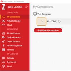
On the My Connections screen click ˃ to expand the device list. Zaber Launcher requires an internet connection when it is first connected with new devices. This enables it to automatically download the most up to date version of the device settings to ensure the best possible performance of your devices.
-
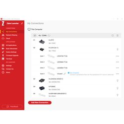
All the components of your Microscope should be listed in the following order: X-JOY3, X-LCA4, X-LDA, X-FCR, X-MOR4-E (optional), X-ASR or X-ADR. The X-ASR, X-ADR, and X-LCA4 LED channel icons are currently placeholder graphics.
-
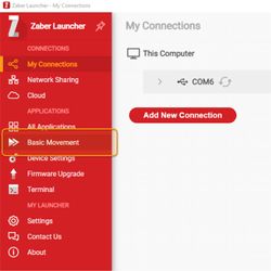
Select the "Basic Movement" tab from the red side bar
-
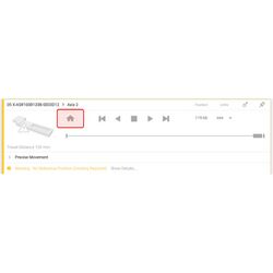
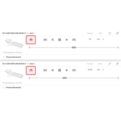
Click the Home button for each device with a yellow frame and a "No Reference Position" flag. All devices must be homed to calibrate their reference positions before their full range of motion and speed is available.
-
To set up μManager for automated image acquisition, follow the detailed μManager setup instructions.
Troubleshooting Assembly Issues
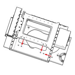
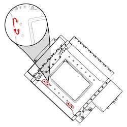
Mounting an X-ASR stage without an X-JOY3
To mount the ASR stage without an X-JOY3 controller, the stage must be moved using the Zaber launcher or Zaber console (legacy) desktop software.
-
Follow the instruction for connecting an MVR to your PC. Open the Zaber Launcher application. Home both axes of the X-ASR stage.
-
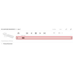
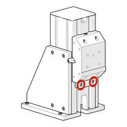
Use the position slider to move the lower axis and expose the mounting screw holes.
Micro-Manager Software Setup
Micro-Manager is a free, open-source software package that provides an easy-to-use interface for microscope automation. It supports a range of microscopes, cameras, and motion control devices, and works with ImageJ image processing software. All the motorized Zaber microscope modules can be controlled through Micro-Manager.
Zaber Console is the recommended software for testing troubleshooting and adjusting settings on the motorized microscope modules. Before starting the Micro-Manager setup procedure, we recommend installing Zaber Console and checking that all the devices are detected and operating properly.
Download and Install Camera Drivers
Download and install the driver software for the camera you are using as detailed below.
CC01 (FLIR BFLY-U3-23S6M-C)
Download and install FLIR (formerly Point Grey) Flycap driver:
- Download version 2.10.3.266 of the FlyCapture software here
- Install the SDK
- Choose "Complete" setup type
- Check “I will use USB cameras”
- Check “Register direct show dlls”
- Copy libiomp5md.dll and FlyCapture2_v100.dll files (from the bin or bin64 directory in the FlyCap2 directory) to the Micro-Manager root directory (default: C:\Program Files\Micro-Manager)
- Visit The Point Grey Research Micro-Manager device adaptor page for various notes on camera setup and use
FLIR Blackfly S and other Spinnaker Cameras
Download and install FLIR (Point Grey) Spinnaker drivers for Micro-Manager:
- Visit the Micro-Manager Spinnaker device adapter page and follow the instructions to download and install the device adapter.
Install Micro-Manager
Download the latest nightly build of Micro-Manager 2.0 gamma here. Install following the on-screen installation instructions.
Configure Micro-Manager
- Make sure the camera and all Zaber devices are connected and powered on. The camera and the daisy chain of Zaber devices will need to be plugged into separate USB ports.
- Open Zaber Console and check the device numbers of all devices. They should be:
- X-JOY3
- X-LCA4
- X-LDA025A-AE53D12
- X-FCR06C
- X-ASR or X-ADR XY Stage
- Renumber all devices if necessary
- Make a note of the COM port the Zaber devices are connected to.
- Close Zaber Console
- Home the X-LDA focus stage by pressing and holding button 1 on the X-JOY joystick. The focus stage must be homed like this (or through Zaber Console) after each time it is powered up.
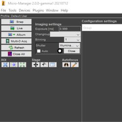
- Open Micro-Manager. On the startup screen, use the dropdown menu to select “none” for Hardware Configuration File.
- Open Hardware Configuration Wizard (Devices>Hardware Configuration Wizard)
- Select Create new configuration. Click Next.
- Add the camera:
- For CC01 (FLIR BFLY-U3-23S6M-C):
- Expand Point Grey folder and select Blackfly BFLY-U3-23S6M_SN: Point Grey Camera
- Click Add… and then OK
- For CC01 (FLIR BFLY-U3-23S6M-C):
- Add the X-LCA4 illuminator:
- Expand the Zaber folder
- Click on Illuminator: Zaber Illuminator and click Add…
- Enter the following values:
- Controller Device Number: 2
- Port: COM port the Zaber devices are connected to
- AnswerTimeout: 500
- BaudRate: 115200
- DataBits: 8
- DelayBetweenCharsMs: 0
- Fast USB to Serial: Off
- Handshaking: Off
- Parity: None
- StopBits: 1
- Verbose: 1
- Click OK
- Add the X-ASR or X-ADR series XY stage:
- In the Zaber folder, click on XYStage: Zaber XY Stage and click Add…
- Enter the following values:
- Axis Number (X Axis): 2
- Axis Number (Y Axis): 1
- Controller Device Number: 5
- Controller Device Number (Y Axis): leave blank
- Linear Motion Per Motor Rev (X Axis) [mm]: 2.0000 (X-ASR series), 1.0000 (X-ADR series)
- Linear Motion Per Motor Rev (Y Axis) [mm]: 2.0000 (X-ASR series), 1.0000 (X-ADR series)
- Motor Steps Per Rev (X Axis): 200 (X-ASR series), 1,000,000 (X-ADR series)
- Motor Steps Per Rev (Y Axis): 200 (X-ASR series), 1,000,000 (X-ADR series)
- Port: COM port the Zaber devices are connected to
- Communications port settings are the same for all Zaber devices
- Click OK
- Add the X-LDA025A-AE53D12 focus stage:
- In the Zaber folder, click on Stage: Zaber Stage and click Add…
- Enter the following values:
- Axis Number: 1
- Controller Device Number: 3
- Linear Motion Per Motor Rev [mm]: 1.0000
- Motor Steps Per Rev: 1,000,000
- Port: COM port the Zaber devices are connected to
- Communications port settings are the same for all Zaber devices
- Click OK
- Add the X-FCR06C filter cube turret:
- In the Zaber folder, click on FilterCubeTurret: Zaber Filter Cube Turret and click Add...
- Enter the following values:
- Controller Device Number: 4
- Port: COM port the Zaber devices are connected to
- Communications port settings are the same for all Zaber devices
- Click OK
- Click Next
- Select the default devices:
- Default Camera: The camera you setup in previous steps
- Default Shutter: Illuminator
- Default Focus Stage: Stage
- Select Stage focus direction: Positive Towards Sample
- Select FilterCubeTurret delay: 0
- Enter labels for Filter Cube Turret Positions or leave default labels (Filter Cube 0, Filter Cube 1, etc…)
- Choose a name for the configuration
- Click Finish
- Create Preset Groups as desired. Some suggested groups are:
- Groups for each individual LED channel. These will let you know at a glance which LEDs are running and at what intensity. They will also let you easily change LED intensity and turn individual channels on and off.
- Click the + sign next to Group
- From the list of properties, select Illuminator-Lamp 1 intensity
- Enter “LED 1” or another appropriate name for the channel
- Click OK
- Create similar groups in the same way for the other illuminator channels
- "Channels" group to synchronize the illuminator channel with the active filter cube
- Click the + sign next to Group
- From the list of properties, select the following:
- Illuminator-Lamp 1 intensity
- Illuminator-Lamp 2 intensity
- Illuminator-Lamp 3 intensity
- Illuminator-Lamp 4 intensity (if lamp 4 is in use)
- FilterCubeTurret-Label
- Any other properties you want to link to the channel presets. It can sometimes be useful to add camera gain (if available)
- Enter "Channels" or another appropriate name for the group
- Click OK
- Create presets for the different fluorescence channels:
- Click the + sign next to Preset
- Enter a name for the preset (DAPI, GFP, Cy3, etc…)
- Select the filter cube to be used for this channel and set the intensity of the illumination channel(s) to be used
- Click OK
- Repeat the above steps to add as many channels as required
- Groups for each individual LED channel. These will let you know at a glance which LEDs are running and at what intensity. They will also let you easily change LED intensity and turn individual channels on and off.
Troubleshooting Micro-Manager Issues
Can't Add a Zaber Device Through Hardware Configuration Wizard
Make sure device properties are set correctly:
- Refer to the steps above to confirm that the device controller number and serial port settings are correct.
- You may need to close Micro-Manager and open Zaber Console or Zaber Launcher to verify the device controller numbers.
Make sure that the device you're trying to add does not have any active F_ warnings:
- Warning flags beginning with F (e.g. FS, FO, etc...) will result in an error when trying to add the device.
- A typical error message is The property could not be set. Is the value in the valid range? (10128)
- To fix this issue, close Micro-Manager, open Zaber Console and send the warnings clear command to the device with the flag.
Device Use
Startup Procedure (Micro-Manager)
- Ensure all the Zaber devices and the camera are connected and powered on.
- Open Micro-Manager. Select the microscope configuration file on the startup screen.
- Home the motorized Zaber devices:
- The X-FCR filter cube turret is homed automatically each time Micro-Manager starts
- The X-LDA-AE focus stage can be homed by pressing and holding button 1 on the joystick
- The X-ASR-E XY stage must be homed through Micro-Manager.
- Remove any objective that may be in use from the microscope
- Open the stage position list window (Tools > Stage Position List)
- Click Set Origin
- Click OK and then Yes
- If power is lost during operation, the devices will need to be re-homed.
Joystick Control
The X-JOY3 joystick controller provides easy and intuitive control over sample positioning, focus adjustment and filter cube selection. The controller comes pre-programmed with the following functions:

See the Joystick Setup Tab user manual for detailed instructions on how to configure the X-JOY3 key functions. To reset the X-JOY3 to its default setting for yoru Zaber microscope, follow the instructions here.
Micro-Manager User's Guide
Micro-Manager has extensive functionality to support the most common microscope control and image acquisition tasks performed in a life sciences lab. It is highly recommended that you look through the Micro-Manager User's Guide to familiarize yourself with all the capabilities of this software.
Cleaning
Clean the outside of the microscope using a soft cloth and isopropyl alcohol
If any optical surfaces require cleaning, use the following procedure:
- Attempt to blow off debris using canned compressed air. Do not use air from an air compressor, as it often contains oil droplets.
- If there is debris that can't be blown off, clean using lens cloth and isopropyl alcohol.
- Detailed cleaning tips can be found here.
Disassembly
To disassemble, follow the assembly procedures in reverse. Please keep the following guidelines in mind:
- Use care to avoid touching any optical elements (filters, lenses, etc..).
- Cover any open ports with the supplied plugs and covers immediately to prevent dust from getting inside the microscope.
- Re-install supplied covers over optical elements as soon as possible to prevent damage.
- Re-install the Z axis immobilizer block.
For systems with an X-ADR series stage, the XY stage axes must be secured prior to packing it for transport or shipping. Linear motor stages move freely when unpowered and must be secured to ensure they are not damaged on the way.
-
Line up the screw holes on the X-ADR's upper and lower axis.
-
Pass cable ties though the screw holes and tighten the to secure the axes.
Troubleshooting Imaging Issues
Imaging Issues
Can't see an image in Micro-Manager
Check the microscope:
- Check that the camera has been added to Micro-Manager configuration and is running properly. Click Devices > Hardware Configuration Wizard > Modify or explore existing configuration and check that camera status is listed as OK.
- Check that there is an active light source. If using an MLR illuminator, you can manually turn on one or more channels by clicking the knobs on the X-LCA4 controller and turning them clockwise to increase the brightness level. The blue indicator LED for a channel will turn on when the channel is active. If you are unsure if the channel is actually on, remove the illuminator from the microscope, point it at a wall and turn on a channel. Be careful not to look directly into the illuminator as the light is very high intensity and could damage your eyes.
- Check that there is a filter cube in the active position that is compatible with the active illumination channel. Use the joystick or Micro-Manager to rotate the X-FCR filter cube turret to a position that contains a filter cube that will direct the illumination light to the objective.
- Check that the filter cubes are installed in the correct orientation. See Changing Filter Cubes section.
Check Micro-Manager settings:
- Click the Live button to start a live feed from the camera
- Expand the Histograms and Intensity Scaling row in the Inspect window
- Select the Autostretch checkbox
Check illumination intensity and exposure time:
- The Micro-Manager histogram displays the distribution of pixel values for the camera sensor. The max and min pixel values are displayed below the histogram.
- If all the pixels have values equal to the maximum bit depth of the sensor (e.g. 65,536 for a 16 bit sensor), the image is fully saturated and contains no information. Micro-Manager will display either a white or grey blank image. Reduce the intensity of the image by either reducing the illumination intensity or reducing the exposure time.
- If all the pixels have very low values, the image may be masked by the noise of the camera. If this is the case, Micro-Manager will display a speckled image. Increase the intensity of the image signal by increasing the illumination intensity or the exposure time.
Can't bring the image into focus
- Check that a compatible objective is installed. The objective must match the optical system of the microscope. The MVR100E025AC is designed for use with Zeiss objectives and the MVR100E025AN is designed for use with Nikon objectives.
- Check that the focus stage is approximately at the right height. With a standard stage insert (slide or multi-well plate), the focus stage position at the focal plane is approximately 20 mm +/- 2 mm.
- Check that the ASR-E stage insert is installed correctly.
- Check that camera is screwed fully onto the C-mount thread of the MTC camera tube. The camera should be threaded right up to the flange of the MTC90.
Spots on Image
Dust on various optical surfaces within the microscope is the usual cause of spots on the image. Once the dusty surface is located, the dust can be blown off with canned compressed air (e.g. computer duster). Perform the following steps to locate the dust:
- Unscrew the camera slightly. If the spots on the image don't move, the dust is on the camera sensor window.
- Rotate the objective slightly. If the spots move, the dust is on the objective.
- Loosen the illuminator and rotate it slightly. If the spots on the image move, the dust is on or inside the illuminator.
- Open the filter cube access door and move the filter cube turret slightly by hand. If the spots move, the dust is likely on the filter cube.
If there is any debris on an optical surface that can't be removed with compressed air, use a piece of lens cloth and isopropyl alcohol to clean it.
Dim Image
- Adjust histogram settings in Micro-Manager. See User's Guide.
- Increase exposure time
- Increase illumination intensity
Grainy or noisy image
- Increase illumination intensity
- Increase exposure time
- Check that proper filter set is being used
A grainy image is usually an indication of a low signal to noise ratio. The easiest way to boost the signal to noise ratio is to increase the signal. In the case of a microscope, the signal is the image forming photons hitting the camera sensor. There are two ways to increase the amount of photons hitting the sensor during each exposure period: increasing the intensity of the image forming light (more photons per second) or increasing the exposure time (more seconds). Although the noise will increase as the exposure time is increased as well, for CMOS cameras the time dependant noise is usually small compared to the increase in signal strength.
You can asses the signal strength using the histogram curve in Micro-Manager. For optimal image quality, try to adjust the exposure time and illumination intensity to produce a histogram curve with as large a range of pixel values as possible. The maximum pixel value should be close to the maximum bit depth of the camera. It should not however, be equal to the camera bit depth as this means that pixels are saturated and information is being lost.
Troubleshooting X-Series Motion Devices
The following sections contain tips for troubleshooting common problems. If the device is unable to communicate, and it is operating erratically, a manual factory reset can be performed on most devices using the following steps. Note that this will reset most settings.
- Power Off the device
- Push and hold the knob for the first Axis (if applicable)
- Power On the device
- Continue to hold the knob in (for ~5 seconds) until one or more LEDs are fading or the blue LED is lit, then release.
- The device has been returned to its factory defaults and can be configured as per the steps in Initial Setup.
Front Panel Indicators
- Green LED on.
- The device is powered on and is operating normally.
- Green LED flashes slowly.
- The operating conditions of the device are outside of the recommended range.
- This will occur when the supply voltage is either over or under the recommended range or the controller temperature has exceeded the set limit. Check the following:
- The input voltage is within the operational range of the device. This can be read from the device with the get system.voltage command.
- The device temperature is within range. This can be read from the device with the get system.temperature command.
- Green LED off.
- The device is not powered.
- Check the supply connections and power adaptor for correct operation.
- Red LED on or flashing.
- A critical error has occurred.
- Please contact Zaber Technical Support.
- Yellow LED always off or flashes but no reply.
- There are communication errors.
- Please see the Communication Errors section below.
- Yellow LED fading in and out.
- A peripheral is awaiting activation.
- Please see the Activating Peripherals section.
- Blue (or Green for Firmware versions <7.15) LED fades in and out (stepper motor peripherals only).
- The axis is parked.
- Issue a tools parking unpark command, or home the axis.
- Blue LED flashing during a move or blinking every two seconds.
- The axis has slipped or stalled.
- Please see the Slipping and Stalling section below.
- Blue LED showing a burst of 2 flashes every 1 second
- A stationary axis has been forced out of position.
- Blue LED showing a burst of 5 flashes every 2 seconds.
- The encoder has encountered a read error.
- Please contact Zaber Technical Support.
- Blue LED blinking twice per second. Axis does not move.
- Driver may be disabled due to over-temperature, out-of-range voltage or other driver fault; or due to user request.
- See Fx Warning Flags.
- Once the issue has been resolved, send driver enable.
- This will also occur briefly when a peripheral is plugged back into the axis after being unplugged.
Manual Control
- Turning the knob either way results in no movement.
- The knob may have been disabled.
- Check that the knob.enable setting is correct.
- Restore the default parameters through the system restore command.
- The axis won't cover the full range of travel.
- The axis hasn't been homed.
- Turn the knob anti-clockwise until the axis reaches the fully retracted position. The axis will home and the full range of travel available.
Unexpected Behaviour
- The axis doesn't respond to a move command.
- The axis may need to be homed before use.
- Send the home command.
- A peripheral won’t move but commands are not rejected.
- If the peripheral had no encoder, verify that it is still plugged in. This controller cannot detect when a peripheral without an encoder has been disconnected. If the peripheral is not plugged in, plug it back in and activate it.
- The axis is moving on its own and running against the ends of travel.
- The position encoder has de-synchronized.
- Reset the device by power cycling it or sending the system reset command, then re-initialize it with the home command.
- The axis is moving very slowly. It used to move faster.
- The speed settings may have been changed inadvertently.
- Send a system restore command.
- The axis makes louder than normal noise during travel and is frequently slipping.
- This condition happens if the thrust needed is more than the thrust available from the axis.
- Check the following:
- The force on the axis is less than the maximum thrust.
- The voltage matches the specified voltage. Read the voltage using the get system.voltage command. Voltage less than the specified voltage for the device will reduce the positioner’s maximum thrust.
- Test the following:
- Try a slower target velocity.
- Try a lower acceleration and deceleration.
- For ball/lead screw products, clean the screw and review the Precautions section for information on whether to apply any lubrication.
- A stepper motor peripheral has repeatability errors smaller than 4 full steps.
- If steps aren't being skipped, friction or loose parts may still cause some variation when returning to a position.
- Please contact Zaber Technical Support.
- The axis doesn't cover the full range of travel, or runs into the end.
- A setting might have been inadvertently changed.
- home the axis to see if this corrects the behaviour.
- Send a system restore command.
- Ensure that the peripheralID setting of each axis corresponds to the attached positioner. A list of peripheral ids are available at the Peripheral IDs page.
- The positioner's motor unexpectedly shuts off. An Fx warning flag is present.
- The motor over-temperature protection switch has been tripped. This sensor will trip if the positioner's maximum continuous thrust specification is exceeded for too long. To prevent this condition from occurring again, reduce the average force that the motor outputs by reducing acceleration, reducing the load, or lowering the duty cycle.
- Send a driver enable command. The axis does not require homing.
Communication Errors
- There is no communication with the device; the Yellow LED does not come on or flash.
- There are several things that should be checked:
- Make sure the correct serial port is selected. Try selecting other serial ports in the software.
- Check the baud rate, hand shaking, parity, stop bit, etc. when configuring the serial communications software. The required settings are listed in the RS-232 Communications section above.
- Make sure there are no bent pins in the ends of all the data cables
- Make sure the device is powered. The Green LED should be on.
- If the computer is a laptop running on batteries, try plugging in the power. Some laptops disable the serial ports when running on batteries.
- Make sure a null modem adaptor or cable is not being used.
- Make sure the correct adaptors (if any) are being used. Refer to the pinouts in the RS-232 Communications section above.
- If the problem was encountered when trying to control the device with custom software, try using Zaber Launcher to verify that the hardware is functioning properly.
- Two or more devices both respond to commands sent to device 1.
- Most devices are shipped with their device number set as 1. If you connect to the devices with Zaber Launcher, it will automatically renumber them if needed. If you aren't able to install and open Zaber Launcher, send the renumber command in the software you are using to set all of the device numbers to different values.
- The Yellow LED comes on briefly when sending a command, but the axis does not move and does not reply.
- Check baud rate, hand shaking, parity, stop bit, etc. are set as per the RS-232 Communications defaults.
- The device numbers may not be what is expected, issue a renumber command. Make sure that the computer does not transmit anything else while the devices renumber.
Slipping and Stalling
- The device moves smoothly, but only moves for a short time then stops. The Blue LED is flashing but the axis is not actually slipping or stalling.
- The internal encoder counter needs to be re-initialized. Reset the device by power cycling it or sending system reset command, then re-initialize it with the home command.
- Ground the device and avoid operating it under statically noisy environment.
- The axis makes noise but does not move. The Blue LED is flashing.
- The axis is stalling.
- Try removing all external loads. If the axis now extends and retracts normally, the problem is excessive load. Try to reduce the load and ensure the load is less than the maximum thrust. A higher thrust or torque can be achieved by lowering the speed of the axis using the maxspeed setting.
- If an axis is stalling with no external load at default speed and acceleration settings then it requires servicing.
Module Product Manuals
The Nucleus upright microscope is made up of different modules including several Zaber motion control devices. These devices communicate together through a single connection to your computer and share power through the cables connecting them.
Detailed product manuals for these devices can be found at the links below:
- Rotates up to six user-installed filter cubes
- X-LDA-AE Linear Motor Stage with Magnetic Counterbalance
- Provides fine focus adjustment and allows movement over a 25mm range to provide clearance for changing optics, focus at different heights for different types of imaging.
- Provides horizontal adjustment of slides, well-plates, or other installed objects for imaging.
- Provides three channels of LED light for various imaging requirements.
- Provides control of up to four illuminator channels.
- Provides coarse adjustment of the horizontal XY stage and vertical stage through a joystick knob. Buttons are configured to change filter cube turret positions, home stages, move the objective up and down for objective changes, and to focus the objective.
Warranty and Repair
For Zaber's policies on warranty and repair, please refer to the Ordering Policies.
Standard products
Standard products are any part numbers that do not contain the suffix ENG followed by a 4 digit number. Most, but not all, standard products are listed for sale on our website. All standard Zaber products are backed by a one-month satisfaction guarantee. If you are not satisfied with your purchase, we will refund your payment minus any shipping charges. Goods must be in brand new saleable condition with no marks. Zaber products are guaranteed for one year. During this period Zaber will repair any products with faults due to manufacturing defects, free of charge.
Custom products
Custom products are any part numbers containing the suffix ENG followed by a 4 digit number. Each of these products has been designed for a custom application for a particular customer. Custom products are guaranteed for one year, unless explicitly stated otherwise. During this period Zaber will repair any products with faults due to manufacturing defects, free of charge.
How to return products
Customers with devices in need of return or repair should contact Zaber to obtain an RMA form which must be filled out and sent back to us to receive an RMA number. The RMA form contains instructions for packing and returning the device. The specified RMA number must be included on the shipment to ensure timely processing.
Email Updates
If you would like to receive our periodic email newsletter including product updates and promotions.
Contact Information
Contact Zaber Technologies Inc by any of the following methods:
| Phone | 1-604-569-3780 (direct) 1-888-276-8033 (toll free in North America) |
|---|---|
| Fax | 1-604-648-8033 |
| #2 - 605 West Kent Ave. N., Vancouver, British Columbia, Canada, V6P 6T7 | |
| Web | www.zaber.com |
| Please visit our website for up to date email contact information. |
The original instructions for this product are available at https://www.zaber.com/manuals/MSR.
Appendix A: Default Settings
Please see the Zaber Support Page for default settings for this device.
Specifications
| Specification | Value | Alternate Unit |
|---|---|---|
| Focus Stage | X-LDA025A-AE53D12 | |
| Focus Stage Encoder Resolution | 1 nm | |
| Focus Stage Minimum Incremental Move | 20 nm | |
| Focus Stage Repeatability | < 0.2 µm | < 0.000008" |
| Typical Focus Stage Move and Settle Time (200 nm move, < 15 nm, 165 g load) | < 25 ms | |
| Typical Focus Stage Move and Settle Time (500 nm move, < 15 nm, 165 g load) | < 35 ms | |
| Typical Focus Stage Move and Settle Time (1000 nm move, < 15 nm, 165 g load) | < 45 ms | |
| Filter Cube Change Time | 350 ms | |
| Field Number (FN) | 20 mm | 0.787" |
| Weight |
This product uses the FreeRTOS kernel. FreeRTOS is © 2026 Amazon.com, Inc. or its affiliates and is governed by the following license:
All rights reserved.
Permission is hereby granted, free of charge, to any person obtaining a copy of this software and associated documentation files (the "Software"), to deal in the Software without restriction, including without limitation the rights to use, copy, modify, merge, publish, distribute, sublicense, and/or sell copies of the Software, and to permit persons to whom the Software is furnished to do so, subject to the following conditions:
The above copyright notice and this permission notice shall be included in all copies or substantial portions of the Software.
THE SOFTWARE IS PROVIDED "AS IS", WITHOUT WARRANTY OF ANY KIND, EXPRESS OR IMPLIED, INCLUDING BUT NOT LIMITED TO THE WARRANTIES OF MERCHANTABILITY, FITNESS FOR A PARTICULAR PURPOSE AND NONINFRINGEMENT.
IN NO EVENT SHALL THE AUTHORS OR COPYRIGHT HOLDERS BE LIABLE FOR ANY CLAIM, DAMAGES OR OTHER LIABILITY, WHETHER IN AN ACTION OF CONTRACT, TORT OR OTHERWISE, ARISING FROM, OUT OF OR IN CONNECTION WITH THE SOFTWARE OR THE USE OR OTHER DEALINGS IN THE SOFTWARE.
This product uses the LZ4 compression library. LZ4 is © 2011–2016 Yann Collet and is governed by the following license:
All rights reserved.
Redistribution and use in source and binary forms, with or without modification, are permitted provided that the following conditions are met:
- Redistributions of source code must retain the above copyright notice, this list of conditions and the following disclaimer.
- Redistributions in binary form must reproduce the above copyright notice, this list of conditions and the following disclaimer in the documentation and/or other materials provided with the distribution.
THIS SOFTWARE IS PROVIDED BY THE COPYRIGHT HOLDERS AND CONTRIBUTORS "AS IS" AND ANY EXPRESS OR IMPLIED WARRANTIES, INCLUDING, BUT NOT LIMITED TO, THE IMPLIED WARRANTIES OF MERCHANTABILITY AND FITNESS FOR A PARTICULAR PURPOSE ARE DISCLAIMED. IN NO EVENT SHALL THE COPYRIGHT HOLDER OR CONTRIBUTORS BE LIABLE FOR ANY DIRECT, INDIRECT, INCIDENTAL, SPECIAL, EXEMPLARY, OR CONSEQUENTIAL DAMAGES (INCLUDING, BUT NOT LIMITED TO, PROCUREMENT OF SUBSTITUTE GOODS OR SERVICES; LOSS OF USE, DATA, OR PROFITS; OR BUSINESS INTERRUPTION) HOWEVER CAUSED AND ON ANY THEORY OF LIABILITY, WHETHER IN CONTRACT, STRICT LIABILITY, OR TORT (INCLUDING NEGLIGENCE OR OTHERWISE) ARISING IN ANY WAY OUT OF THE USE OF THIS SOFTWARE, EVEN IF ADVISED OF THE POSSIBILITY OF SUCH DAMAGE.