M-LSM Series User's Manual
Motorized micromanipulators
Disclaimer
Zaber’s products are not intended for use in any critical medical, aviation, or military applications or situations where a product's use or failure could cause personal injury, death, or damage to property. Zaber disclaims any warranty of fitness for a particular purpose. The user of this product agrees to Zaber's general terms and conditions of sale.
Precautions
Zaber's autodetect peripheral axes are designed to be used effortlessly with Zaber's line of autodetect controllers. The M-LSM includes onboard memory that allows Zaber's controllers to autodetect the model and set reasonable parameters. See the Protocol Manual for more information on how to modify the settings. Damage to the axis may result if the settings are not correct. To use your Zaber peripheral with a third-party controller, review the motor, sensor, and encoder specifications and pin-outs carefully.
Conventions used throughout this document
- Fixed width type indicates communication to and from a device. The
 symbol indicates a carriage return, which can be achieved by pressing enter when using a terminal program.
 - An ASCII command followed by (T:xx) indicates a legacy T-Series Binary Protocol command that achieves the same result. For example,
- move abs 10000 (T:20:10000) shows that a move abs ASCII command can also be achieved with Binary command number 20.
- Not all ASCII commands have an equivalent Binary counterpart.
Device Overview
AutoDetect
Your M-LSM peripheral is equipped with AutoDetect, a feature that allows a Zaber controller to automatically configure its settings for the peripheral when it is connected.
 Important: The controller should always be powered down before disconnecting or connecting your M-LSM peripheral.
To connect the peripheral to a controller:
- Power off the controller.
- Connect the M-LSM peripheral.
- Power on the controller.
- The controller will activate the peripheral shortly after it is powered on.
See the Zaber controller user manual for more details on peripheral activation and control.
Connectors
Recommended controller(s) for your M-LSM peripheral are provided in the product specifications. Zaber's controllers and peripherals are designed for ease of use when used together. Optimal settings for each peripheral are automatically detected by Zaber's controllers when the device is connected.
For reference, the pinout for the peripheral cable connectors is shown below:
Pinout for D-sub 15 Connectors (peripherals)
| T3A Peripheral (male) | 
|
|---|---|
| T4A Peripheral (male) | 
|
| Pin # | Function |
|---|---|
| 1 | +5V for Limits & Encoder |
| 2 | AutoDetect Data |
| 3 | N.C. |
| 4 | Away Sensor |
| 5 | Home Sensor |
| 6 | Ground |
| 7 | Motor B1 |
| 8 | Motor A1 |
| 9 | AutoDetect Clock |
| 10 | Encoder A |
| 11 | Encoder B |
| 12 | Encoder Index |
| 13 | Ground |
| 14 | Motor B2 |
| 15 | Motor A2 |
Not all pins are used for all models
Alternate Controllers
The M-LSM can be controlled by any 2-phase stepper motor controller with limit sensor input. We do not recommend using your own controller unless you are familiar with how to control a stepper motor with hall sensor limit switches. Damage to the device due to incorrect wiring is not covered by warranty.
Motors
For motor information see the M-LSM product page
Limit Sensors
Hall effect sensors are used in the M-LSM as home sensors. The Hall sensors used are part number A1120LLHLT-T made by Allegro. Click here for data sheet. Your controller should be configured so the axis stops almost immediately (quick deceleration) when the sensors are triggered.
- PCB wire colour code:
- 5 Vdc input - red
- Home signal - yellow
- Away signal - white
- Ground - black
The Hall sensor has an open-collector output. The default output is high impedance when the Hall sensor is not active. When the sensor detects a magnet, the Hall sensor pulls the output low to ground.

If you are not using a Zaber controller, ensure that your controller has a pull-up resistor on the output line of each Hall sensor as shown in the diagram. The bypass capacitor is optional, but may help to eliminate false triggering in noisy environments. The typical value for the pull-up resistor (RLOAD) is 10 kΩ and for the bypass capacitor is 0.1 uF to 1 uF. The larger the capacitance, the better the noise filtering but the slower the response time.
Installation
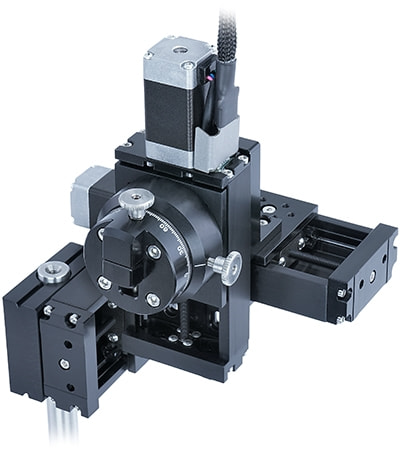
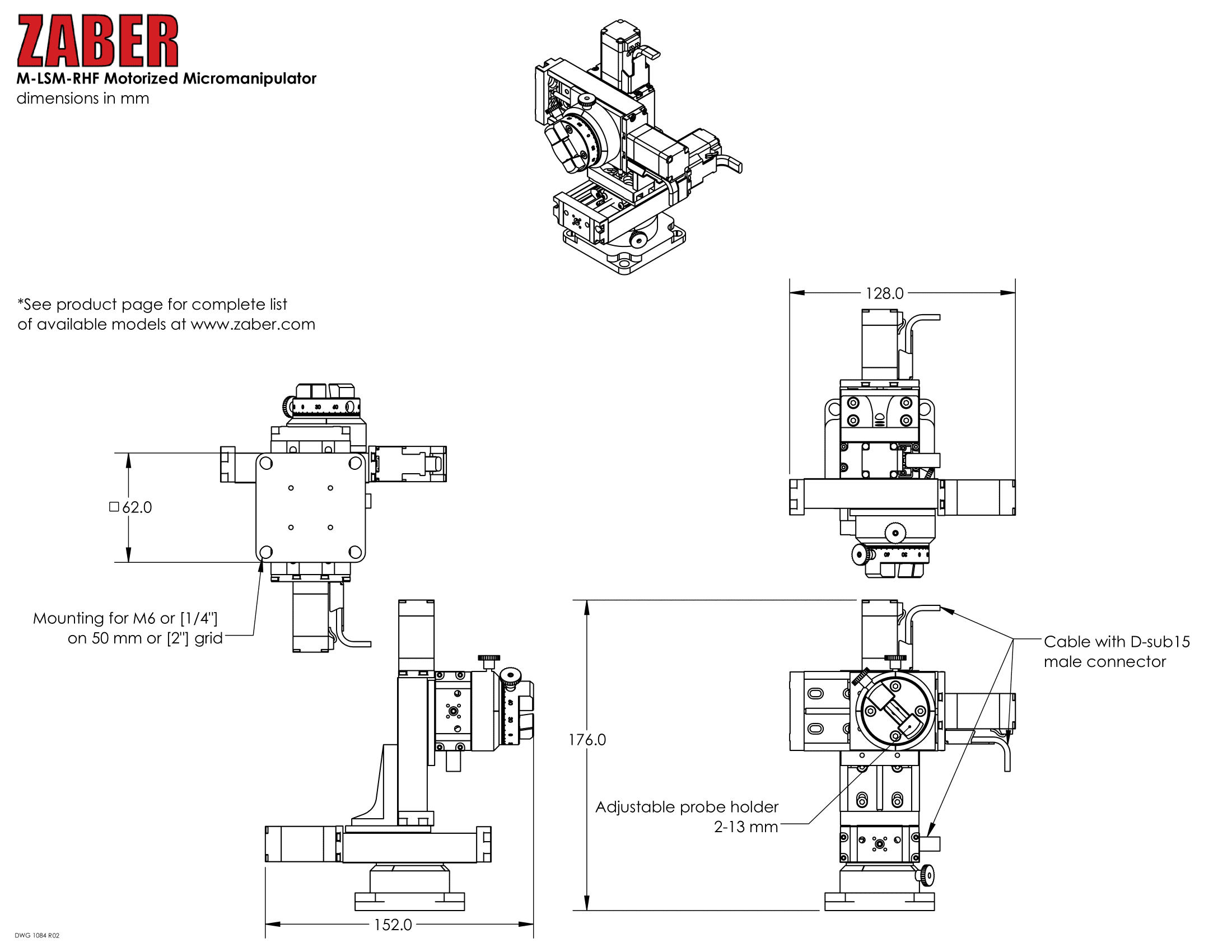
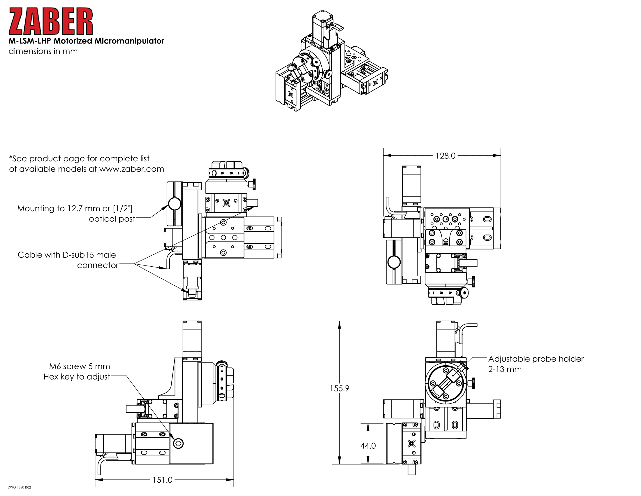
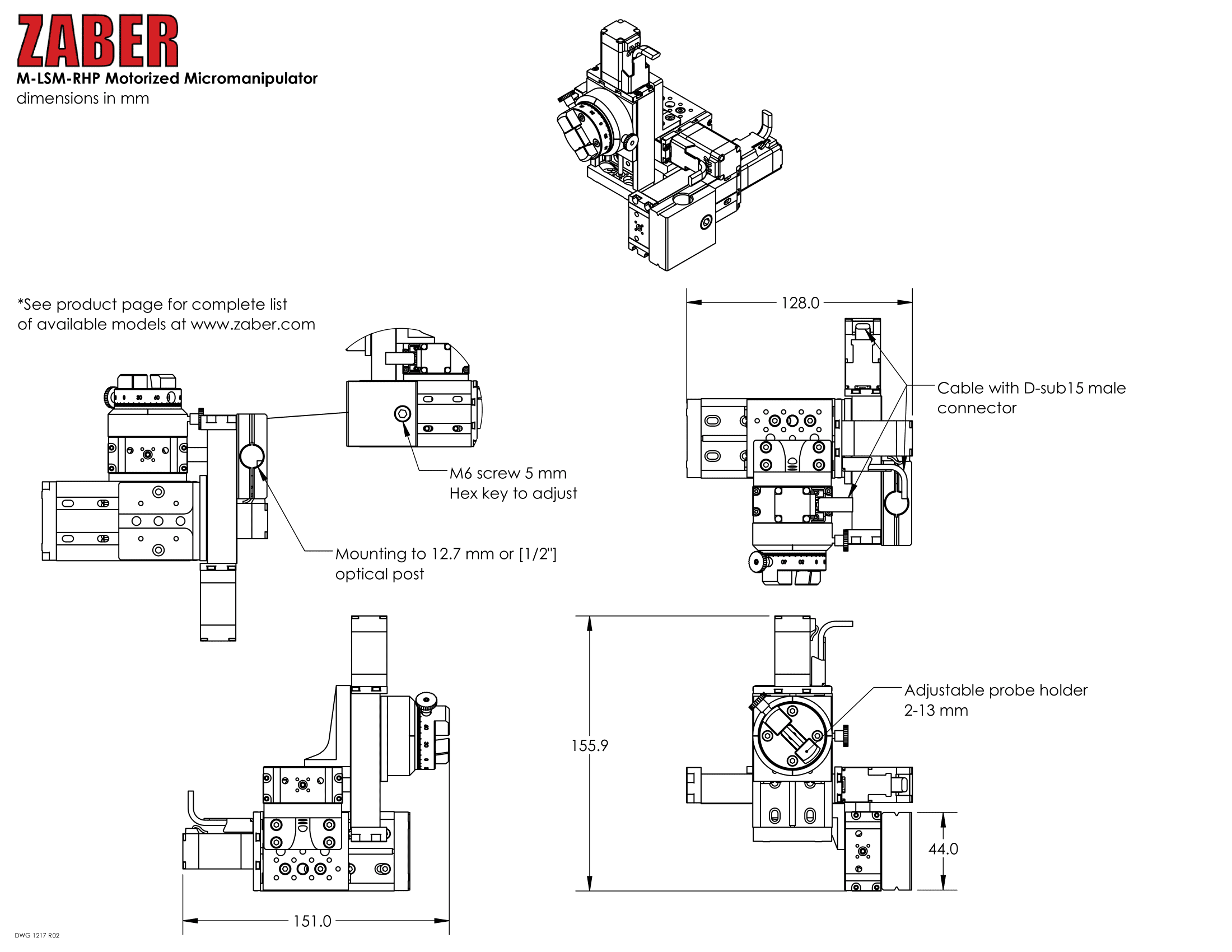
Zaber's M-LSM series of Micromanipulators are used to position probes under a microscope with a joystick or computer. They can be mounted to either metric or imperial optical breadboards. An adjustable probe holder allows mounting of probe diameters between 2 and 13 mm. The controller connects to the RS-232 or USB port of any computer.
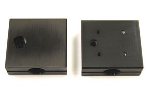
Mounting
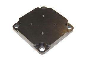
The M-LSM micromanipulator is specified either with a flat base or an adaptor plate to mount to an optical post.
Installing a M-LSM with a flat base
-
Right hand M-LSM that mounts to a flat base. Ships assembled as shown above.
-
Bracket to mount to flat base shown for clarity, but remains assembled during installation.
-
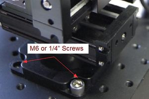
Using either four M6 screws on a 50mm grid or 1/2" screws on a 2" grid attach M-LSM micromanipulator to a flat base.
Installing a M-LSM to an Optical Post
-

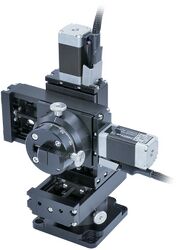
Left hand post mounted M-LSM. Ships assembled as shown above, excluding the optical post.
-
Bracket to mount to an optical post for either a 1/2" or 12.7mm optical post.
-

Slide bracket over optical post into desired position and tighten M6 screw with 5 mm allen key to lock M-LSM in position.
-

Ensure that the optical post doesn't extend too far, or it will interfere. The above image shows incorrect installation where the optical post will obstruct the movement.
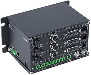
Powering up an M-LSM
-
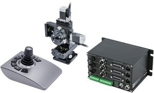
Main components of M-LSM
-
Each LSM stage has dangling cable connectors labelled AXIS 1, 2 & 3 to be connected to appropriate X-MCC3 driver axes.
-

The X-JOY3 is connected to the X-MCC3 through the X-DC06 cable
Once the system has been installed, verify that each axis is working correctly by moving the joystick. Please note that each stage needs to be homed before it is able to move the full length of travel. Homing the devices is done by using the joystick to move each axis to the end of travel on the side of the motor.
Should you wish to mount alternative probes to the M-LSM custom adaptor plates are available upon request. Please contact Zaber technical support at 1-888-276-8033 or contact@zaber.com for more information.
Operation
The joystick is pre-programmed with the following settings.
-
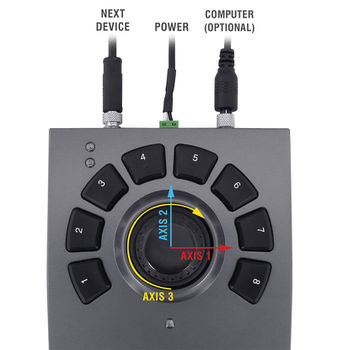
Axis numbers are labelled on the corresponding stage cables.
| Joystick Settings | ||||
|---|---|---|---|---|
| Key | Event 1 | Event 2 | Event 3 | Event 4 |
| 1 | Stop | Set active axis 3 (Z) | Set axis velocity scale 0 (Deactivate Z) | |
| 2 | Set Reference Position | Go to Reference Position | ||
| 3 | Set Reference Position | Go to Reference Position | ||
| 4 | Set Reference Position | Go to Reference Position | ||
| 5 | Set Reference Position | Go to Reference Position | ||
| 6 | Set active axis 1 (X) | Set axis velocity scale 3000 | Set axis velocity scale 80000 | |
| 7 | Set active axis 2 (Y) | Set axis velocity scale 3000 | Set axis velocity scale 80000 | |
| 8 | Set active axis 3 (Z) | Set axis velocity scale 3000 | Set axis velocity scale 80000 | |
Button 8 re-activates the Z-axis.
-
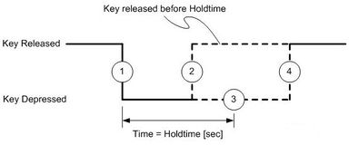
Diagram of the event path for each key. The events are numbered from 1-4. This diagram shows what events are issued depending on how long you hold the key.
| Accessing key events | |||
|---|---|---|---|
| Event 1 | Event 2 | Event 3 | Event 4 |
| Press button | Quick release of button, less than 2 seconds | Hold button longer than 2 seconds | Release button after holding longer than 2 seconds |
The orange led will flash after about 2 seconds to signify that event 3 has been triggered.
If you would like to change the settings of the joystick refer to the X-JOY3 user manual.
Most of the information you will need to operate the stage using the X-MCC controller can be found in the X-MCC User Manual.
Trajectory Control and Behaviour
This section describes the behaviour of the axis trajectory when a movement command is issued.
Software Position Limits
The travel range of the axis is limited by the Minimum Position and Maximum Position settings. The factory settings for the axis are configured to match the physical travel range. If a customized range is desired, it can be changed by configuring the limit.min (T:106) and limit.max (T:44) settings to appropriate values. For the Current Position, query pos (T:60).
- Minimum Position
- When the Current Position is less than the Minimum Position value, the axis cannot move in the negative direction(towards the motor).
- Maximum Position
- When the Current Position is greater than the Maximum Position value, the axis cannot move in the positive direction(away from the motor).
Movement Speed
The movement speed of the axis depends on axis status and various speed settings. If the axis has not been initialized by the home (T:1) command or by moving towards the home end of the axis, movement speed will be constrained to fail-safe values. The home status of the axis can be determined by reading the limit.home.triggered(T:53:103) setting.
Movement speed of the axis is specified below:
- move vel (T:22)
- The axis will move at the specified speed regardless of home status.
- Knob movement in Velocity Mode
- The axis will move at the specified speed regardless of home status.
- The speed is specified by the knob.speedprofile (T:112) and knob.maxspeed (T:111) settings.
- Other movement commands - when the axis has not been homed
- The axis will move at the slower of the maxspeed (T:42) and limit.approach.maxspeed (T:41) settings.
- Other movement commands - when the axis has been homed
- The axis will move at the speed specified by the maxspeed (T:42) setting.
Warranty and Repair
For Zaber's policies on warranty and repair, please refer to the Ordering Policies.
Standard products
Standard products are any part numbers that do not contain the suffix ENG followed by a 4 digit number. Most, but not all, standard products are listed for sale on our website. All standard Zaber products are backed by a one-month satisfaction guarantee. If you are not satisfied with your purchase, we will refund your payment minus any shipping charges. Goods must be in brand new saleable condition with no marks. Zaber products are guaranteed for one year. During this period Zaber will repair any products with faults due to manufacturing defects, free of charge.
Custom products
Custom products are any part numbers containing the suffix ENG followed by a 4 digit number. Each of these products has been designed for a custom application for a particular customer. Custom products are guaranteed for one year, unless explicitly stated otherwise. During this period Zaber will repair any products with faults due to manufacturing defects, free of charge.
How to return products
Customers with devices in need of return or repair should contact Zaber to obtain an RMA form which must be filled out and sent back to us to receive an RMA number. The RMA form contains instructions for packing and returning the device. The specified RMA number must be included on the shipment to ensure timely processing.
Email Updates
If you would like to receive our periodic email newsletter including product updates and promotions.
Contact Information
Contact Zaber Technologies Inc by any of the following methods:
| Phone | 1-604-569-3780 (direct) 1-888-276-8033 (toll free in North America) |
|---|---|
| Fax | 1-604-648-8033 |
| #2 - 605 West Kent Ave. N., Vancouver, British Columbia, Canada, V6P 6T7 | |
| Web | www.zaber.com |
| Please visit our website for up to date email contact information. |
The original instructions for this product are available at https://www.zaber.com/manuals/M-LSM.
Appendix A: Default Settings
Please see the Zaber Support Page for default settings for this device.
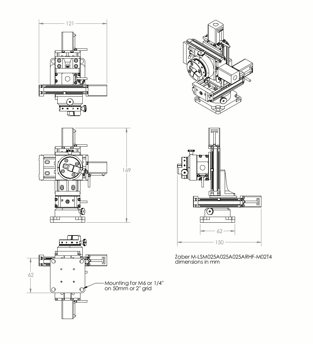
Product Drawings

Specifications
| Specification | Value | Alternate Unit |
|---|---|---|
| Microstep Size (Default Resolution) | 0.047625 µm | |
| Recommended Controller | MCC (48 V) Recommended | |
| AutoDetect | Yes | |
| Travel Range | 25.4 mm | 1.000" |
| Accuracy (unidirectional) | 15 µm | 0.000591" |
| Repeatability | < 3 µm | < 0.000118" |
| Backlash | < 12 µm | < 0.000472" |
| Maximum Speed | 26 mm/s | 1.024"/s |
| Minimum Speed | 0.000029 mm/s | 0.000001"/s |
| Speed Resolution | 0.000029 mm/s | 0.000001"/s |
| Encoder Type | None | |
| Peak Thrust | 55 N | 12.3 lb |
| Communication Interface | RS-232, USB 2.0 | |
| Communication Protocol | Zaber ASCII (Default), Zaber Binary | |
| Flatness of Travel | < 8 µm | < 0.000315" |
| Straightness of Travel | < 12 µm | < 0.000472" |
| Pitch | 0.02° | 0.349 mrad |
| Roll | 0.02° | 0.349 mrad |
| Yaw | 0.03° | 0.523 mrad |
| Probe Diameter Range | 2-13 mm | |
| Probe Angle Range | 360° | 6.283 rad |
| Linear Motion Per Motor Rev | 0.6096 mm | 0.024" |
| Motor Steps Per Rev | 200 | |
| Motor Type | Stepper (2 phase) | |
| Motor Rated Current | 600 mA/phase | |
| Motor Winding Resistance | 6.5 ohms/phase | |
| Motor Winding Inductance | 3.5 mH/phase | |
| Motor Rated Power | 6.9 watts | |
| Motor Connection | D-sub 15 | |
| Default Resolution | 1/64 of a step | |
| Guide Type | Recirculating ball bearing | |
| Mechanical Drive System | Precision lead screw | |
| Limit or Home Sensing | Magnetic hall sensor | |
| Axes of Motion | 3 | |
| Stage Parallelism | < 25 µm | < 0.000984" |
| Joystick Control | Velocity Mode | |
| Operating Temperature Range | 0-50 °C | |
| CE Compliant | Yes | |
| Vacuum Compatible | No | |
| Weight | 1.032 kg | 2.275 lb |
Charts and Notes
This product uses the FreeRTOS kernel. FreeRTOS is © 2026 Amazon.com, Inc. or its affiliates and is governed by the following license:
All rights reserved.
Permission is hereby granted, free of charge, to any person obtaining a copy of this software and associated documentation files (the "Software"), to deal in the Software without restriction, including without limitation the rights to use, copy, modify, merge, publish, distribute, sublicense, and/or sell copies of the Software, and to permit persons to whom the Software is furnished to do so, subject to the following conditions:
The above copyright notice and this permission notice shall be included in all copies or substantial portions of the Software.
THE SOFTWARE IS PROVIDED "AS IS", WITHOUT WARRANTY OF ANY KIND, EXPRESS OR IMPLIED, INCLUDING BUT NOT LIMITED TO THE WARRANTIES OF MERCHANTABILITY, FITNESS FOR A PARTICULAR PURPOSE AND NONINFRINGEMENT.
IN NO EVENT SHALL THE AUTHORS OR COPYRIGHT HOLDERS BE LIABLE FOR ANY CLAIM, DAMAGES OR OTHER LIABILITY, WHETHER IN AN ACTION OF CONTRACT, TORT OR OTHERWISE, ARISING FROM, OUT OF OR IN CONNECTION WITH THE SOFTWARE OR THE USE OR OTHER DEALINGS IN THE SOFTWARE.
This product uses the LZ4 compression library. LZ4 is © 2011–2016 Yann Collet and is governed by the following license:
All rights reserved.
Redistribution and use in source and binary forms, with or without modification, are permitted provided that the following conditions are met:
- Redistributions of source code must retain the above copyright notice, this list of conditions and the following disclaimer.
- Redistributions in binary form must reproduce the above copyright notice, this list of conditions and the following disclaimer in the documentation and/or other materials provided with the distribution.
THIS SOFTWARE IS PROVIDED BY THE COPYRIGHT HOLDERS AND CONTRIBUTORS "AS IS" AND ANY EXPRESS OR IMPLIED WARRANTIES, INCLUDING, BUT NOT LIMITED TO, THE IMPLIED WARRANTIES OF MERCHANTABILITY AND FITNESS FOR A PARTICULAR PURPOSE ARE DISCLAIMED. IN NO EVENT SHALL THE COPYRIGHT HOLDER OR CONTRIBUTORS BE LIABLE FOR ANY DIRECT, INDIRECT, INCIDENTAL, SPECIAL, EXEMPLARY, OR CONSEQUENTIAL DAMAGES (INCLUDING, BUT NOT LIMITED TO, PROCUREMENT OF SUBSTITUTE GOODS OR SERVICES; LOSS OF USE, DATA, OR PROFITS; OR BUSINESS INTERRUPTION) HOWEVER CAUSED AND ON ANY THEORY OF LIABILITY, WHETHER IN CONTRACT, STRICT LIABILITY, OR TORT (INCLUDING NEGLIGENCE OR OTHERWISE) ARISING IN ANY WAY OUT OF THE USE OF THIS SOFTWARE, EVEN IF ADVISED OF THE POSSIBILITY OF SUCH DAMAGE.