LRU-E Series User's Manual
High Load, High Stiffness, Screw Drive Linear Stage with Optional Brakes
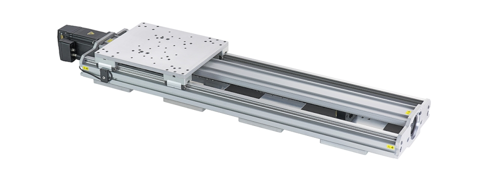
Table of Contents
Table of Contents
Disclaimer
Zaber’s products are not intended for use in any critical medical, aviation, or military applications or situations where a product's use or failure could cause personal injury, death, or damage to property. Zaber disclaims any warranty of fitness for a particular purpose. The user of this product agrees to Zaber's general terms and conditions of sale.
Precautions
Zaber's autodetect peripheral axes are designed to be used effortlessly with Zaber's line of autodetect controllers. The LRU-E includes onboard memory that allows Zaber's controllers to autodetect the model and set reasonable parameters. See the Protocol Manual for more information on how to modify the settings. Damage to the axis may result if the settings are not correct. To use your Zaber peripheral with a third-party controller, review the motor, sensor, and encoder specifications and pin-outs carefully.
 Cross-wiring Risk: This product has two connections to the Zaber controller: an M12 connector for the motor phase wires and a D-Sub connector (DB15 or DB26) for sensor signals. When connecting two or more peripherals which have the M12 connector, care must be taken to ensure that the two cables are connected to the same axis on the controller. Zaber recommends using color-coding to provide a visual check of wiring correctness.
Pinch Hazard: Keep hands away from the moving carriage. Use caution when mounting components near the path of the carriage; they may create unexpected pinch hazards.
Backdriving: If motor power is suddenly lost, vertical loads may quickly fall and high inertial loads may fail to stop. This can cause personal injury in addition to damaging the load, the device, and electronics. It is strongly recommended that if unpredictable falling loads could result in system or bodily harm to not exceed the devices published backdriving force.
 Caution: The motor in this device can exceed 60° C during normal operation and become hot enough to cause burns. Take precautions to prevent contact with the motor.
Dynamic Stops: The power-off brake is intended to prevent damage and maintain the position of a static load in the event of a power loss. Precautions should be taken to avoid dynamic braking when possible, as this may significantly reduce brake lifetime and result in failure of the brake.
Noise: Under high load and high speed applications, this device may emit up to 80 dB, 1 meter away from the motor. Use appropriate hearing protection for your exposure time.
 Important: Mounting large objects to the carriage or using this component in a multi-axis system may create new or unexpected risks. Always perform a risk analysis for your complete system in its operating environment.
Relubrication Procedure
Many factors affect the lifetime of the grease and bearings including duty cycle, environment, travel length, stage orientation, and loading configuration. As a general guideline for usage in a clean office environment, the recommended re-lubrication interval is 250 km with an inspection after every 1500 hours of continuous operation. Inspection should be done by wiping a bearing rail with a clean, lint-free wipe and ensuring that there is clean, wetted grease present.
Harsh environment, short travel, vertically oriented, and high duty cycle applications require more frequent re-lubrication and inspection. Contact an Applications Engineer to discuss your application for more specific recommendations.
Short travel can cause an insufficient distribution of lubricant amongst the rolling elements of the bearing system. For recirculating bearing guide types, short travel is equal to or less than the length of the carriage. For crossed-roller bearing guide types, short travel is equal to or less than twice the spacing of the rolling elements (typically 5-6 mm). If your application is considered short travel, it is recommended to occasionally drive the stage throughout its full travel range to maintain an even lubrication film over the entire guide surface. More frequent re-lubrication and inspection may be required in these applications.
Contact Zaber support for relubrication kit SG133. We recommend using Shell Gadus S2 V220 2 or similar lithium thickened petroleum grease.
-

Insert angled syringe tip into grease hole in bearing end cap. Move the carriage about 50 mm while squeezing approximately 0.2 mL of grease from the syringe. Repeat for all four end caps. Cycle the carriage through the full range of travel.
Ball Screw Relubrication
Like the linear bearings, many factors affect the lifetime of the grease and ball screw. We recommend an inspection of the ball screw surface every 200 hours of continuous operation and a relubrication at least every 500 hours with Shell Gadus S2 V220 2, available in the relubrication kit SG133.
Conventions used throughout this document
- Fixed width type indicates communication to and from a device. The ↵ symbol indicates a carriage return, which can be achieved by pressing enter when using a terminal program.
- An ASCII command followed by (T:xx) indicates a legacy T-Series Binary Protocol command that achieves the same result. For example,
- move abs 10000 (T:20:10000) shows that a move abs ASCII command can also be achieved with Binary command number 20.
- Not all ASCII commands have an equivalent Binary counterpart.
Device Overview
AutoDetect
Your LRU-E peripheral is equipped with AutoDetect, a feature that allows a Zaber controller to automatically configure its settings for the peripheral when it is connected.
Important: The controller should always be powered down before disconnecting or connecting your LRU-E peripheral.
To connect the peripheral to a controller:
- Power off the controller.
- Connect the LRU-E peripheral.
- Power on the controller.
- The controller will activate the peripheral shortly after it is powered on.
Controller Compatibility: X-MCC (revision 2+) with firmware (FW 7.34+) is required for the operation of devices with a power-off brake. See the Zaber controller user manual for more details on peripheral activation and control.
Connectors
Recommended controller(s) for your LRU-E peripheral are provided in the product specifications. Zaber's controllers and peripherals are designed for ease of use when used together. Optimal settings for each peripheral are automatically detected by Zaber's controllers when the device is connected.
For reference, the pinout for the peripheral cable connectors is shown below:
6 Amp Motor Interface
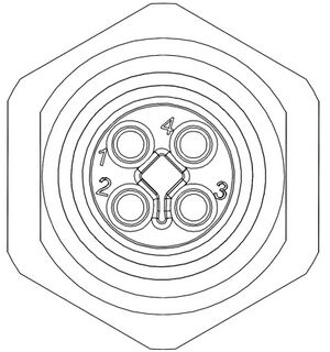
Male T-Coded M12 Connector |
Pin # | Stepper Motor Connection |
|---|---|---|
| 1 | Motor A2 | |
| 2 | Motor A1 | |
| 3 | Motor B2 | |
| 4 | Motor B1 |
NOTE: If using this connector the four motor pins on the D-sub connector must not be used.
Pinout for D-sub 15 Connectors (peripherals)
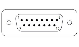
Male DB15 Connector |
Pin # | Function |
|---|---|---|
| 1 | +5V for Limits & Encoder | |
| 2 | AutoDetect Data | |
| 3 | N.C. | |
| 4 | Away Sensor | |
| 5 | Home Sensor | |
| 6 | Ground | |
| 7 | N/C | |
| 8 | N/C | |
| 9 | AutoDetect Clock | |
| 10 | Encoder A | |
| 11 | Encoder B | |
| 12 | Encoder Index | |
| 13 | Ground | |
| 14 | N/C | |
| 15 | N/C |
Pinout for D-sub 26 Connectors (peripherals) for Brake-Equipped Products
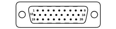
Male High Density D-sub26 Connector |
Pin | Description | Pin | Description |
|---|---|---|---|---|
| 1 | AutoDetect Clock | 14 | Single-ended Encoder Index | |
| 2 | AutoDetect Data | 15 | +5V | |
| 3 | N.C. | 16 | Ground | |
| 4 | N.C. | 17 | Brake- | |
| 5 | Home Limit Sensor | 18 | N.C. | |
| 6 | N.C. | 19 | N.C. | |
| 7 | Ground | 20 | N.C. | |
| 8 | N.C. | 21 | N.C. | |
| 9 | N.C. | 22 | Single-ended Encoder A | |
| 10 | N.C. | 23 | Single-ended Encoder B | |
| 11 | N.C. | 24 | N.C. | |
| 12 | N.C. | 25 | Brake+ | |
| 13 | N.C. | 26 | N.C. |
NOTE: All hall sensor signals (for limits or motor phase) are open collector and require a pull-up on the controller.
NOTE: All single-ended encoder inputs are non-isolated 5V TTL lines.
External Hall Sensor
-
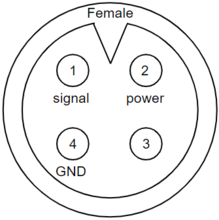
Device Connector
-
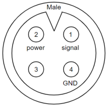
Sensor Connector
| Pin | Description |
|---|---|
| 1 | Signal |
| 2 | +5V |
| 3 | Reserved |
| 4 | Ground |
NOTE: The signal is pulled up to the internal supply rail and is designed to be pulled low by an open collector.
NOTE: Sensor inputs are non-isolated 5V TTL lines.
Alternate Controllers
The LRU-E can be controlled by any 2-phase stepper motor controller with limit sensor and appropriate encoder and brake input. We do not recommend using your own controller unless you are familiar with how to control a stepper motor with hall sensor limit switches, encoders, and power-off brakes. Improper use can result in excessive heat generated by the device, potentially causing harm to operators or damage to the system. Damage to the device due to incorrect wiring is not covered by warranty.
Power Supply Requirements
The LRU-E motor can draw high currents. When used with Zaber’s MCC controllers, each LRU-E motor must have a dedicated high-current power supply. Zaber strongly recommends using Zaber’s PS15S-48V65 power supply, or a dedicated power supply with sufficient current capacity to power the LRU-E.
Motors & Encoders
For motor and encoder information see the LRU-E product page
Limit Sensors
Hall effect sensors are used in the LRU-E as home sensors. The Hall sensors used are part number A1120LLHLT-T made by Allegro. Click here for data sheet. Your controller should be configured so the axis stops almost immediately (quick deceleration) when the sensors are triggered.
- PCB wire colour code:
- 5 Vdc input - red
- Home signal - yellow
- Away signal - white
- Ground - black
The Hall sensor has an open-collector output. The default output is high impedance when the Hall sensor is not active. When the sensor detects a magnet, the Hall sensor pulls the output low to ground.
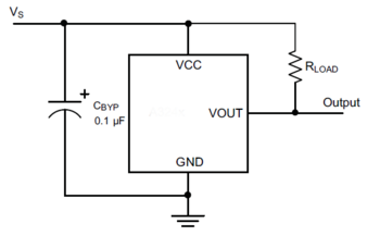
If you are not using a Zaber controller, ensure that your controller has a pull-up resistor on the output line of each Hall sensor as shown in the diagram. The bypass capacitor is optional, but may help to eliminate false triggering in noisy environments. The typical value for the pull-up resistor (RLOAD) is 10 kΩ and for the bypass capacitor is 0.1 uF to 1 uF. The larger the capacitance, the better the noise filtering but the slower the response time.
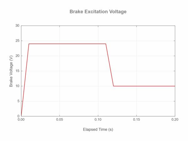
Power-off Brake
It is necessary to follow the recommended values for excitation and hold voltages:
- The initial excitation voltage of 24 V should be applied for at least 100 ms to ensure the power-off brake is opened.
- A hold voltage of 10 V can then be applied to reduce excess heating of the brake.
- When open, the brake will consume ~2 watts to remain open.
Brake Settings: The brake must be correctly configured in order to operate correctly. In Zaber’s controllers, there are multiple settings that affect correct operation. The default settings for the LRU-E product may need to be modified for some applications. When modifying these settings, be sure to follow the guidance in the Protocol Manual.
Installation
Tip: To obtain the best pitch, roll, yaw and straightness performance, mount the stage to a known flat, stiff surface. Our tests were performed on a granite table, grade A flatness.
Important: Mounting large objects to the carriage or using this component in a multi-axis system may create new or unexpected risks. Always perform a risk analysis for your complete system in its operating environment.
Tipping Hazard! Ensure stage is fastened to a secure surface before mounting load on carriage. An unmounted stage with a load presents a tipping hazard. Ensure loads are mounted securely to the carriage of the stage.
180 mm Wide Variants
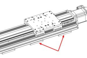
Mounting 180 mm wide variants requires the removal of the drive screw cover.
Pinch Hazard! Do not operate the device without the drive screw cover. It serves to protect users from high-consequence pinch hazards.
-
Position the carriage where it will not be in the way of mounting the device and remove power from the stage. You may need to manually turn the ball screw to fully access all the mounting locations.
-
Lock out the stage
-
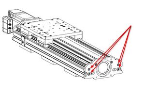
For any length stages: You may remove the end plate to remove the drive screw cover. Remove the four screws holding the end plate to the extrusions and slide the end plate and drive screw cover out of the end of the stage.
-
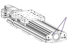
For stages with more than 500 mm travel: You do not have to remove the end plate to remove the drive screw cover. Remove the two screws holding the drive screw cover from the end plate and lift the drive screw cover out of the stage.
T-Slot Compatibility
The LRU is built on the LC40 linear guide platform. It is designed to be compatible with most common 40 mm T-slot extrusion framing systems. The two main requirements for compatibility are a 40 mm square profile width and an 8 mm slot width. While we have not exhaustively tested all systems and components, the following framing systems meet this basic compatibility requirements:
- 80/20 40 Series
- McMaster Carr 40 mm
- Parker-Hannifin 40 Series
- item Profile 8
- Parco 40 Series
- TSLOTS T40
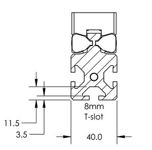
LC40 T-Slot Compatibility
Trajectory Control and Behaviour
This section describes the behaviour of the axis trajectory when a movement command is issued.
Software Position Limits
The travel range of the axis is limited by the Minimum Position and Maximum Position settings. The factory settings for the axis are configured to match the physical travel range. If a customized range is desired, it can be changed by configuring the limit.min (T:106) and limit.max (T:44) settings to appropriate values. For the Current Position, query pos (T:60).
- Minimum Position
- When the Current Position is less than the Minimum Position value, the axis cannot move in the negative direction(towards the motor).
- Maximum Position
- When the Current Position is greater than the Maximum Position value, the axis cannot move in the positive direction(away from the motor).
Movement Speed
The movement speed of the axis depends on axis status and various speed settings. If the axis has not been initialized by the home (T:1) command or by moving towards the home end of the axis, movement speed will be constrained to fail-safe values. The home status of the axis can be determined by reading the limit.home.triggered(T:53:103) setting.
Movement speed of the axis is specified below:
- move vel (T:22)
- The axis will move at the specified speed regardless of home status.
- Knob movement in Velocity Mode
- The axis will move at the specified speed regardless of home status.
- The speed is specified by the knob.speedprofile (T:112) and knob.maxspeed (T:111) settings.
- Other movement commands - when the axis has not been homed
- The axis will move at the slower of the maxspeed (T:42) and limit.approach.maxspeed (T:41) settings.
- Other movement commands - when the axis has been homed
- The axis will move at the speed specified by the maxspeed (T:42) setting.
Power-Off Brake Control
Brake Settings: The brake must be correctly configured in order to operate correctly. In Zaber’s controllers, there are multiple settings that affect correct operation. The default settings for the LRU-E product may need to be modified for some applications. When modifying these settings, be sure to follow the guidance in the Protocol Manual.
Described below are the recommended procedures for operating a brake-equipped device:
- Dynamic Brake Engagement - For Position Holding After Faults
- The power-off brake opens by default when the system is powered up. The brake will close if the device stalls, is displaced while stationary, the driver is disabled, or the power is interrupted. Repeated dynamic stopping may reduce the lifetime of the brake. We strongly recommend avoiding dynamic braking when possible.
- Stationary Brake Engagement - For Position Holding
- The power-off brake opens by default when the system is powered up. To change the brake state, use brake.mode.
- The order of operations to set a retaining position should follow:
- Open the brake by setting brake.mode to 1.
- Allow 100 ms for the brake to open.
- Move the positioner.
- Close the brake by setting brake.mode to 0.
- Allow 100 ms for the brake to close.
- If accuracy is required, the driver.current.hold↵ (T:39) should remain on to prevent slight shifts in the device position.
- Stationary Brake Engagement - For Reducing Motor Heat
- The power-off brake opens by default when the system is powered up. To change the brake state, use brake.mode. To reduce heat generated in the motor, use the driver disable command in between moves.
- The order of operations to maintain a vertical position, and disabling the driver to reduce heat, should follow:
- Set the hold current to the appropriate value based on load (see defaults on website).
- Move the positioner to the intended location.
- Send the driver disable command. The brake will automatically close.
- When ready to move again, send the driver enable command. The brake will open.
- Move the positioner as normal
- Turning off the hold current will cause a small displacement of the positioner.
- Manual Device Movement
- Manual Device movement requires disabling the encoder displacement detection to prevent engagement of the power-off brake. The order of operations for manual movement should follow:
- Remove any load from the positioner.
- Disable closed-loop control by setting cloop.enable to 0 .
- Set the hold current to 0.
- Move the positioner manually by hand. For screw driven linear devices, turning the lead screw can assist in achieving smaller increments during manual movement.
Warranty and Repair
For Zaber's policies on warranty and repair, please refer to the Ordering Policies.
Standard products
Standard products are any part numbers that do not contain the suffix ENG followed by a 4 digit number. Most, but not all, standard products are listed for sale on our website. All standard Zaber products are backed by a one-month satisfaction guarantee. If you are not satisfied with your purchase, we will refund your payment minus any shipping charges. Goods must be in brand new saleable condition with no marks. Zaber products are guaranteed for one year. During this period Zaber will repair any products with faults due to manufacturing defects, free of charge.
Custom products
Custom products are any part numbers containing the suffix ENG followed by a 4 digit number. Each of these products has been designed for a custom application for a particular customer. Custom products are guaranteed for one year, unless explicitly stated otherwise. During this period Zaber will repair any products with faults due to manufacturing defects, free of charge.
How to return products
Customers with devices in need of return or repair should contact Zaber to obtain an RMA form which must be filled out and sent back to us to receive an RMA number. The RMA form contains instructions for packing and returning the device. The specified RMA number must be included on the shipment to ensure timely processing.
Email Updates
If you would like to receive our periodic email newsletter including product updates and promotions.
Contact Information
Contact Zaber Technologies Inc by any of the following methods:
| Phone | 1-604-569-3780 (direct) 1-888-276-8033 (toll free in North America) |
|---|---|
| Fax | 1-604-648-8033 |
| #2 - 605 West Kent Ave. N., Vancouver, British Columbia, Canada, V6P 6T7 | |
| Web | www.zaber.com |
| Please visit our website for up to date email contact information. |
The original instructions for this product are available at https://www.zaber.com/manuals/LRU-E.
Appendix A: Default Settings
Please see the Zaber Support Page for default settings for this device.
Product Drawings
Specifications
Comparison
| Part Number | Travel Range | Accuracy (unidirectional) | Maximum Speed | Maximum Axial Brake Force |
|---|---|---|---|---|
| LRU0250H18-BE01T12A | 250 mm (9.843") | 90 µm (0.003543") | 350 mm/s (13.78"/s) | 2850 N (640.7 lb) |
| LRU0250H18-E01T11A | 250 mm (9.843") | 90 µm (0.003543") | 350 mm/s (13.78"/s) | |
| LRU0250H25-BE01T12A | 250 mm (9.843") | 90 µm (0.003543") | 350 mm/s (13.78"/s) | 2850 N (640.7 lb) |
| LRU0250H25-E01T11A | 250 mm (9.843") | 90 µm (0.003543") | 350 mm/s (13.78"/s) | |
| LRU0500H18-BE01T12A | 500 mm (19.685") | 160 µm (0.006299") | 330 mm/s (12.992"/s) | 2850 N (640.7 lb) |
| LRU0500H18-E01T11A | 500 mm (19.685") | 160 µm (0.006299") | 330 mm/s (12.992"/s) | |
| LRU0500H25-BE01T12A | 500 mm (19.685") | 160 µm (0.006299") | 330 mm/s (12.992"/s) | 2850 N (640.7 lb) |
| LRU0500H25-E01T11A | 500 mm (19.685") | 160 µm (0.006299") | 330 mm/s (12.992"/s) | |
| LRU1000H18-BE01T12A | 1000 mm (39.37") | 250 µm (0.009842") | 300 mm/s (11.811"/s) | 2850 N (640.7 lb) |
| LRU1000H18-E01T11A | 1000 mm (39.37") | 250 µm (0.009842") | 300 mm/s (11.811"/s) | |
| LRU1000H25-BE01T12A | 1000 mm (39.37") | 250 µm (0.009842") | 300 mm/s (11.811"/s) | 2850 N (640.7 lb) |
| LRU1000H25-E01T11A | 1000 mm (39.37") | 250 µm (0.009842") | 300 mm/s (11.811"/s) | |
| LRU1500H18-BE01T12A | 1500 mm (59.055") | 350 µm (0.013779") | 200 mm/s (7.874"/s) | 2850 N (640.7 lb) |
| LRU1500H18-E01T11A | 1500 mm (59.055") | 350 µm (0.013779") | 200 mm/s (7.874"/s) | |
| LRU1500H25-BE01T12A | 1500 mm (59.055") | 350 µm (0.013779") | 200 mm/s (7.874"/s) | 2850 N (640.7 lb) |
| LRU1500H25-E01T11A | 1500 mm (59.055") | 350 µm (0.013779") | 200 mm/s (7.874"/s) | |
| LRU2000H18-BE01T12A | 2000 mm (78.74") | 425 µm (0.016732") | 120 mm/s (4.724"/s) | 2850 N (640.7 lb) |
| LRU2000H18-E01T11A | 2000 mm (78.74") | 425 µm (0.016732") | 120 mm/s (4.724"/s) | |
| LRU2000H25-BE01T12A | 2000 mm (78.74") | 425 µm (0.016732") | 120 mm/s (4.724"/s) | 2850 N (640.7 lb) |
| LRU2000H25-E01T11A | 2000 mm (78.74") | 425 µm (0.016732") | 120 mm/s (4.724"/s) |
| Part Number | Maximum Moment (Pitch) | Maximum Moment (Roll) | Maximum Moment (Yaw) | Flatness of Travel |
|---|---|---|---|---|
| LRU0250H18-BE01T12A | 240 N⋅m (177.1 lb⋅ft) | 240 N⋅m (177.12 lb⋅ft) | 240 N⋅m (177.12 lb⋅ft) | < 35 µm (< 0.001378") |
| LRU0250H18-E01T11A | 240 N⋅m (177.1 lb⋅ft) | 240 N⋅m (177.12 lb⋅ft) | 240 N⋅m (177.12 lb⋅ft) | < 35 µm (< 0.001378") |
| LRU0250H25-BE01T12A | 360 N⋅m (265.7 lb⋅ft) | 360 N⋅m (265.68 lb⋅ft) | 360 N⋅m (265.68 lb⋅ft) | < 35 µm (< 0.001378") |
| LRU0250H25-E01T11A | 360 N⋅m (265.7 lb⋅ft) | 360 N⋅m (265.68 lb⋅ft) | 360 N⋅m (265.68 lb⋅ft) | < 35 µm (< 0.001378") |
| LRU0500H18-BE01T12A | 240 N⋅m (177.1 lb⋅ft) | 240 N⋅m (177.12 lb⋅ft) | 240 N⋅m (177.12 lb⋅ft) | < 70 µm (< 0.002756") |
| LRU0500H18-E01T11A | 240 N⋅m (177.1 lb⋅ft) | 240 N⋅m (177.12 lb⋅ft) | 240 N⋅m (177.12 lb⋅ft) | < 70 µm (< 0.002756") |
| LRU0500H25-BE01T12A | 360 N⋅m (265.7 lb⋅ft) | 360 N⋅m (265.68 lb⋅ft) | 360 N⋅m (265.68 lb⋅ft) | < 70 µm (< 0.002756") |
| LRU0500H25-E01T11A | 360 N⋅m (265.7 lb⋅ft) | 360 N⋅m (265.68 lb⋅ft) | 360 N⋅m (265.68 lb⋅ft) | < 70 µm (< 0.002756") |
| LRU1000H18-BE01T12A | 240 N⋅m (177.1 lb⋅ft) | 240 N⋅m (177.12 lb⋅ft) | 240 N⋅m (177.12 lb⋅ft) | < 140 µm (< 0.005512") |
| LRU1000H18-E01T11A | 240 N⋅m (177.1 lb⋅ft) | 240 N⋅m (177.12 lb⋅ft) | 240 N⋅m (177.12 lb⋅ft) | < 140 µm (< 0.005512") |
| LRU1000H25-BE01T12A | 360 N⋅m (265.7 lb⋅ft) | 360 N⋅m (265.68 lb⋅ft) | 360 N⋅m (265.68 lb⋅ft) | < 140 µm (< 0.005512") |
| LRU1000H25-E01T11A | 360 N⋅m (265.7 lb⋅ft) | 360 N⋅m (265.68 lb⋅ft) | 360 N⋅m (265.68 lb⋅ft) | < 140 µm (< 0.005512") |
| LRU1500H18-BE01T12A | 240 N⋅m (177.1 lb⋅ft) | 240 N⋅m (177.12 lb⋅ft) | 240 N⋅m (177.12 lb⋅ft) | < 180 µm (< 0.007087") |
| LRU1500H18-E01T11A | 240 N⋅m (177.1 lb⋅ft) | 240 N⋅m (177.12 lb⋅ft) | 240 N⋅m (177.12 lb⋅ft) | < 180 µm (< 0.007087") |
| LRU1500H25-BE01T12A | 360 N⋅m (265.7 lb⋅ft) | 360 N⋅m (265.68 lb⋅ft) | 360 N⋅m (265.68 lb⋅ft) | < 180 µm (< 0.007087") |
| LRU1500H25-E01T11A | 360 N⋅m (265.7 lb⋅ft) | 360 N⋅m (265.68 lb⋅ft) | 360 N⋅m (265.68 lb⋅ft) | < 180 µm (< 0.007087") |
| LRU2000H18-BE01T12A | 240 N⋅m (177.1 lb⋅ft) | 240 N⋅m (177.12 lb⋅ft) | 240 N⋅m (177.12 lb⋅ft) | < 220 µm (< 0.008661") |
| LRU2000H18-E01T11A | 240 N⋅m (177.1 lb⋅ft) | 240 N⋅m (177.12 lb⋅ft) | 240 N⋅m (177.12 lb⋅ft) | < 220 µm (< 0.008661") |
| LRU2000H25-BE01T12A | 360 N⋅m (265.7 lb⋅ft) | 360 N⋅m (265.68 lb⋅ft) | 360 N⋅m (265.68 lb⋅ft) | < 220 µm (< 0.008661") |
| LRU2000H25-E01T11A | 360 N⋅m (265.7 lb⋅ft) | 360 N⋅m (265.68 lb⋅ft) | 360 N⋅m (265.68 lb⋅ft) | < 220 µm (< 0.008661") |
| Part Number | Straightness of Travel | Pitch | Roll | Yaw |
|---|---|---|---|---|
| LRU0250H18-BE01T12A | < 35 µm (< 0.001378") | 0.03° (0.523 mrad) | 0.03° (0.523 mrad) | 0.03° (0.523 mrad) |
| LRU0250H18-E01T11A | < 35 µm (< 0.001378") | 0.03° (0.523 mrad) | 0.03° (0.523 mrad) | 0.03° (0.523 mrad) |
| LRU0250H25-BE01T12A | < 35 µm (< 0.001378") | 0.03° (0.523 mrad) | 0.03° (0.523 mrad) | 0.03° (0.523 mrad) |
| LRU0250H25-E01T11A | < 35 µm (< 0.001378") | 0.03° (0.523 mrad) | 0.03° (0.523 mrad) | 0.03° (0.523 mrad) |
| LRU0500H18-BE01T12A | < 70 µm (< 0.002756") | 0.06° (1.047 mrad) | 0.06° (1.047 mrad) | 0.06° (1.047 mrad) |
| LRU0500H18-E01T11A | < 70 µm (< 0.002756") | 0.06° (1.047 mrad) | 0.06° (1.047 mrad) | 0.06° (1.047 mrad) |
| LRU0500H25-BE01T12A | < 70 µm (< 0.002756") | 0.06° (1.047 mrad) | 0.06° (1.047 mrad) | 0.06° (1.047 mrad) |
| LRU0500H25-E01T11A | < 70 µm (< 0.002756") | 0.06° (1.047 mrad) | 0.06° (1.047 mrad) | 0.06° (1.047 mrad) |
| LRU1000H18-BE01T12A | < 140 µm (< 0.005512") | 0.09° (1.57 mrad) | 0.09° (1.57 mrad) | 0.09° (1.57 mrad) |
| LRU1000H18-E01T11A | < 140 µm (< 0.005512") | 0.09° (1.57 mrad) | 0.09° (1.57 mrad) | 0.09° (1.57 mrad) |
| LRU1000H25-BE01T12A | < 140 µm (< 0.005512") | 0.09° (1.57 mrad) | 0.09° (1.57 mrad) | 0.09° (1.57 mrad) |
| LRU1000H25-E01T11A | < 140 µm (< 0.005512") | 0.09° (1.57 mrad) | 0.09° (1.57 mrad) | 0.09° (1.57 mrad) |
| LRU1500H18-BE01T12A | < 210 µm (< 0.008268") | 0.11° (1.919 mrad) | 0.11° (1.919 mrad) | 0.11° (1.919 mrad) |
| LRU1500H18-E01T11A | < 210 µm (< 0.008268") | 0.11° (1.919 mrad) | 0.11° (1.919 mrad) | 0.11° (1.919 mrad) |
| LRU1500H25-BE01T12A | < 210 µm (< 0.008268") | 0.11° (1.919 mrad) | 0.11° (1.919 mrad) | 0.11° (1.919 mrad) |
| LRU1500H25-E01T11A | < 210 µm (< 0.008268") | 0.11° (1.919 mrad) | 0.11° (1.919 mrad) | 0.11° (1.919 mrad) |
| LRU2000H18-BE01T12A | < 280 µm (< 0.011024") | 0.12° (2.094 mrad) | 0.12° (2.094 mrad) | 0.12° (2.094 mrad) |
| LRU2000H18-E01T11A | < 280 µm (< 0.011024") | 0.12° (2.094 mrad) | 0.12° (2.094 mrad) | 0.12° (2.094 mrad) |
| LRU2000H25-BE01T12A | < 280 µm (< 0.011024") | 0.12° (2.094 mrad) | 0.12° (2.094 mrad) | 0.12° (2.094 mrad) |
| LRU2000H25-E01T11A | < 280 µm (< 0.011024") | 0.12° (2.094 mrad) | 0.12° (2.094 mrad) | 0.12° (2.094 mrad) |
| Part Number | Motor Connection | Weight | ||
|---|---|---|---|---|
| LRU0250H18-BE01T12A | M12 T-code (motor) and D-sub 26 (sensors) | 16.5 kg (36.376 lb) | ||
| LRU0250H18-E01T11A | M12 T-code (motor) and D-sub 15 (sensors) | 15.5 kg (34.172 lb) | ||
| LRU0250H25-BE01T12A | M12 T-code (motor) and D-sub 26 (sensors) | 19.7 kg (43.431 lb) | ||
| LRU0250H25-E01T11A | M12 T-code (motor) and D-sub 15 (sensors) | 18.7 kg (41.226 lb) | ||
| LRU0500H18-BE01T12A | M12 T-code (motor) and D-sub 26 (sensors) | 19.5 kg (42.99 lb) | ||
| LRU0500H18-E01T11A | M12 T-code (motor) and D-sub 15 (sensors) | 18.5 kg (40.785 lb) | ||
| LRU0500H25-BE01T12A | M12 T-code (motor) and D-sub 26 (sensors) | 23.2 kg (51.147 lb) | ||
| LRU0500H25-E01T11A | M12 T-code (motor) and D-sub 15 (sensors) | 22.2 kg (48.943 lb) | ||
| LRU1000H18-BE01T12A | M12 T-code (motor) and D-sub 26 (sensors) | 25.4 kg (55.997 lb) | ||
| LRU1000H18-E01T11A | M12 T-code (motor) and D-sub 15 (sensors) | 24.4 kg (53.793 lb) | ||
| LRU1000H25-BE01T12A | M12 T-code (motor) and D-sub 26 (sensors) | 30 kg (66.139 lb) | ||
| LRU1000H25-E01T11A | M12 T-code (motor) and D-sub 15 (sensors) | 29 kg (63.934 lb) | ||
| LRU1500H18-BE01T12A | M12 T-code (motor) and D-sub 26 (sensors) | 31.4 kg (69.225 lb) | ||
| LRU1500H18-E01T11A | M12 T-code (motor) and D-sub 15 (sensors) | 30.4 kg (67.02 lb) | ||
| LRU1500H25-BE01T12A | M12 T-code (motor) and D-sub 26 (sensors) | 36.8 kg (81.13 lb) | ||
| LRU1500H25-E01T11A | M12 T-code (motor) and D-sub 15 (sensors) | 35.8 kg (78.925 lb) | ||
| LRU2000H18-BE01T12A | M12 T-code (motor) and D-sub 26 (sensors) | 38 kg (83.776 lb) | ||
| LRU2000H18-E01T11A | M12 T-code (motor) and D-sub 15 (sensors) | 37 kg (81.571 lb) | ||
| LRU2000H25-BE01T12A | M12 T-code (motor) and D-sub 26 (sensors) | 43.7 kg (96.342 lb) | ||
| LRU2000H25-E01T11A | M12 T-code (motor) and D-sub 15 (sensors) | 42.7 kg (94.137 lb) |
Charts and Notes
Product Change Notices
Click here to view the current product change notices and subscribe to future change notifications.