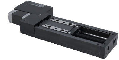
LRM Series User's Manual
Miniature, steel motorized linear stages
Disclaimer
Zaber’s products are not intended for use in any critical medical, aviation, or military applications or situations where a product's use or failure could cause personal injury, death, or damage to property. Zaber disclaims any warranty of fitness for a particular purpose. The user of this product agrees to Zaber's general terms and conditions of sale.
Precautions
Zaber's autodetect peripheral axes are designed to be used effortlessly with Zaber's line of autodetect controllers. The LRM includes onboard memory that allows Zaber's controllers to autodetect the model and set reasonable parameters. See the Protocol Manual for more information on how to modify the settings. Damage to the axis may result if the settings are not correct. To use your Zaber peripheral with a third-party controller, review the motor, sensor, and encoder specifications and pin-outs carefully.
Zaber’s motion control devices are precision instruments and must be handled with care. In particular, moving parts must be treated with care. Avoid axial loads in excess of the rated thrust load, axial and radial impact, dust and other contaminants and damage to the lead screw thread. These will reduce the performance of the device below stated specifications.
Lubrication should be limited to what's described in the procedures below; grease or oil should not be applied to any other surfaces, including the lead screw.
Care for Ground Steel Surfaces
The LRM base and carriage are constructed from steel alloys specifically chosen for their dimensional stability, wear resistance and hardness. These parts are not made from stainless steel. As such, a small amount of care is necessary to maintain the ground mounting surfaces on the base and carriage.
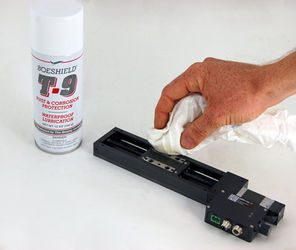
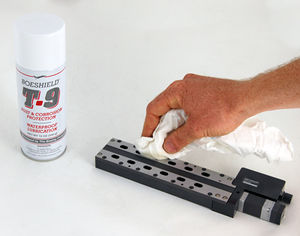
The bare steel surfaces on LRM stages are treated with Boeshield T9 corrosion protection before shipping. In our testing, this coating has proven very effective in preventing corrosion. We recommend re-applying as needed to maintain corrosion resistance. To prevent contamination of the linear bearings, spray the Boeshield onto a clean rag and wipe onto the carriage top and stage base. WD40 is an effective alternative if Boeshield is not available.
-
Wipe a thin layer of Boeshield on the carriage mounting surfaces periodically to ensure continued corrosion resistance.
-
Do the same for the base mounting surfaces.
Lubrication of Linear Guide
Many factors affect the lifetime of the grease and bearings including duty cycle, environment, travel length, stage orientation, and loading configuration. As a general guideline for usage in a clean office environment, the recommended re-lubrication interval is 250 km with an inspection after every 1500 hours of continuous operation. Inspection should be done by wiping a bearing rail with a clean, lint-free wipe and ensuring that there is clean, wetted grease present.
Harsh environment, short travel, vertically oriented, and high duty cycle applications require more frequent re-lubrication and inspection. Contact an Applications Engineer to discuss your application for more specific recommendations.
Short travel can cause an insufficient distribution of lubricant amongst the rolling elements of the bearing system. For recirculating bearing guide types, short travel is equal to or less than the length of the carriage. For crossed-roller bearing guide types, short travel is equal to or less than twice the spacing of the rolling elements (typically 5-6 mm). If your application is considered short travel, it is recommended to occasionally drive the stage throughout its full travel range to maintain an even lubrication film over the entire guide surface. More frequent re-lubrication and inspection may be required in these applications.
Contact Zaber support for relubrication kit SG133. We recommend using Shell Gadus S2 V220 2 or similar lithium thickened petroleum grease.
We recommend injecting 0.1 cm³ (1 mL) of grease into the two grease ports shown. These grease ports are located on end of the carriage facing away from the motor (see pictures below). Simply remove the set screw plugs using a 1.5 mm hex key and inject about 0.1 cm³ of grease into each port. Cycle the stage through its travel several times and wipe off any excess grease from the rails. If the grease ports shown are inaccessible, there are two alternate ports at the opposite end of the carriage that can be used instead.
All guides come pre-lubricated and are ready to go out of the box.
This grease is only intended for lubricating the ball bearing guide. It is not suitable for use on the lead screw or any other locations on the stage.
-
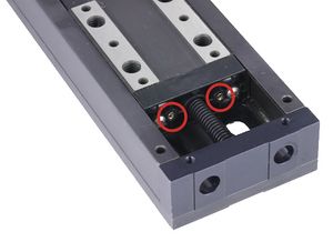
LRM linear guide lubrication ports
-
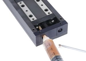
Re-lubricating LRM linear guide
Noise Emissions
The A-weighted emission sound pressure level (SPL) of this device does not exceed 70 dB(A) during intended use.
Conventions used throughout this document
- Fixed width type indicates communication to and from a device. The
 symbol indicates a carriage return, which can be achieved by pressing enter when using a terminal program.
 - An ASCII command followed by (T:xx) indicates a legacy T-Series Binary Protocol command that achieves the same result. For example,
- move abs 10000 (T:20:10000) shows that a move abs ASCII command can also be achieved with Binary command number 20.
- Not all ASCII commands have an equivalent Binary counterpart.
Device Overview
AutoDetect
Your LRM peripheral is equipped with AutoDetect, a feature that allows a Zaber controller to automatically configure its settings for the peripheral when it is connected.
 Important: The controller should always be powered down before disconnecting or connecting your LRM peripheral.
To connect the peripheral to a controller:
- Power off the controller.
- Connect the LRM peripheral.
- Power on the controller.
- The controller will activate the peripheral shortly after it is powered on.
See the Zaber controller user manual for more details on peripheral activation and control.
Connectors
Recommended controller(s) for your LRM peripheral are provided in the product specifications. Zaber's controllers and peripherals are designed for ease of use when used together. Optimal settings for each peripheral are automatically detected by Zaber's controllers when the device is connected.
For reference, the pinout for the peripheral cable connectors is shown below:
Pinout for D-sub 15 Connectors (peripherals)
| T3A Peripheral (male) | 
|
|---|---|
| T4A Peripheral (male) | 
|
| Pin # | Function |
|---|---|
| 1 | +5V for Limits & Encoder |
| 2 | AutoDetect Data |
| 3 | N.C. |
| 4 | Away Sensor |
| 5 | Home Sensor |
| 6 | Ground |
| 7 | Motor B1 |
| 8 | Motor A1 |
| 9 | AutoDetect Clock |
| 10 | Encoder A |
| 11 | Encoder B |
| 12 | Encoder Index |
| 13 | Ground |
| 14 | Motor B2 |
| 15 | Motor A2 |
Not all pins are used for all models
Alternate Controllers
The LRM can be controlled by any 2-phase stepper motor controller with limit sensor input. We do not recommend using your own controller unless you are familiar with how to control a stepper motor with hall sensor limit switches. Damage to the device due to incorrect wiring is not covered by warranty.
Motors
For motor information see the LRM product page
Limit Sensors
Hall effect sensors are used in the LRM as home sensors. The Hall sensors used are part number A1120LLHLT-T made by Allegro. Click here for data sheet. Your controller should be configured so the axis stops almost immediately (quick deceleration) when the sensors are triggered.
- PCB wire colour code:
- 5 Vdc input - red
- Home signal - yellow
- Away signal - white
- Ground - black
The Hall sensor has an open-collector output. The default output is high impedance when the Hall sensor is not active. When the sensor detects a magnet, the Hall sensor pulls the output low to ground.

If you are not using a Zaber controller, ensure that your controller has a pull-up resistor on the output line of each Hall sensor as shown in the diagram. The bypass capacitor is optional, but may help to eliminate false triggering in noisy environments. The typical value for the pull-up resistor (RLOAD) is 10 kΩ and for the bypass capacitor is 0.1 uF to 1 uF. The larger the capacitance, the better the noise filtering but the slower the response time.
Installation
Physical Installation
LRM stages can be mounted horizontally or vertically without additional hardware.
Low profile M6 (supplied) or 1/4-20 fasteners must be used. Additional fasteners can be purchased from McMaster-Carr, Fastenal, or other fastener suppliers.
-
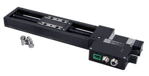
Low profile M6 or 1/4-20 mounting screws must be used.
Trajectory Control and Behaviour
This section describes the behaviour of the axis trajectory when a movement command is issued.
Software Position Limits
The travel range of the axis is limited by the Minimum Position and Maximum Position settings. The factory settings for the axis are configured to match the physical travel range. If a customized range is desired, it can be changed by configuring the limit.min (T:106) and limit.max (T:44) settings to appropriate values. For the Current Position, query pos (T:60).
- Minimum Position
- When the Current Position is less than the Minimum Position value, the axis cannot move in the negative direction(towards the motor).
- Maximum Position
- When the Current Position is greater than the Maximum Position value, the axis cannot move in the positive direction(away from the motor).
Movement Speed
The movement speed of the axis depends on axis status and various speed settings. If the axis has not been initialized by the home (T:1) command or by moving towards the home end of the axis, movement speed will be constrained to fail-safe values. The home status of the axis can be determined by reading the limit.home.triggered(T:53:103) setting.
Movement speed of the axis is specified below:
- move vel (T:22)
- The axis will move at the specified speed regardless of home status.
- Knob movement in Velocity Mode
- The axis will move at the specified speed regardless of home status.
- The speed is specified by the knob.speedprofile (T:112) and knob.maxspeed (T:111) settings.
- Other movement commands - when the axis has not been homed
- The axis will move at the slower of the maxspeed (T:42) and limit.approach.maxspeed (T:41) settings.
- Other movement commands - when the axis has been homed
- The axis will move at the speed specified by the maxspeed (T:42) setting.
Warranty and Repair
For Zaber's policies on warranty and repair, please refer to the Ordering Policies.
Standard products
Standard products are any part numbers that do not contain the suffix ENG followed by a 4 digit number. Most, but not all, standard products are listed for sale on our website. All standard Zaber products are backed by a one-month satisfaction guarantee. If you are not satisfied with your purchase, we will refund your payment minus any shipping charges. Goods must be in brand new saleable condition with no marks. Zaber products are guaranteed for one year. During this period Zaber will repair any products with faults due to manufacturing defects, free of charge.
Custom products
Custom products are any part numbers containing the suffix ENG followed by a 4 digit number. Each of these products has been designed for a custom application for a particular customer. Custom products are guaranteed for one year, unless explicitly stated otherwise. During this period Zaber will repair any products with faults due to manufacturing defects, free of charge.
How to return products
Customers with devices in need of return or repair should contact Zaber to obtain an RMA form which must be filled out and sent back to us to receive an RMA number. The RMA form contains instructions for packing and returning the device. The specified RMA number must be included on the shipment to ensure timely processing.
Email Updates
If you would like to receive our periodic email newsletter including product updates and promotions.
Contact Information
Contact Zaber Technologies Inc by any of the following methods:
| Phone | 1-604-569-3780 (direct) 1-888-276-8033 (toll free in North America) |
|---|---|
| Fax | 1-604-648-8033 |
| #2 - 605 West Kent Ave. N., Vancouver, British Columbia, Canada, V6P 6T7 | |
| Web | www.zaber.com |
| Please visit our website for up to date email contact information. |
The original instructions for this product are available at https://www.zaber.com/manuals/LRM.
Appendix A: Default Settings
Please see the Zaber Support Page for default settings for this device.
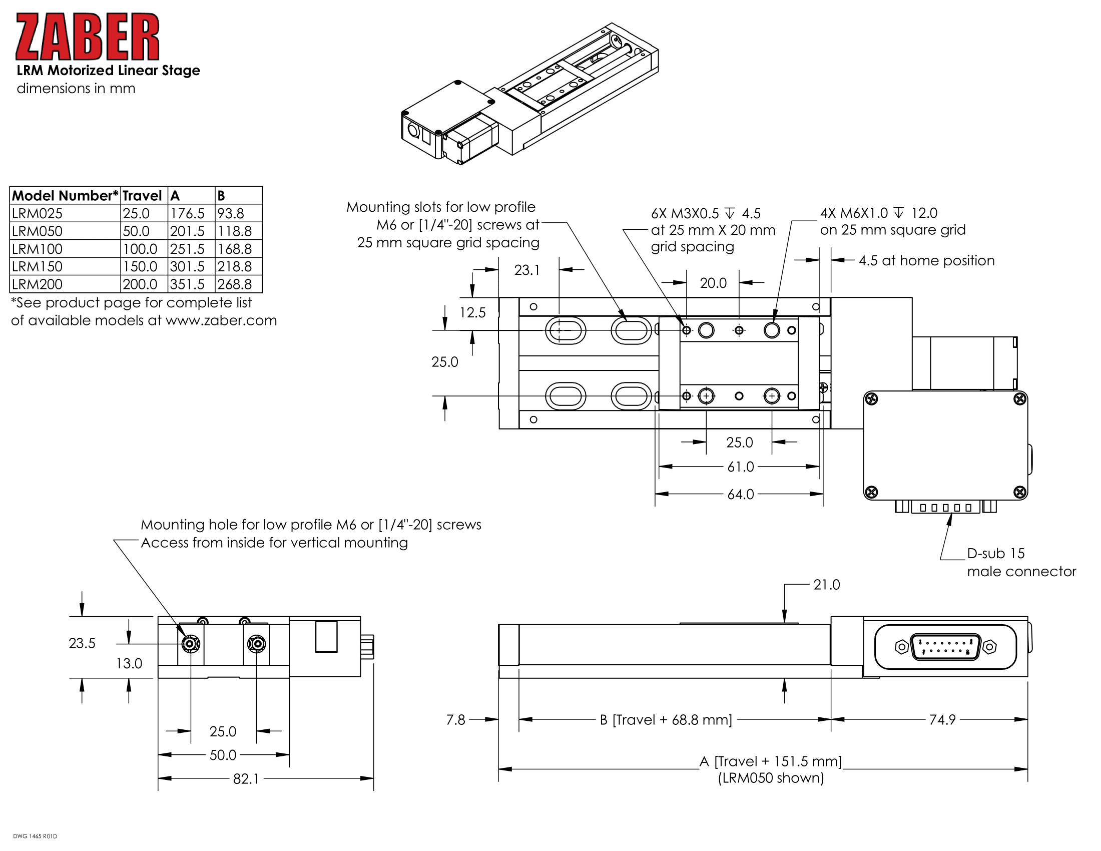
Product Drawing
Specifications
Comparison
| Part Number | Microstep Size (Default Resolution) | Travel Range | Accuracy (unidirectional) | Backlash |
|---|---|---|---|---|
| LRM025A-T3A | 0.047625 µm | 25 mm (0.984") | 8 µm (0.000315") | < 5 µm (< 0.000197") |
| LRM025B-T3A | 0.1905 µm | 25 mm (0.984") | 8 µm (0.000315") | < 12 µm (< 0.000472") |
| LRM050A-T3A | 0.047625 µm | 50 mm (1.969") | 15 µm (0.000591") | < 5 µm (< 0.000197") |
| LRM050B-T3A | 0.1905 µm | 50 mm (1.969") | 15 µm (0.000591") | < 12 µm (< 0.000472") |
| LRM100A-T3A | 0.047625 µm | 100 mm (3.937") | 30 µm (0.001181") | < 5 µm (< 0.000197") |
| LRM100B-T3A | 0.1905 µm | 100 mm (3.937") | 30 µm (0.001181") | < 12 µm (< 0.000472") |
| LRM150A-T3A | 0.047625 µm | 150 mm (5.905") | 45 µm (0.001772") | < 5 µm (< 0.000197") |
| LRM150B-T3A | 0.1905 µm | 150 mm (5.905") | 45 µm (0.001772") | < 12 µm (< 0.000472") |
| LRM200A-T3A | 0.047625 µm | 200 mm (7.874") | 60 µm (0.002362") | < 5 µm (< 0.000197") |
| LRM200B-T3A | 0.1905 µm | 200 mm (7.874") | 60 µm (0.002362") | < 12 µm (< 0.000472") |
| Part Number | Maximum Speed | Minimum Speed | Speed Resolution | Peak Thrust |
|---|---|---|---|---|
| LRM025A-T3A | 25 mm/s (0.984"/s) | 0.000029 mm/s (0.000001"/s) | 0.000029 mm/s (0.000001"/s) | 50 N (11.2 lb) |
| LRM025B-T3A | 100 mm/s (3.937"/s) | 0.000116 mm/s (0.000005"/s) | 0.000116 mm/s (0.000005"/s) | 25 N (5.6 lb) |
| LRM050A-T3A | 25 mm/s (0.984"/s) | 0.000029 mm/s (0.000001"/s) | 0.000029 mm/s (0.000001"/s) | 50 N (11.2 lb) |
| LRM050B-T3A | 100 mm/s (3.937"/s) | 0.000116 mm/s (0.000005"/s) | 0.000116 mm/s (0.000005"/s) | 25 N (5.6 lb) |
| LRM100A-T3A | 25 mm/s (0.984"/s) | 0.000029 mm/s (0.000001"/s) | 0.000029 mm/s (0.000001"/s) | 50 N (11.2 lb) |
| LRM100B-T3A | 100 mm/s (3.937"/s) | 0.000116 mm/s (0.000005"/s) | 0.000116 mm/s (0.000005"/s) | 25 N (5.6 lb) |
| LRM150A-T3A | 25 mm/s (0.984"/s) | 0.000029 mm/s (0.000001"/s) | 0.000029 mm/s (0.000001"/s) | 50 N (11.2 lb) |
| LRM150B-T3A | 100 mm/s (3.937"/s) | 0.000116 mm/s (0.000005"/s) | 0.000116 mm/s (0.000005"/s) | 25 N (5.6 lb) |
| LRM200A-T3A | 25 mm/s (0.984"/s) | 0.000029 mm/s (0.000001"/s) | 0.000029 mm/s (0.000001"/s) | 50 N (11.2 lb) |
| LRM200B-T3A | 100 mm/s (3.937"/s) | 0.000116 mm/s (0.000005"/s) | 0.000116 mm/s (0.000005"/s) | 25 N (5.6 lb) |
| Part Number | Linear Motion Per Motor Rev | Weight |
|---|---|---|
| LRM025A-T3A | 0.6096 mm (0.024") | 0.71 kg (1.565 lb) |
| LRM025B-T3A | 2.4384 mm (0.096") | 0.71 kg (1.565 lb) |
| LRM050A-T3A | 0.6096 mm (0.024") | 0.79 kg (1.742 lb) |
| LRM050B-T3A | 2.4384 mm (0.096") | 0.79 kg (1.742 lb) |
| LRM100A-T3A | 0.6096 mm (0.024") | 0.95 kg (2.094 lb) |
| LRM100B-T3A | 2.4384 mm (0.096") | 0.95 kg (2.094 lb) |
| LRM150A-T3A | 0.6096 mm (0.024") | 1.11 kg (2.447 lb) |
| LRM150B-T3A | 2.4384 mm (0.096") | 1.11 kg (2.447 lb) |
| LRM200A-T3A | 0.6096 mm (0.024") | 1.29 kg (2.844 lb) |
| LRM200B-T3A | 2.4384 mm (0.096") | 1.29 kg (2.844 lb) |
Charts and Notes
Product Change Notices
Click here to view the current product change notices and subscribe to future change notifications.