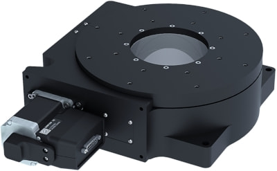
RST240-E Series User's Manual
RST240-E
Disclaimer
Zaber’s products are not intended for use in any critical medical, aviation, or military applications or situations where a product's use or failure could cause personal injury, death, or damage to property. Zaber disclaims any warranty of fitness for a particular purpose. The user of this product agrees to Zaber's general terms and conditions of sale.
Precautions
Zaber's autodetect peripheral axes are designed to be used effortlessly with Zaber's line of autodetect controllers. The RST240-E includes onboard memory that allows Zaber's controllers to autodetect the model and set reasonable parameters. See the Protocol Manual for more information on how to modify the settings. Damage to the axis may result if the settings are not correct. To use your Zaber peripheral with a third-party controller, review the motor, sensor, and encoder specifications and pin-outs carefully.
Noise Emissions
The A-weighted emission sound pressure level (SPL) of this device does not exceed 70 dB(A) during intended use.
Payload Caution

This image shows a RST240-E with varying payloads to demonstrate the relative size of large payloads that meet the maximum angular momentum specification of 1.6kg-m²/s when rotated at the angular speeds listed below. The size of these solid cylindrical payloads was determined using the density of steel of 8,000 kg/m³. The maximum allowable rotational speed of the 300kg load is 12°/s or 2 RPM. The rated maximum speed of the device of 60°/s can be safely met with a 125kg payload, or less. It is important to determine the moment of inertia of your payload. In the event of a sudden stall from high speeds, higher inertia payloads will impart large forces through the drivetrain of the RST240-E, resulting in possible damage.
The below table lists the maximum allowable speed a particular payload can be rotated at, in order to not exceed the maximum angular momentum of 1.6 kg-m²/s for the RST240-E.
| Payload, m [kg] | Example Inertia, I [kg-m²] | Maximum Allowable Speed, [°/s] |
|---|---|---|
| 50 | 0.21 | 60 |
| 100 | 0.85 | 60 |
| 150 | 1.89 | 48 |
| 200 | 3.39 | 27 |
| 250 | 5.28 | 17 |
| 300 | 7.58 | 12 |
Conventions used throughout this document
- Fixed width type indicates communication to and from a device. The
 symbol indicates a carriage return, which can be achieved by pressing enter when using a terminal program.
 - An ASCII command followed by (T:xx) indicates a legacy T-Series Binary Protocol command that achieves the same result. For example,
- move abs 10000 (T:20:10000) shows that a move abs ASCII command can also be achieved with Binary command number 20.
- Not all ASCII commands have an equivalent Binary counterpart.
Device Overview
AutoDetect
Your RST240-E peripheral is equipped with AutoDetect, a feature that allows a Zaber controller to automatically configure its settings for the peripheral when it is connected.
 Important: The controller should always be powered down before disconnecting or connecting your RST240-E peripheral.
To connect the peripheral to a controller:
- Power off the controller.
- Connect the RST240-E peripheral.
- Power on the controller.
- The controller will activate the peripheral shortly after it is powered on.
See the Zaber controller user manual for more details on peripheral activation and control.
Connectors
Recommended controller(s) for your RST240-E peripheral are provided in the product specifications. Zaber's controllers and peripherals are designed for ease of use when used together. Optimal settings for each peripheral are automatically detected by Zaber's controllers when the device is connected.
For reference, the pinout for the peripheral cable connectors is shown below:
Pinout for D-sub 15 Connectors (peripherals)
| T3A Peripheral (male) | 
|
|---|---|
| T4A Peripheral (male) | 
|
| Pin # | Function |
|---|---|
| 1 | +5V for Limits & Encoder |
| 2 | AutoDetect Data |
| 3 | N.C. |
| 4 | Away Sensor |
| 5 | Home Sensor |
| 6 | Ground |
| 7 | Motor B1 |
| 8 | Motor A1 |
| 9 | AutoDetect Clock |
| 10 | Encoder A |
| 11 | Encoder B |
| 12 | Encoder Index |
| 13 | Ground |
| 14 | Motor B2 |
| 15 | Motor A2 |
Not all pins are used for all models
Alternate Controllers
The RST240-E can be controlled by any 2-phase stepper motor controller with limit sensor and appropriate encoder input. We do not recommend using your own controller unless you are familiar with how to control a stepper motor with encoders and hall sensor limit switches. Damage to the device due to incorrect wiring is not covered by warranty.
Motors & Encoders
For motor and encoder information see the RST240-E product page
Limit Sensors
Hall effect sensors are used in the RST240-E as home sensors. The Hall sensors used are part number A1120LLHLT-T made by Allegro. Click here for data sheet. Your controller should be configured so the axis stops almost immediately (quick deceleration) when the sensors are triggered.
- PCB wire colour code:
- 5 Vdc input - red
- Home signal - yellow
- Away signal - white
- Ground - black
The Hall sensor has an open-collector output. The default output is high impedance when the Hall sensor is not active. When the sensor detects a magnet, the Hall sensor pulls the output low to ground.

If you are not using a Zaber controller, ensure that your controller has a pull-up resistor on the output line of each Hall sensor as shown in the diagram. The bypass capacitor is optional, but may help to eliminate false triggering in noisy environments. The typical value for the pull-up resistor (RLOAD) is 10 kΩ and for the bypass capacitor is 0.1 uF to 1 uF. The larger the capacitance, the better the noise filtering but the slower the response time.
Installation
Mounting
Secure the RST240-E with 4 M8 (or 5/16"-18) socket cap screws, 40 mm or longer, by the 5 M8 mounting holes on the bottom flanges of the stage. There are also M6 threaded holes on the side of the stage available for mounting purposes. See the RST240 web page for dimensions, technical specifications and other details.
Maintenance
RST240-E devices use precision worm gears for rotary motion. To insure long service life and the highest performance, it is necessary to keep the worm gear mesh lubricated.
The worm gear should be re-greased after the first 200 hours of operation and every 1000 hours of operation thereafter. Many factors affect the re-lubrication interval including temperature, contamination, and load. Inspect device for noise or vibration and re-lubricate based on inspection results. At high torque loads, the re-lubrication interval will be shortened, inspect the device more frequently depending on application.
Lubrication
Temporarily remove power to the device before attempting to lubricate. Remove any payloads from the device stage top if they pose tipping, crushing, pinching and/or other hazards.
Slowly rotate stage (<5 RPM) while adding 7.5 cc's of lubricant into the grease fitting. The stage should complete a full revolution before all 7.5 cc's of lubricant are added. It is recommended to rotate the stage 10 revolutions clockwise and counterclockwise to distribute the grease. Grease with DuPont Molykote® G-4700 or similar viscosity synthetic NLGI Grade 2 lithium thickened grease with solid lubricants. All devices come pre-lubricated and are ready to go out of the box.
If RST240-E devices are used in applications where only a small angular portion of the rotational travel range is used, occasionally rotate the stage throughout its full travel to maintain an even lubrication film over the entire worm gear and redistribute the lubrication in the bearings.
-

1. Locate the grease fitting cover on the bottom of the device.
-

2. Remove the 5x M2.5 screws. Lift the cover plate out with a dull flat bladed tool.
-

3. Leave the 3x o-rings in place.
-

4. Wipe fitting clean. Add new lubricant through the grease fitting, wipe off excess. Reinstall the cover plate removed in step 2 with the 5x M2.5 screws.
Lubrication Precautions
The seals in the device can be damaged with excessive lubrication pressure levels or lubricant quantities. Slowly add lubricant to avoid over pressurizing internal cavity. Damage can be caused by using the wrong grease.
Trajectory Control and Behaviour
This section describes the behaviour of the axis trajectory when a movement command is issued.
Software Position Limits
The travel range of the axis is limited by the Minimum Position and Maximum Position settings. The factory settings for the axis are configured to match the physical travel range. If a customized range is desired, it can be changed by configuring the limit.min (T:106) and limit.max (T:44) settings to appropriate values. For the Current Position, query pos (T:60).
- Minimum Position
- When the Current Position is less than the Minimum Position value, the axis cannot move in the negative direction(towards the motor).
- Maximum Position
- When the Current Position is greater than the Maximum Position value, the axis cannot move in the positive direction(away from the motor).
Movement Speed
The movement speed of the axis depends on axis status and various speed settings. If the axis has not been initialized by the home (T:1) command or by moving towards the home end of the axis, movement speed will be constrained to fail-safe values. The home status of the axis can be determined by reading the limit.home.triggered(T:53:103) setting.
Movement speed of the axis is specified below:
- move vel (T:22)
- The axis will move at the specified speed regardless of home status.
- Knob movement in Velocity Mode
- The axis will move at the specified speed regardless of home status.
- The speed is specified by the knob.speedprofile (T:112) and knob.maxspeed (T:111) settings.
- Other movement commands - when the axis has not been homed
- The axis will move at the slower of the maxspeed (T:42) and limit.approach.maxspeed (T:41) settings.
- Other movement commands - when the axis has been homed
- The axis will move at the speed specified by the maxspeed (T:42) setting.
Warranty and Repair
For Zaber's policies on warranty and repair, please refer to the Ordering Policies.
Standard products
Standard products are any part numbers that do not contain the suffix ENG followed by a 4 digit number. Most, but not all, standard products are listed for sale on our website. All standard Zaber products are backed by a one-month satisfaction guarantee. If you are not satisfied with your purchase, we will refund your payment minus any shipping charges. Goods must be in brand new saleable condition with no marks. Zaber products are guaranteed for one year. During this period Zaber will repair any products with faults due to manufacturing defects, free of charge.
Custom products
Custom products are any part numbers containing the suffix ENG followed by a 4 digit number. Each of these products has been designed for a custom application for a particular customer. Custom products are guaranteed for one year, unless explicitly stated otherwise. During this period Zaber will repair any products with faults due to manufacturing defects, free of charge.
How to return products
Customers with devices in need of return or repair should contact Zaber to obtain an RMA form which must be filled out and sent back to us to receive an RMA number. The RMA form contains instructions for packing and returning the device. The specified RMA number must be included on the shipment to ensure timely processing.
Email Updates
If you would like to receive our periodic email newsletter including product updates and promotions.
Contact Information
Contact Zaber Technologies Inc by any of the following methods:
| Phone | 1-604-569-3780 (direct) 1-888-276-8033 (toll free in North America) |
|---|---|
| Fax | 1-604-648-8033 |
| #2 - 605 West Kent Ave. N., Vancouver, British Columbia, Canada, V6P 6T7 | |
| Web | www.zaber.com |
| Please visit our website for up to date email contact information. |
The original instructions for this product are available at https://www.zaber.com/manuals/RST240-E.
Appendix A: Default Settings
Please see the Zaber Support Page for default settings for this device.
Product Drawing
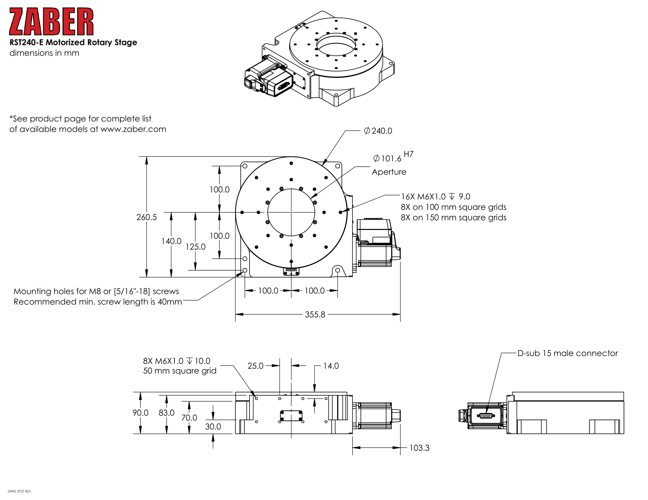
Specifications
| Specification | Value | Alternate Unit |
|---|---|---|
| Microstep Size (Default Resolution) | 0.00027574° | 4.812 µrad |
| Built-in Controller | No | |
| Recommended Controller | MCC (48 V) Recommended | |
| AutoDetect | Yes | |
| Range | 360° | |
| Accuracy (unidirectional) | 0.075° | 1.308750 mrad |
| Repeatability | < 0.0015° | < 0.026 mrad |
| Backlash | < 0.05° | < 0.873 mrad |
| Maximum Speed | 60°/s | 10 rpm |
| Minimum Speed | 0.000168°/s | 2.932 µrad/s |
| Speed Resolution | 0.000168°/s | 2.932 µrad/s |
| Encoder Resolution | 400 CPR | 1600 states/rev |
| Encoder Type | Rotary quadrature encoder (incremental) | |
| Maximum Torque | 7000 N⋅cm | 9912.8 oz⋅in |
| Maximum Continuous Torque | 4500 N⋅cm | 6372.5 oz⋅in |
| Maximum Centered Load | 3000 N | 672.8 lb |
| Maximum Moment (Tilt) | 20000 N⋅cm | 28322.4 oz⋅in |
| Stage Top Dimension | 240 mm | 9.449" |
| Radial Error Motion | +/- 2.5 µm | +/- 0.000098" |
| Axial Error Motion | < 4 µm | < 0.000157" |
| Tilt Error Motion | +/- 0.003° | +/- 52.36 µrad |
| Bearing Plane Offset | 30.75 mm | 1.211" |
| Stiffness (Tilt) | 8000 N⋅m/° | 2.2 µrad/N⋅m |
| Angular Motion Per Motor Rev | 3.5294° | |
| Motor Steps Per Rev | 200 | |
| Motor Type | Stepper (2 phase) | |
| Motor Rated Current | 3000 mA/phase | |
| Motor Winding Resistance | 0.53 ohms/phase | |
| Motor Winding Inductance | 2 mH/phase | |
| Motor Connection | D-sub 15 | |
| Default Resolution | 1/64 of a step | |
| Maximum Angular Momentum | 1.6 kg⋅m2/s | |
| Motor Frame Size | 23 | |
| Guide Type | Crossed-Roller Bearing | |
| Mechanical Drive System | Precision Worm Gear | |
| Limit or Home Sensing | Magnetic home sensor | |
| Gear Ratio | 102:1 | |
| Mounting Interface | M6 threaded holes and M8 mounting holes | |
| Operating Temperature Range | 0-50 °C | |
| CE Compliant | Yes | |
| Vacuum Compatible | No | |
| Weight | 14.5 kg | 31.967 lb |
Charts and Notes
Product Change Notices
Click here to view the current product change notices and subscribe to future change notifications.