LC40C Series User's Manual
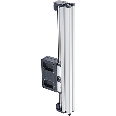
Belt-driven T-slot cantilever axis, motor-ready
Disclaimer
Zaber’s products are not intended for use in any critical medical, aviation, or military applications or situations where a product's use or failure could cause personal injury, death, or damage to property. Zaber disclaims any warranty of fitness for a particular purpose. The user of this product agrees to Zaber's general terms and conditions of sale.
Precautions
 Pinch Hazard: Keep hands away from the moving carriage. Use caution when mounting components near the path of the carriage; they may create unexpected pinch hazards.
Backdriving: If motor power is suddenly lost, any vertical loads may fall quickly or high inertial loads may fail to stop. This may cause personal injury or damage to the payload, the device, or to electronics. This device is not recommended for vertical lifting applications with loads greater than 1 kg.
 Important: Mounting large objects to the carriage or using this component in a multi-axis system may create new or unexpected risks. Always perform a risk analysis for your complete system in its operating environment.
Device Overview
Motor Options
The LC40C series of belt-driven linear guides can be paired with Zaber motor kits.
KM03
Motor kit KM03 has an integrated controller for single axis control and includes:
- X-NMS23-E08P1 motor with integrated controller and encoder
- AC183 pulley coupling
- AP265 home sensor mount and magnet
KM03B
Motor kit KM03B has an integrated controller with a power-off brake for single axis control and includes:
- X-NMS23-BE08P1 motor with integrated controller, encoder, and power-off brake
- AC183 pulley coupling
- AP265 home sensor mount and magnet
KM04
Motor kit KM04 is intended for use with a external Zaber controller and includes:
- NMS23-E08P1T3A motor with an encoder
- AC183 pulley coupling
- AP265 home sensor mount and magnet
KM04B
Motor kit KM04B is intended for use with a external Zaber controller and includes:
- NMS23-BE08P1T10A motor with an encoder and power-off brake
- AC183 pulley coupling
- AP265 home sensor mount and magnet
Third Party Motors
In addition to Zaber motors, any NEMA 23 frame size motor can be mounted to either side of the pulley drive. NEMA 17 frame size motors may be mounted using the AP192 motor adaptor. Make sure to match the motor shaft diameter to the appropriate pulley coupling diameter:
- AC183 pulley coupling for 8 mm shaft
- AC184 pulley coupling for 6.35 mm shaft
- AC185 pulley coupling for 5 mm shaft
T-Slot Compatibility
The LC40 linear guide system is designed to be compatible with most common 40 mm T-slot extrusion framing systems. The two main requirements for compatibility are a 40 mm square profile width and an 8 mm slot width. While we have not exhaustively tested all systems and components, the following framing systems meet this basic compatibility requirements:
- 80/20 40 Series
- McMaster Carr 40 mm
- Parker-Hannifin 40 Series
- item Profile 8
- Parco 40 Series
- TSLOTS T40

Beam Properties
The LC40 linear guide is intended to also function as a structural member, similar to other aluminum extrusion framing systems.
- Material: 6063-T65 anodized aluminum extrusion
- Straightness Tolerance: 0.7 mm/m
- Yield Strength: 230 MPa
- Modulus of Elasticity: 68900 MPa
- Mass per Length: 2.35 kg/m
- Flexural Rigidity (EI): 13300 Nm²
Installation and Setup
Required Tools
- 2 mm hex key
- 3 mm hex key
- 5 mm hex key
Motor Kit Installation
Note: X-NMS23-E08P1 motor is shown in the images below. The instructions are applicable for both X-NMS23-(B)E08P1 (motor with integrated controller) and NMS23-(B)E08P1T3A (motor without controller).

- Mount the clamping pulley coupling (AC183) flush to the end of the motor shaft. Tighten the coupling to the motor shaft using a 2 mm hex key.
- Insert the motor with coupling into the pulley bore of the LC40C linear guide. The motor can mount on either side, and the motor housing may point in any direction. The plastic covers over the pulley bore can be pried out with a 3 mm hex key. Secure the motor with M4 fasteners and 3 mm hex key.
- Fasten the home sensor (included with motor) to the AP265 limit sensor bracket using a 2 mm hex key.
- Install an M6 T-nut into the side of the LC40C linear guide for the AP265 limit sensor magnet. The home sensor and magnet may be mounted to either side of the LC40C, but for easy wire routing it is recommended to mount it on the same side as the motor.
- Attach the AP265 magnet to the T-nut using an M6 fastener and 5 mm hex key. Attach the AP265 limit sensor bracket with home sensor with M3 countersink fasteners using a 2 mm hex key onto the side of the LC40C carriage. Route the cable through the slot on the back of the limit sensor bracket. The bracket should be on the end of the carriage towards the home direction with the cable pointing toward the motor.
- Set the magnet position to approximately 58 mm from the end of the extrusion.
Please use the LC40 Setup Application within Zaber Launcher to help configure the LC40C.
The app will perform a test that moves the stage through the full travel range. Ensure the stage is securely mounted before performing this step.
The motor controller can also be set up manually via the following steps if you choose not to use the LC40 Setup Application:
- If your drive kit is installed in a left-hand orientation, it will function right away. If the drive is installed in a right-hand orientation, the travel direction will need to be reversed in the controller settings. These commands can be executed with the following commands sent through the terminal in Zaber Launcher:
- set system.access 2
- set driver.dir 0
- set encoder.dir 1
- set system.access 1
- Set the maximum travel setting (limit.max) to match the physical travel of the device. The travel in mm can be found from the 4 digits following LC40C on the product part number.
- For example, part number 'LC40C0450' has a travel of 450 mm. This travel should be multiplied by 142.222 to convert it to microsteps (rounded to an integer) and sent through the terminal as the command "set limit.max 64000"
Maintenance
Many factors affect the lifetime of the grease and bearings including duty cycle, environment, travel length, stage orientation, and loading configuration. As a general guideline for usage in a clean office environment, the recommended re-lubrication interval is 250 km with an inspection after every 1500 hours of continuous operation. Inspection should be done by wiping a bearing rail with a clean, lint-free wipe and ensuring that there is clean, wetted grease present.
Harsh environment, short travel, vertically oriented, and high duty cycle applications require more frequent re-lubrication and inspection. Contact an Applications Engineer to discuss your application for more specific recommendations.
Short travel can cause an insufficient distribution of lubricant amongst the rolling elements of the bearing system. For recirculating bearing guide types, short travel is equal to or less than the length of the carriage. For crossed-roller bearing guide types, short travel is equal to or less than twice the spacing of the rolling elements (typically 5-6 mm). If your application is considered short travel, it is recommended to occasionally drive the stage throughout its full travel range to maintain an even lubrication film over the entire guide surface. More frequent re-lubrication and inspection may be required in these applications.
Contact Zaber support for relubrication kit SG133. We recommend using Shell Gadus S2 V220 2 or similar lithium thickened petroleum grease.
Relubrication Procedure
Contact Zaber support for relubrication kit SG133.
-
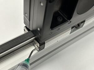
Insert angled syringe tip into grease hole in bearing end cap. Move the carriage about 50 mm while squeezing approximately 0.2 mL of grease from the syringe. Repeat for all eight end caps. Cycle the carriage through the full range of travel.
Load Capacity
Vertical Operation
It is strongly recommended that a power-off brake be used for all vertical configurations to prevent the column and payload from dropping when powering off the device and in the event of motor stalls or other faults.
The maximum recommended static vertical load is 7 kg to remain within the capacity of both the motor and the power-off brake. This load should account for the moving mass and the attached payload, as provided in the specifications. For heavier loads, it may be necessary to increase the run current and hold current settings and reduce the maximum speed and acceleration settings.
Horizontal Operation
When using the stage as a horizontal cantilever axis, the maximum moment applied to the bearings including the weight of the extrusion must not exceed the maximum moment specification for the stage. The weight of the extrusion is given by the moving mass specification with the center of gravity located at the center of the extrusion.
It is preferable for the primary direction of applied moments to be in pitch rather than yaw.
Warranty and Repair
For Zaber's policies on warranty and repair, please refer to the Ordering Policies.
Standard products
Standard products are any part numbers that do not contain the suffix ENG followed by a 4 digit number. Most, but not all, standard products are listed for sale on our website. All standard Zaber products are backed by a one-month satisfaction guarantee. If you are not satisfied with your purchase, we will refund your payment minus any shipping charges. Goods must be in brand new saleable condition with no marks. Zaber products are guaranteed for one year. During this period Zaber will repair any products with faults due to manufacturing defects, free of charge.
Custom products
Custom products are any part numbers containing the suffix ENG followed by a 4 digit number. Each of these products has been designed for a custom application for a particular customer. Custom products are guaranteed for one year, unless explicitly stated otherwise. During this period Zaber will repair any products with faults due to manufacturing defects, free of charge.
How to return products
Customers with devices in need of return or repair should contact Zaber to obtain an RMA form which must be filled out and sent back to us to receive an RMA number. The RMA form contains instructions for packing and returning the device. The specified RMA number must be included on the shipment to ensure timely processing.
Email Updates
If you would like to receive our periodic email newsletter including product updates and promotions.
Contact Information
Contact Zaber Technologies Inc by any of the following methods:
| Phone | 1-604-569-3780 (direct) 1-888-276-8033 (toll free in North America) |
|---|---|
| Fax | 1-604-648-8033 |
| #2 - 605 West Kent Ave. N., Vancouver, British Columbia, Canada, V6P 6T7 | |
| Web | www.zaber.com |
| Please visit our website for up to date email contact information. |
The original instructions for this product are available at https://www.zaber.com/manuals/LC40C.
Appendix A: Accessories
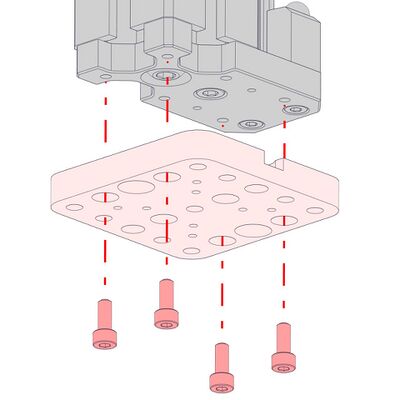
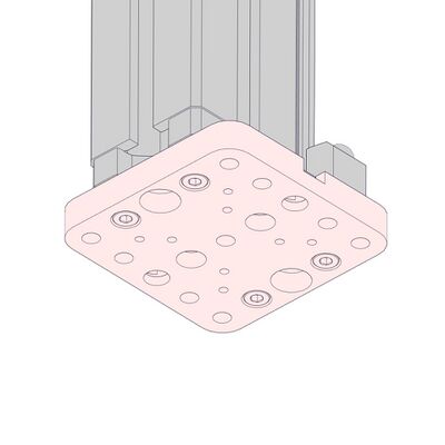
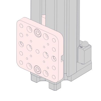
AP266 Mounting Plate
 |
This mounting plate attaches to the pulley housing of the LC40C and allows the device to be mounted to various Zaber devices and Gantry systems or any 25 mm x 25 mm M6 grid. This mounting plate is suitable for vertical and horizontal mounting.
-
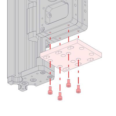
Attach the AP266 mounting plate to the LC40C pulley housing with 4 x M4 x 8 screws.
-
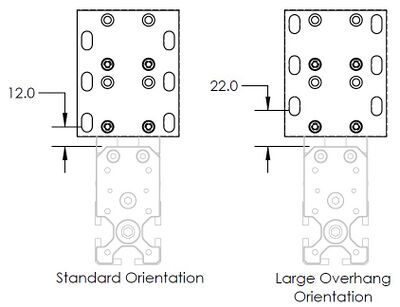
For vertical mounting, the mounting plate can be reversed to increase the amount of overhang which may be necessary in some cases for the extrusion to clear the platform it is mounted to.
Cable Guides
CG01
 |
 |
CG01 can mount directly to the stage in line with the extrusion without additional mounting plates. This option works well for single cables and makes it easy to pass cables directly into the t-slots.

-
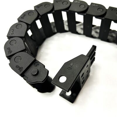
Attach the CG01T mating end with the through holes pivoted 90° as shown. The end should be pointing inwards towards the cable guide bend.
-
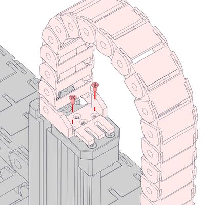
Attach the end of the cable guide with the rotated termination to the end plate of the column with 2 x M3 countersink screws.
-
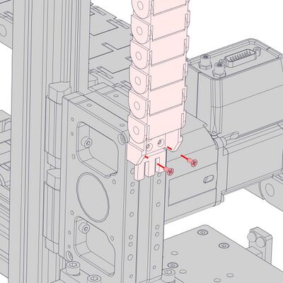
Attach the other end to the pulley housing with 2 x M3 countersink screws.
-
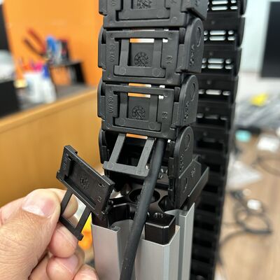
After attaching the cable guide to the end plate remove as many covers from the links as necessary for the cable to freely exit the cable guide.
-
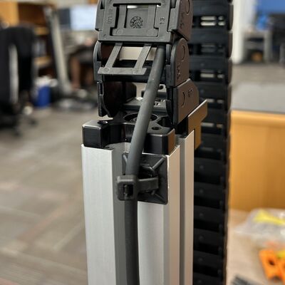
Use adhesive-backed cable tie mounts (provided in the CGxxT kit) to secure cables to a surface near the exit of the cable guide.
CG02 and Other Cable Guides
 |
 |
 |
 |
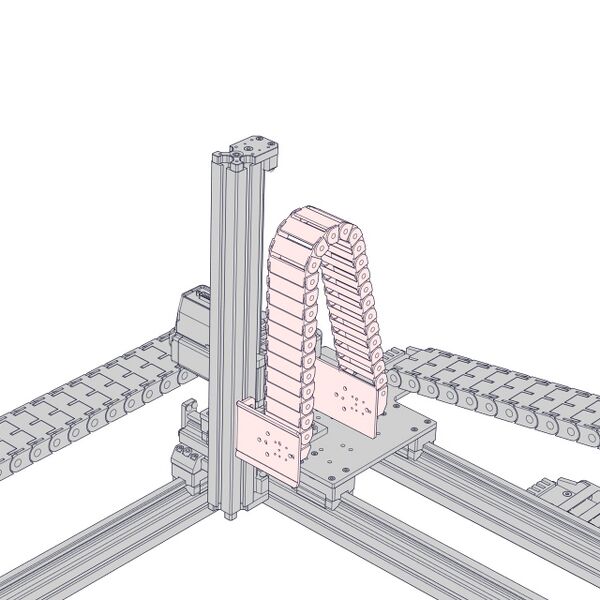
AP235 and AP238 can be used to mount CG02 and other cable guide options to the side of the column. This solution works well for managing multiple cables.
-

Install 2 x roll-in T-nuts into the side of the Z-axis stage you intend to mount the cable guide beside.
-
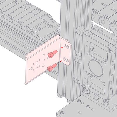
Install the AP235 support using 2 x M6 x 14 screws and the 5 mm hex key. Slide the support along the extrusion to the desired locations, then tighten the fasteners.
-
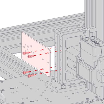
Attach the AP238 plate to the Z-axis pulley housing using the provided M4 x 8 screws and the 3 mm hex key.
-
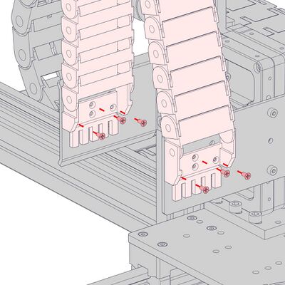
Install the cable guide by attaching the terminations to the AP235 and AP238 supports. Check that the stage can reach both ends of travel. If it does not, adjust the positions of the AP235 support as needed.
AP191 LC40 Adaptor Plate
 |
These adaptor plates attach to either the t-slots or the end plate of the LC40C to provide an M6 and M3 mounting pattern.
Attaching to End Plate
-
Attach the AP191 adaptor plate using 4 x M4 x 10 screws.
-
Attaching to T-slots
-
Install 2 x roll-in T-nuts into the T-slot.
-
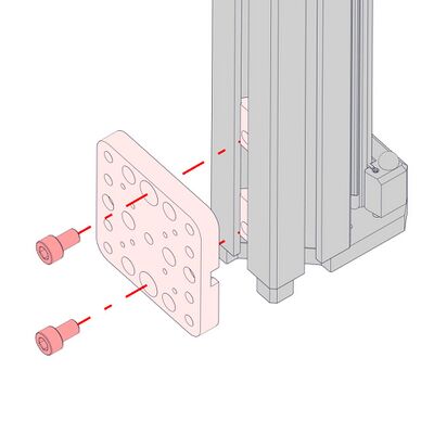
Attach the AP191 adaptor plate using 2 x M6 x 10 screws.
-
Product Drawing
Specifications
| Specification | Value | Alternate Unit |
|---|---|---|
| Maximum Centered Load | 1000 N | 224.3 lb |
| Maximum Moment (Pitch) | 80 N⋅m | 59.0 lb⋅ft |
| Maximum Moment (Roll) | 12 N⋅m | 8.9 lb⋅ft |
| Maximum Moment (Yaw) | 60 N⋅m | 44.3 lb⋅ft |
| Stiffness (Pitch) | 3170 N⋅m/° | 6 µrad/N⋅m |
| Stiffness (Roll) | 48 N⋅m/° | 364 µrad/N⋅m |
| Stiffness (Yaw) | 750 N⋅m/° | 23 µrad/N⋅m |
| Linear Motion Per Motor Rev | 90 mm | 3.543" |
| Guide Type | Recirculating Ball Linear Guide | |
| Mechanical Drive System | Synchronous belt | |
| Axes of Motion | 1 | |
| Operating Temperature Range | 0 to 50 °C | |
| CE Compliant | Yes | |
| Vacuum Compatible | No |
Comparison
| Part Number | Travel Range | Moving Mass | Weight |
|---|---|---|---|
| LC40C0100 | 100 mm (3.937") | 1.01 kg (2.222 lbs) | 1.947 kg (4.292 lb) |
| LC40C0150 | 150 mm (5.905") | 1.13 kg (2.486 lbs) | 2.066 kg (4.555 lb) |
| LC40C0200 | 200 mm (7.874") | 1.25 kg (2.750 lbs) | 2.186 kg (4.819 lb) |
| LC40C0250 | 250 mm (9.843") | 1.37 kg (3.014 lbs) | 2.305 kg (5.082 lb) |
| LC40C0300 | 300 mm (11.811") | 1.49 kg (3.278 lbs) | 2.424 kg (5.344 lb) |
| LC40C0350 | 350 mm (13.780") | 1.61 kg (3.542 lbs) | 2.544 kg (5.609 lb) |
| LC40C0400 | 400 mm (15.748") | 1.73 kg (3.806 lbs) | 2.663 kg (5.871 lb) |
| LC40C0450 | 450 mm (17.716") | 1.85 kg (4.070 lbs) | 2.783 kg (6.135 lb) |
| LC40C0500 | 500 mm (19.685") | 1.97 kg (4.334 lbs) | 2.902 kg (6.398 lb) |
Product Change Notices
Click here to view the current product change notices and subscribe to future change notifications.
This product uses the FreeRTOS kernel. FreeRTOS is © 2026 Amazon.com, Inc. or its affiliates and is governed by the following license:
All rights reserved.
Permission is hereby granted, free of charge, to any person obtaining a copy of this software and associated documentation files (the "Software"), to deal in the Software without restriction, including without limitation the rights to use, copy, modify, merge, publish, distribute, sublicense, and/or sell copies of the Software, and to permit persons to whom the Software is furnished to do so, subject to the following conditions:
The above copyright notice and this permission notice shall be included in all copies or substantial portions of the Software.
THE SOFTWARE IS PROVIDED "AS IS", WITHOUT WARRANTY OF ANY KIND, EXPRESS OR IMPLIED, INCLUDING BUT NOT LIMITED TO THE WARRANTIES OF MERCHANTABILITY, FITNESS FOR A PARTICULAR PURPOSE AND NONINFRINGEMENT.
IN NO EVENT SHALL THE AUTHORS OR COPYRIGHT HOLDERS BE LIABLE FOR ANY CLAIM, DAMAGES OR OTHER LIABILITY, WHETHER IN AN ACTION OF CONTRACT, TORT OR OTHERWISE, ARISING FROM, OUT OF OR IN CONNECTION WITH THE SOFTWARE OR THE USE OR OTHER DEALINGS IN THE SOFTWARE.
This product uses the LZ4 compression library. LZ4 is © 2011–2016 Yann Collet and is governed by the following license:
All rights reserved.
Redistribution and use in source and binary forms, with or without modification, are permitted provided that the following conditions are met:
- Redistributions of source code must retain the above copyright notice, this list of conditions and the following disclaimer.
- Redistributions in binary form must reproduce the above copyright notice, this list of conditions and the following disclaimer in the documentation and/or other materials provided with the distribution.
THIS SOFTWARE IS PROVIDED BY THE COPYRIGHT HOLDERS AND CONTRIBUTORS "AS IS" AND ANY EXPRESS OR IMPLIED WARRANTIES, INCLUDING, BUT NOT LIMITED TO, THE IMPLIED WARRANTIES OF MERCHANTABILITY AND FITNESS FOR A PARTICULAR PURPOSE ARE DISCLAIMED. IN NO EVENT SHALL THE COPYRIGHT HOLDER OR CONTRIBUTORS BE LIABLE FOR ANY DIRECT, INDIRECT, INCIDENTAL, SPECIAL, EXEMPLARY, OR CONSEQUENTIAL DAMAGES (INCLUDING, BUT NOT LIMITED TO, PROCUREMENT OF SUBSTITUTE GOODS OR SERVICES; LOSS OF USE, DATA, OR PROFITS; OR BUSINESS INTERRUPTION) HOWEVER CAUSED AND ON ANY THEORY OF LIABILITY, WHETHER IN CONTRACT, STRICT LIABILITY, OR TORT (INCLUDING NEGLIGENCE OR OTHERWISE) ARISING IN ANY WAY OUT OF THE USE OF THIS SOFTWARE, EVEN IF ADVISED OF THE POSSIBILITY OF SUCH DAMAGE.