BLQ-EC Series User's Manual
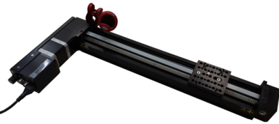
Motorized linear stages with built-in motor encoders and covers
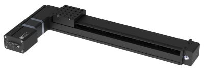
Table of Contents
Table of Contents
Disclaimer
Zaber’s products are not intended for use in any critical medical, aviation, or military applications or situations where a product's use or failure could cause personal injury, death, or damage to property. Zaber disclaims any warranty of fitness for a particular purpose. The user of this product agrees to Zaber's general terms and conditions of sale.
Precautions
Zaber's autodetect peripheral axes are designed to be used effortlessly with Zaber's line of autodetect controllers. The BLQ-EC includes onboard memory that allows Zaber's controllers to autodetect the model and set reasonable parameters. See the Protocol Manual for more information on how to modify the settings. Damage to the axis may result if the settings are not correct. To use your Zaber peripheral with a third-party controller, review the motor, sensor, and encoder specifications and pin-outs carefully.
Lubrication of Linear Guide
The BLQ-EC carriage is supported by an integrated recirculating ball bearing linear guide which requires lubrication in order to achieve the longest possible lifetime. At the rated load of the device, it is recommended to re-lubricate at a 500 km service interval. For applications in dirty environments or applications with extremely high duty cycles, more frequent inspection and lubrication is recommended. We recommend using 0.1 cm³ (0.1 mL) of a NLGI Grade 2, lithium soap based grease in each grease port. The grease ports are located on both ends of the carriage (see pictures below) and both sides of the belt. Simply inject about 0.1 cm³ of grease into each port. Cycle the stage through its travel several times and wipe off any excess grease from the rails. All guides come pre-lubricated and are ready to go out of the box. This grease is only intended for lubricating ball bearing guide, and is not suitable for use on any other locations on the stage.
-
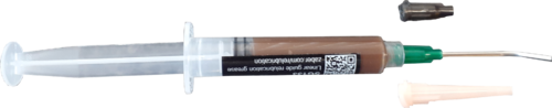
SG133 relubrication kit
-
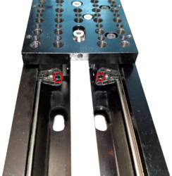
BLQ linear guide relubricating ports. Located on both ends of the carriage
-
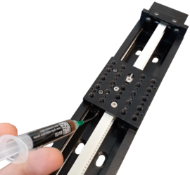
Re-lubricating BLQ linear guide
Noise Emissions
The A-weighted emission sound pressure level (SPL) of this device does not exceed 70 dB(A) during intended use.
Conventions used throughout this document
- Fixed width type indicates communication to and from a device. The ↵ symbol indicates a carriage return, which can be achieved by pressing enter when using a terminal program.
- An ASCII command followed by (T:xx) indicates a legacy T-Series Binary Protocol command that achieves the same result. For example,
- move abs 10000 (T:20:10000) shows that a move abs ASCII command can also be achieved with Binary command number 20.
- Not all ASCII commands have an equivalent Binary counterpart.
Device Overview
AutoDetect
Your BLQ-EC peripheral is equipped with AutoDetect, a feature that allows a Zaber controller to automatically configure its settings for the peripheral when it is connected.
 Important: The controller should always be powered down before disconnecting or connecting your BLQ-EC peripheral.
To connect the peripheral to a controller:
- Power off the controller.
- Connect the BLQ-EC peripheral.
- Power on the controller.
- The controller will activate the peripheral shortly after it is powered on.
See the Zaber controller user manual for more details on peripheral activation and control.
Connectors
Recommended controller(s) for your BLQ-EC peripheral are provided in the product specifications. Zaber's controllers and peripherals are designed for ease of use when used together. Optimal settings for each peripheral are automatically detected by Zaber's controllers when the device is connected.
For reference, the pinout for the peripheral cable connectors is shown below:
Pinout for D-sub 15 Connectors (peripherals)
| T3A Peripheral (male) | 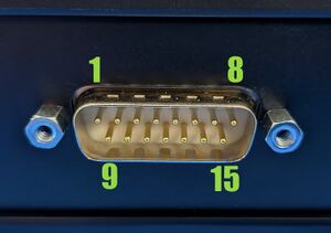
|
|---|---|
| T4A Peripheral (male) | 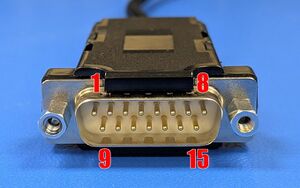
|
| Pin # | Function |
|---|---|
| 1 | +5V for Limits & Encoder |
| 2 | AutoDetect Data |
| 3 | N.C. |
| 4 | Away Sensor |
| 5 | Home Sensor |
| 6 | Ground |
| 7 | Motor B1 |
| 8 | Motor A1 |
| 9 | AutoDetect Clock |
| 10 | Encoder A |
| 11 | Encoder B |
| 12 | Encoder Index |
| 13 | Ground |
| 14 | Motor B2 |
| 15 | Motor A2 |
Not all pins are used for all models
Alternate Controllers
The BLQ-EC can be controlled by any 2-phase stepper motor controller with limit sensor and appropriate encoder input. We do not recommend using your own controller unless you are familiar with how to control a stepper motor with encoders and hall sensor limit switches. Damage to the device due to incorrect wiring is not covered by warranty.
Motors & Encoders
For motor and encoder information see the BLQ-EC product page
Limit Sensors
Hall effect sensors are used in the BLQ-EC as home sensors. The Hall sensors used are part number A1120LLHLT-T made by Allegro. Click here for data sheet. Your controller should be configured so the axis stops almost immediately (quick deceleration) when the sensors are triggered.
- PCB wire colour code:
- 5 Vdc input - red
- Home signal - yellow
- Away signal - white
- Ground - black
The Hall sensor has an open-collector output. The default output is high impedance when the Hall sensor is not active. When the sensor detects a magnet, the Hall sensor pulls the output low to ground.
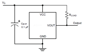
If you are not using a Zaber controller, ensure that your controller has a pull-up resistor on the output line of each Hall sensor as shown in the diagram. The bypass capacitor is optional, but may help to eliminate false triggering in noisy environments. The typical value for the pull-up resistor (RLOAD) is 10 kΩ and for the bypass capacitor is 0.1 uF to 1 uF. The larger the capacitance, the better the noise filtering but the slower the response time.
Installation
Physical Installation
Mounting
There are several options available for mounting Zaber stages. Use the mounting holes in the bottom to mount to a surface or to another stage. You might have to move the carriage to access the bottom mounting holes. Some stages have mounting holes in the end plates for mounting vertically. Mounting screws are included with most stages.
Caution: Some stages have threaded through-holes in the top mounting plate of the carriage. Be sure not to install mounting screws too deep, causing them to interfere with inside parts of the stage.
 Tip: To obtain the best pitch, roll, yaw and straightness performance, mount the stage to a known flat, stiff surface. Our tests were performed on a granite table, grade A flatness.
Tipping Hazard! Ensure stage is fastened to a secure surface before mounting load on carriage. An unmounted stage with a load presents a tipping hazard. Ensure loads are mounted securely to the carriage of the stage.
Trajectory Control and Behaviour
This section describes the behaviour of the axis trajectory when a movement command is issued.
Software Position Limits
The travel range of the axis is limited by the Minimum Position and Maximum Position settings. The factory settings for the axis are configured to match the physical travel range. If a customized range is desired, it can be changed by configuring the limit.min (T:106) and limit.max (T:44) settings to appropriate values. For the Current Position, query pos (T:60).
- Minimum Position
- When the Current Position is less than the Minimum Position value, the axis cannot move in the negative direction(towards the motor).
- Maximum Position
- When the Current Position is greater than the Maximum Position value, the axis cannot move in the positive direction(away from the motor).
Movement Speed
The movement speed of the axis depends on axis status and various speed settings. If the axis has not been initialized by the home (T:1) command or by moving towards the home end of the axis, movement speed will be constrained to fail-safe values. The home status of the axis can be determined by reading the limit.home.triggered(T:53:103) setting.
Movement speed of the axis is specified below:
- move vel (T:22)
- The axis will move at the specified speed regardless of home status.
- Knob movement in Velocity Mode
- The axis will move at the specified speed regardless of home status.
- The speed is specified by the knob.speedprofile (T:112) and knob.maxspeed (T:111) settings.
- Other movement commands - when the axis has not been homed
- The axis will move at the slower of the maxspeed (T:42) and limit.approach.maxspeed (T:41) settings.
- Other movement commands - when the axis has been homed
- The axis will move at the speed specified by the maxspeed (T:42) setting.
Warranty and Repair
For Zaber's policies on warranty and repair, please refer to the Ordering Policies.
Standard products
Standard products are any part numbers that do not contain the suffix ENG followed by a 4 digit number. Most, but not all, standard products are listed for sale on our website. All standard Zaber products are backed by a one-month satisfaction guarantee. If you are not satisfied with your purchase, we will refund your payment minus any shipping charges. Goods must be in brand new saleable condition with no marks. Zaber products are guaranteed for one year. During this period Zaber will repair any products with faults due to manufacturing defects, free of charge.
Custom products
Custom products are any part numbers containing the suffix ENG followed by a 4 digit number. Each of these products has been designed for a custom application for a particular customer. Custom products are guaranteed for one year, unless explicitly stated otherwise. During this period Zaber will repair any products with faults due to manufacturing defects, free of charge.
How to return products
Customers with devices in need of return or repair should contact Zaber to obtain an RMA form which must be filled out and sent back to us to receive an RMA number. The RMA form contains instructions for packing and returning the device. The specified RMA number must be included on the shipment to ensure timely processing.
Email Updates
If you would like to receive our periodic email newsletter including product updates and promotions.
Contact Information
Contact Zaber Technologies Inc by any of the following methods:
| Phone | 1-604-569-3780 (direct) 1-888-276-8033 (toll free in North America) |
|---|---|
| Fax | 1-604-648-8033 |
| #2 - 605 West Kent Ave. N., Vancouver, British Columbia, Canada, V6P 6T7 | |
| Web | www.zaber.com |
| Please visit our website for up to date email contact information. |
The original instructions for this product are available at https://www.zaber.com/manuals/BLQ-EC.
Appendix A: Default Settings
Please see the Zaber Support Page for default settings for this device.
Appendix B - Tensioning The Timing Belt
Although BLQ stages ship with the timing belt properly tensioned, it may at some point become necessary to re-tension it, although this is a rare occurrence. Maintaining the belt at its proper tension will ensure you are getting the best performance out of the stage. A clip-on instrument tuner that, when used as described below, is very effective at setting the belt to a precise tension. Please contact Zaber Technical Support.
To tension the timing belt:
- 1. Plug stage into PC and move to absolute position of 68960 microsteps. If the stage is shorter than 295 mm travel, move the carriage to a position of 34270 microsteps and tune to B (123.5 Hz) instead of C (65.4 Hz) (as described below). For a BLQ0070, move the carriage into contact with the home position bumpers and tune the other side of the belt to G# (207 Hz). The tuning procedure works better if the stage is not bolted down to anything.
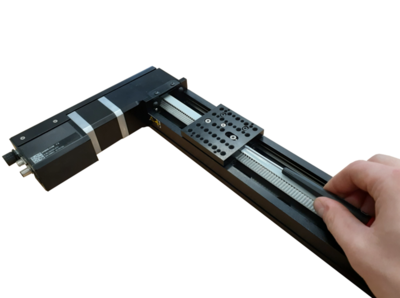
- 2. Attach instrument tuner to motor pulley housing as shown below. Tuner must not be touching the belt.
Position stage to absolute position of 68960 and attach tuner as shown.
- 3. Make sure the tuner is set to vibration ("VIB") mode. Turn on by pressing the large grey button on the front.
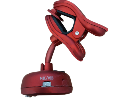
Make sure tuner is set to vibration mode.
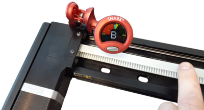
- 4. Pluck the belt in between the motor pulley housing and the carriage. The tuner should register a note. When the belt is properly tensioned, this note should be C2 (65.4 Hz).
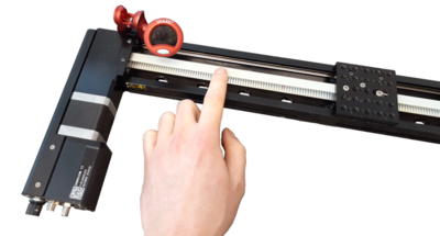
Pluck belt to measure tension.
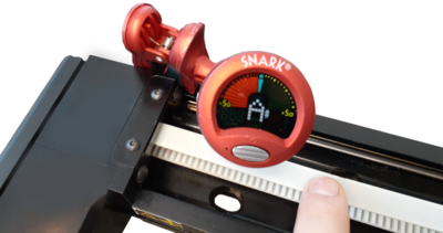
Read the note picked up by the tuner.
- 5. To make adjustments to the belt tension, loosen the M4 screw with a 2.5mm hex key about 1/4 turn from tight. The screw and the belt clamp under the stage top need to be able to slide along the slot. To increase the belt tension, use a 1.5mm hex key and turn the set screw clockwise- pushing the belt clamp towards the middle of the stage top. To decrease belt tension, turn the set screw counter-clockwise.
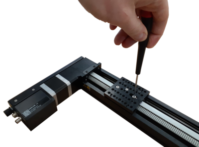
Loosen M4 screw then adjust setscrew to tighten or loosen belt.
- 6. Try to set the belt tension to about a B2 note. The tension will increase by about a semitone (e.g. B to C or C to C#) when the M4 screw is tightened. The final tension should be within 25 cents of C2 (1 semitone = 100 cents).
The final tension should be close to C2
- 7. The tuner may not initially register a note if the belt is too loose. As a rough guideline, you can hear what a C2 sounds like at www.tunemybass.com (select 4 string base with drop C tuning, then mouse over the lowest string to hear tone). It is a good idea to get a rough idea of what the tensioned belt will sound like so that you don't try to tune it to a C3 note - an octave higher than C2. This will be much too tight and could damage the belt or tensioning mechanism.
- 8. If the belt is close to the right tension, but the tuner still does not register a note, try attaching a metal plate or bracket to the stage top and clamp the tuner to that. This mounting should pick up the belt vibrations more easily.
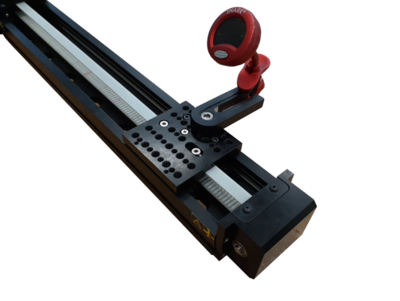
If the tuner is having difficulty picking up the belt vibration, try indirectly attaching it to the stage top as shown.
Specifications
Comparison
| Part Number | Travel Range | Accuracy (unidirectional) | Maximum Speed | Straightness of Travel |
|---|---|---|---|---|
| BLQ0070-E01CT3A | 70 mm (2.756") | 200 µm (0.007874") | 1100 mm/s (43.307"/s) | < 20 µm (< 0.000787") |
| BLQ0145-E01CT3A | 145 mm (5.709") | 200 µm (0.007874") | 1600 mm/s (62.992"/s) | < 30 µm (< 0.001181") |
| BLQ0295-E01CT3A | 295 mm (11.614") | 300 µm (0.011811") | 2000 mm/s (78.74"/s) | < 35 µm (< 0.001378") |
| BLQ0445-E01CT3A | 445 mm (17.52") | 400 µm (0.015748") | 2000 mm/s (78.74"/s) | < 40 µm (< 0.001575") |
| BLQ0595-E01CT3A | 595 mm (23.425") | 500 µm (0.019685") | 2000 mm/s (78.74"/s) | < 60 µm (< 0.002362") |
| Part Number | Weight | |||
|---|---|---|---|---|
| BLQ0070-E01CT3A | 1.7 kg (3.748 lb) | |||
| BLQ0145-E01CT3A | 1.85 kg (4.079 lb) | |||
| BLQ0295-E01CT3A | 2.15 kg (4.74 lb) | |||
| BLQ0445-E01CT3A | 2.5 kg (5.512 lb) | |||
| BLQ0595-E01CT3A | 2.75 kg (6.063 lb) |
Charts and Notes
Product Change Notices
Click here to view the current product change notices and subscribe to future change notifications.