Manuals/X-ASR
Disclaimer
Zaber’s products are not intended for use in any critical medical, aviation, or military applications or situations where a product's use or failure could cause personal injury, death, or damage to property. Zaber disclaims any warranty of fitness for a particular purpose. The user of this product agrees to Zaber's general terms and conditions of sale.
Precautions
Zaber’s motion control devices are precision instruments and must be handled with care. In particular, moving parts must be treated with care. Avoid axial loads in excess of the rated thrust load, axial and radial impact, dust and other contaminants and damage to the drive components. These will reduce the performance of the device below stated specifications.
Noise Emissions
The A-weighted emission sound pressure level (SPL) of this device does not exceed 70 dB(A) during intended use.
The A-weighted emission sound pressure level (SPL) of this device may reach up to 79 dB(A) if the stage is stalled.
Conventions used throughout this document
- Fixed width type indicates communication to and from a device. The ↵ symbol indicates a carriage return, which can be achieved by pressing enter when using a terminal program.
Quick Tutorial
We recommend using Zaber Launcher to communicate with the device(s). For other software options, see the Software page. Please refer to the Protocol Manual for more detailed information on the available commands.
Initial Set-up
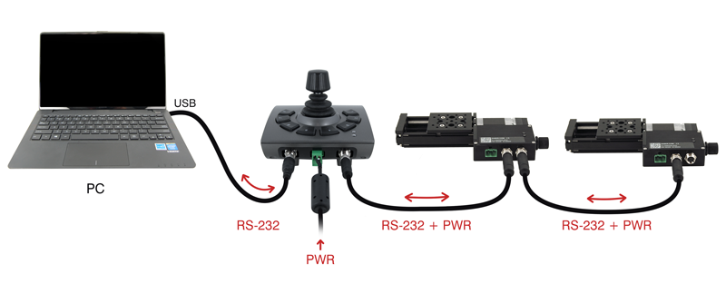
- Daisy chain all integrated devices and controllers together using the RS-232 "Prev" and "Next" connectors (see Daisy-Chaining Devices for more details).
- Next, supply power to one or more devices. Many products share power through the daisy-chain cables. The green power indicator on each should light up.
- Turn the knob to move a positioner. Most positioners will only move in one direction until they reach a home sensor at one limit of travel. Then they will move in both directions over full travel.
- Download and install Zaber Launcher. Start Zaber Launcher.
- Create a New Connection and select the communications port the first controller is connected to. For instructions on how to find the available communication ports on your system, please refer to: Appendix A - Available Communications Ports.
- If multiple devices are detected and there are conflicting device numbers, Zaber Launcher will renumber them or you can renumber them as desired. The first device in the chain (closest to the computer) will become Device 1, the next will become Device 2, and so on.
Initialization
Every time the device is powered up or reset, you should return the positioner to the home position. This is achieved by sending the home command to the individual device or all devices. Until this is done, most positioners will only allow motion in one direction, towards the sensor.
If it is not possible in your application to home the positioner after every power-up, see the tools parking command. Parking allows the device to be turned off and then used at a later time without first having to home the axes.
Using the Device
Several commonly used ASCII commands are shown below. For a full list of available commands, please refer to the Protocol Manual.
| Command | Description |
|---|---|
| /1 1 get pos↵ | Query the current position of Device #1 Axis #1. |
| /1 1 move abs 10000↵ | Move Device #1, Axis #1 to position 10000 microsteps. |
| /2 1 move rel -12800↵ | Move Device #2, Axis #1 in the negative direction by 12800 microsteps. |
| /1 stop↵ | Decelerate and stop ALL axes on Device 1. An axis number of 0 or no axis number implies all axes on the device, or the device itself. |
| /move vel 153600↵ | Move ALL devices and ALL axes in the positive direction at the speed 153600. A device address of 0 or no device address implies all devices in the chain. |
Modifying Device Settings
Here are some examples if you would like to customize particular device or axis settings. Refer to the Protocol Manual for detailed descriptions of each setting.
| Command | Description |
|---|---|
| /1 set maxspeed 100000↵ | Set the speed of all axes on the device. |
| /1 get maxspeed↵ | Query the maximum speed of all axes on the device. |
| /1 system restore↵ | Restore all the settings of Device 1 to the default. |
Firmware Upgrades
To allow access to new features and bug fixes, this Zaber device can be upgraded remotely through the Firmware Upgrade app in Zaber Launcher. In the "My Connections" window, click on the “...” menu to the right of the device and select “Firmware Upgrade”.
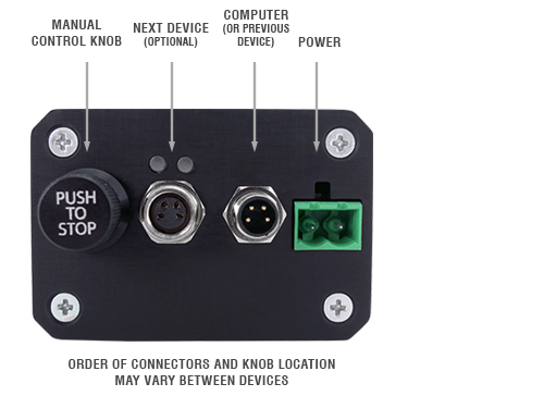
Device Overview
Connectors
All images are shown looking into the device.
Power
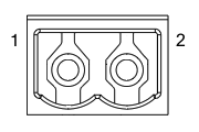
|
Pin | Description |
|---|---|---|
| 1 | 24 - 48 V | |
| 2 | Device GND |
Note: This product requires a CE/UL approved AC/DC power converter such as Zaber's PS13S, PS14S or PS15S with a DC cord of at most 3 m.
Note: As of February 2022, the power supplies Zaber provides are isolated and thus the device is not connected to Earth ground. Prior to 2022, most power supplies were non-isolated. Isolated units can be distinguished by the "S" suffix in their Zaber part number (eg. PS14S), which is marked on the label on the bottom of the power supply.
RS-232 Communications
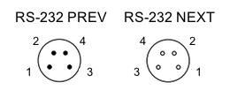
|
Pin | Previous | Next |
|---|---|---|---|
| 1 | Power (max 4 A) | Power (max 4 A) | |
| 2 | Ground | Ground | |
| 3 | Receive | Transmit | |
| 4 | Transmit | Receive |
- Default Settings
- Baud rate: 115200
- Protocol: Zaber ASCII
- Specifications
- Supported Protocols: Zaber ASCII
- Supported baud rates: 9600, 19200, 38400, 57600, 115200
- Bits: 8
- Parity: None
- Stop Bits: 1
- Flow Control: None
D12 IO pinout
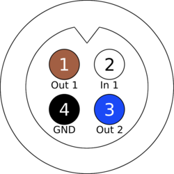
|
Pin | Description |
|---|---|---|
| 1 | Output #1 | |
| 2 | Input #1 | |
| 3 | Output #2 | |
| 4 | Ground |
Note: See I/O Usage and Examples for additional information.
Note: Any cables connected to the I/O port should be limited to 3 m in length.
Other Connectors
For any connections not described in this document, cables should be limited to a length of 3 m.
Indicators
- Green (Device) - Power
- On: Controller is operational.
- Blinking twice per second: The power supply voltage or controller temperature is out of range.
- Red (Device) - System Error
- On/blinking: An error has occurred. Please contact Zaber Technical Support.
- Yellow (Device) - Communication
- On: Data is being transferred.
- Blinking twice per second: Packet corruption has occurred for ASCII commands sent with a checksum.
- Yellow (Axis) - Axis Status
- On: Axis is moving.
- Blue (Axis) - Warning/Error
- Blinking twice per second: Driver is disabled due to over-temperature, out-of-range voltage or other driver fault; or due to user request. See Fx Warning Flags. Note: This may occur for a few seconds on power-up as device initializes.
- Fading in and out slowly: The axis is parked. See the tools parking command.
Installation
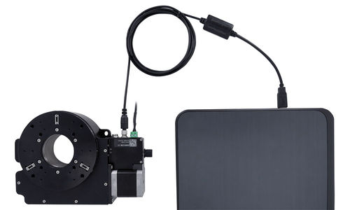
The X-ASR can be connected to a computer as follows:
- Plug the M8 to USB adaptor (X-USBDC) into one of your computer's USB ports, then attach the device to the adaptor. You may need to use a cable extension to reach your computer. There is no need to power down or reboot the computer.
- Connect the power plug of your power supply to the power connector of the device. The green LED should light up indicating the device has power.
- Additional devices can simply be daisy-chained to the first. See Daisy-Chaining Devices below.
- Install software from the Software page. For the initial setup, using Zaber Launcher is recommended.
As a simple first test, try entering:
The parameter of 10000 in the move command above specifies 10000 microsteps. To see the microstep size (default resolution) for the positioner and how it translates to displacement, first go to the product overview page, find your product, click through to the product's webpage, and click on the "Series Specs" tab. The microstep size (default resolution) will be shown in the list of product specs either in the "Group Specifications" section or the "Comparison" section.
Daisy-Chaining Devices
Multiple devices can be connected together in a chain through the Prev and Next connectors. This allows any number of devices to be controlled from a single connection to a computer, reducing cabling demands. In addition, X-Series devices carry power through the daisy chain, so in most cases a power supply only needs to be connected to one device in the chain. Whenever a device is added or removed from a chain, a renumber command should be sent to prevent device address conflicts. If there are device address conflicts, Zaber Launcher will renumber automatically the next time you use it to connect to the chain.
Note: Daisy-chaining devices with cable lengths exceeding 8 m (25 ft) is not recommended.
Shipping Plate Removal
The (X-)ASR205B205B and (X-)ASR305B305B stages are fitted with sheet metal plates to prevent shock loads from the stage during shipping. Follow the instructions below to remove the shipping plates.
| Instructions | (X-)ASR305B305B, (X-)ASR205B205B |
|---|---|
| 1. Connect the stage to a controller. | 
|
| 2. Remove the 8 M3 screws securing the shipping plates to the base and mid-plates as shown. | 
|
| 3. With these screws removed, use the controller to move the upper-axis in order to gain access to the screws on the underside of the top-plate as shown. | 
|
| 4. Remove the two screws holding the upper-axis shipping plate to the underside of the top plate. Move the upper-axis in the opposite direction in order to access and remove the two screws under the opposite side of the top-plate. Slide the upper-axis shipping plate out and set it aside. | 
|
| 5. Repeat the same procedure for the lower-axis shipping plate. Move the lower-axis to gain access to the 4 screws holding the lower-axis shipping plate to the underside of the mid-plate. When all 4 screws are removed, remove the plate. The stage is now ready to be installed and used. | 
|
Mounting
The (X-)ASR050B050B and (X-)ASR100B120B stages are mounted using adaptor plates. The (X-)ASR205B205B and (X-)ASR305B305B mount directly to compatible microscopes and use adaptor plates only for breadboard mounting. The following adaptor plates are currently available:
| (X-)ASR100B120B | (X-)ASR050B050B | (X-)ASR205B205B / (X-)ASR305B305B |
|---|---|---|
| AP110 - for mounting to standard M6 or 1/4"-20 breadboards. | AP137 - for mounting to standard M6 or 1/4"-20 breadboards. | AP160 - for mounting to standard M6 or 1/4"-20 breadboards. |
| AP111 - for mounting to Leica, Zeiss and Olympus microscopes. | ||
| AP114 - for mounting to Nikon inverted microscopes. | ||
| AP125 - for mounting to Olympus BX upright microscopes. | ||
| AP131 - for mounting to Olympus IX inverted microscopes. |
For more details about these adaptor plates, please see our accessory page.
The adaptor plates are attached to the (X-)ASR using 2 or 3 M3 screws per plate. To install the adaptors, align them as shown in the pictures below and tighten the M3 screws. The stage will need to be plugged into the controller so that you are able to move the lower axis and gain access to the screw holes.
| Instructions | (X-)ASR100B120B |
|---|---|
| 1. Position the lower axis such that you have access to the adaptor plate mounting screw holes. | 
|
| 2. Place an adaptor plate underneath the (X-)ASR base. | 
|
| 3. Install and tighten the M3 screws. | 
|
The (X-)ASR205B205B and (X-)ASR305B305B stages mount directly to the following microscopes:
- Olympus MX61
- Nikon L200N
- Nikon L300N
Custom adaptor plates are available upon request. Please contact Zaber technical support at 1-888-276-8033 or contact@zaber.com for more information.
Operation
Most of the information you will need to operate the stage using the X-MCC controller can be found in the X-MCC User Manual. The sections below provide some additional information that is specific to the (X-)ASR stages.
(X-)ASR Inserts
The different (X-)ASR stages accept the following size inserts:
| Stage | Insert size |
|---|---|
| (X-)ASR050B050B | 82 x 82 mm |
| (X-)ASR100B120B | 160 x 110 mm |
| (X-)ASR205B205B | 219 x 219 mm |
| (X-)ASR305B305B | 300 x 300 mm |
The following inserts are currently available:
| (X-)ASR050B050B | (X-)ASR100B120B | (X-)ASR205B205B | (X-)ASR305B305B |
|---|---|---|---|
| AM141 - for holding 30-60mm petri dishes | AM108 - for holding various petri dishes or microscope slides | AM154 - M6 x 50 mm breadboard | AM155 - M6 x 50 mm breadboard |
| AM142 - for holding 1" x 3" microscope slides | AM109 - Microplate holder (single plate) | AM223 - Microplate holder (2 plates) | AM224 - Microplate holder (6 plates) |
| AM143 - M6 x 25 mm breadboard | AM126 - M6 x 25 mm breadboard |
For more details about these inserts, please see our accessory page.
Installation and Removal - (X-)ASR050B050B and (X-)ASR100B120B
On the (X-)ASR050B050B and (X-)ASR100B120B, the inserts are held in place by a spring clip in one corner of the aperture. To install an insert, place the one corner up against the spring first. While holding this corner down, push the insert towards the spring clip and snap the opposing corner into place. Removal is the reverse of this procedure.
For most applications, the spring clip should provide sufficient force to hold the insert in place, while still allowing quick changes between inserts. For applications requiring more secure mounting, custom inserts can be provided that can be secured to the (X-)ASR using 4 M2 screws.
| Instructions | (X-)ASR100B120B |
|---|---|
| 1. To install an insert, first position the corner next to the spring clip as shown. | 
|
| 2. While holding down the corner next to the spring clip, push the opposite corner down. | 
|
Installation and Removal - (X-)ASR205B205B and (X-)ASR305B305B
On the (X-)ASR205B205B and (X-)ASR305B305B, the inserts are held in place by 3 M4 flat head screws. The screws mate with 3 matching chamfers on the insert to kinematically constrain it. Some inserts also allow for mounting using 16 or 24 M3 screws around the perimeter of the insert. The perimeter screws will secure the insert against high loads, but may compromise the flatness of the stage. It is only recommended that these screws be used when the necessary to prevent the insert from shifting under high loads.
| Instructions | (X-)ASR305B305B |
|---|---|
| 1. To install an insert, first line up the 3 insert chamfers with the 3 screw pockets in the (X-)ASR top plate. | 
|
| 2. Screw the 3 M4 x 8 flat head screws into the holes in the top plate as shown. Tighten the screws evenly until the insert is held securely. | 
|
| 3. If required, the insert can be leveled using the 3 M4 set screws adjacent to the flat head screws. Before adjusting the set screws, loosen the flat head screws. | 
|
Setting Home and Away Sensors
The X-ASR provides adjustable travel limits for each axis. A home sensor sets the 0 position of each axis and an away sensor determines the maximum travel range.
Limit adjustment is performed by moving the magnets which trigger the sensor. The limit switch magnets are attached to the bottoms of the limit adjustment screws shown in the pictures below.
![]() Important: If adjusting the magnets outwards, make adjustments in small increments. Exceeding the nominal factory set travel range by more than 3 mm can cause the device to become stuck at one end of travel.
Important: If adjusting the magnets outwards, make adjustments in small increments. Exceeding the nominal factory set travel range by more than 3 mm can cause the device to become stuck at one end of travel.
| (X-)ASR100B120B | |
|---|---|
| Upper axis limit switch magnets | 
|
| Lower axis limit switch magnets | 
|
To adjust the limits, loosen the screws by about 1/2 turn, slide the screw to the desired location and re-tighten. Make sure that the green hall sensor PCB (visible through the magnet adjustment slots) always stays in between the limit screws.
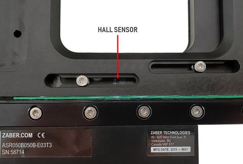
When adjusting the limit switch magnets, ensure that the green sensor PCB remains in between two magnets.

Software
In addition to the regular software options available for all Zaber devices, the X-ASR is supported by Micro-Manager open source microscopy software. Micro-manager can be downloaded for free from the Micro-Manager website.
Trajectory Control and Behaviour
This section describes the behaviour of the axis trajectory when a movement command is issued.
Software Position Limits
The travel range of the axis is limited by the Minimum Position and Maximum Position settings. The factory settings for the axis are configured to match the physical travel range. If a customized range is desired, it can be changed by configuring the limit.min and limit.max settings to appropriate values. For the Current Position, query pos.
- Minimum Position
- When the Current Position is less than the Minimum Position value, the axis cannot move in the negative direction(towards the motor).
- Maximum Position
- When the Current Position is greater than the Maximum Position value, the axis cannot move in the positive direction(away from the motor).
Movement Speed
The movement speed of the axis depends on axis status and various speed settings. If the axis has not been initialized by the home command or by moving towards the home end of the axis, movement speed will be constrained to fail-safe values. The home status of the axis can be determined by reading the limit.home.triggered setting.
Movement speed of the axis is specified below:
- move vel
- The axis will move at the specified speed regardless of home status.
- Other movement commands - when the axis has not been homed
- The axis will move at the slower of the maxspeed and limit.approach.maxspeed settings.
- Other movement commands - when the axis has been homed
- The axis will move at the speed specified by the maxspeed setting.
I/O Usage and Examples
The X-ASR features one digital input and two digital outputs that operate on a +5 V supply and are TTL compatible. The input and output capabilities of the X-ASR can also be used with triggers to perform actions based on the current value of the I/O channel.
Digital Inputs
The input will draw up to 1 mA during operation.

Reading the input is accomplished by sending the unit an io get di command, as shown below.
/1 io get di 1↵
@01 0 OK IDLE -- 0
This command queries the input on the device, in this case input 1, which is low.
Digital Outputs
The digital outputs use an open collector buffer with a pre-installed 1 kΩ pull up resistor to +5 V. Each output can sink up to 20 mA.

The digital outputs are set through the io set do command, as shown below.
/1 io set do 2 1↵
@01 0 OK IDLE –- 0
/1 io set do 1 0↵
@01 0 OK IDLE –- 0
The first command sets the second digital output high (5 V). The second command sets the first digital output low (0 V).
Current Controller Tuning
In firmware versions 7.27 and up, this product's current controller can be tuned to modify the performance of the stepper motor. The current controllers on Zaber products are already tuned to perform well in the vast majority of situations. You should only need to tune the current controller if the default tuning is not providing sufficient performance.
Use the Current Tuner application in Zaber Launcher to tune the performance of the motor.
Troubleshooting X-Series Motion Devices
The following sections contain tips for troubleshooting common problems.
Front Panel Indicators
- Green LED on.
- The device is powered on and is operating normally.
- Green LED flashes slowly.
- The operating conditions of the device are outside of the recommended range.
- This will occur when the supply voltage is either over or under the recommended range or the controller temperature has exceeded the set limit. Check the following:
- The input voltage is within the operational range of the device. This can be read from the device with the get system.voltage command.
- The device temperature is within range. This can be read from the device with the get system.temperature command.
- Green LED off.
- The device is not powered.
- Check the supply connections and power adaptor for correct operation.
- Red LED on or flashing.
- A critical error has occurred.
- Please contact Zaber Technical Support.
- Yellow LED always off or flashes but no reply.
- There are communication errors.
- Please see the Communication Errors section below.
- Blue (or Green for Firmware versions <7.15) LED Fades In and Out.
- The axis is parked.
- Issue a tools parking unpark command, or home the axis.
- Blue LED blinking twice per second. Axis does not move.
- Driver may be disabled due to over-temperature, out-of-range voltage or other driver fault; or due to user request.
- See Fx Warning Flags.
- Once the issue has been resolved, send driver enable.
Unexpected Behaviour
- The axis doesn't respond to a move command.
- The axis may need to be homed before use.
- Send the home command.
- The axis is moving on its own and running against the ends of travel.
- The position encoder has de-synchronized.
- Reset the device by power cycling it or sending the system reset command, then re-initialize it with the home command.
- The axis is moving very slowly. It used to move faster.
- The speed settings may have been changed inadvertently.
- Send a system restore command.
- The axis makes louder than normal noise during travel and is frequently slipping.
- This condition happens if the thrust needed is more than the thrust available from the axis.
- Check the following:
- The force on the axis is less than the maximum thrust.
- The voltage matches the specified voltage. Read the voltage using the get system.voltage command. Voltage less than the specified voltage for the device will reduce the positioner’s maximum thrust.
- Test the following:
- Try a slower target velocity. Stepper motors produce more thrust when moving slowly.
- Try a lower acceleration and deceleration.
- Clean the screw and lightly re-grease it with a grease that does not degrade plastics.
- The axis has repeatability errors smaller than 4 full steps.
- If steps aren't being skipped, friction or loose parts may still cause some variation when returning to a position.
- Please contact Zaber Technical Support.
- The axis doesn't cover the full range of travel, or runs into the end.
- A setting might have been inadvertently changed.
- home the axis to see if this corrects the behaviour.
- Send a system restore command.
- The positioner's motor unexpectedly shuts off. An Fx warning flag is present.
- The motor over-temperature protection switch has been tripped. This sensor will trip if the positioner's maximum continuous thrust specification is exceeded for too long. To prevent this condition from occurring again, reduce the average force that the motor outputs by reducing acceleration, reducing the load, or lowering the duty cycle.
- Send a driver enable command. The axis does not require homing.
Communication Errors
- There is no communication with the device; the Yellow LED does not come on or flash.
- There are several things that should be checked:
- Make sure the correct serial port is selected. Try selecting other serial ports in the software.
- Check the baud rate, hand shaking, parity, stop bit, etc. when configuring the serial communications software. The required settings are listed in the RS-232 Communications section above.
- Make sure there are no bent pins in the ends of all the data cables
- Make sure the device is powered. The Green LED should be on.
- If the computer is a laptop running on batteries, try plugging in the power. Some laptops disable the serial ports when running on batteries.
- Make sure a null modem adaptor or cable is not being used.
- Make sure the correct adaptors (if any) are being used. Refer to the pinouts in the RS-232 Communications section above.
- If the problem was encountered when trying to control the device with custom software, try using Zaber Launcher or Zaber Console (available from the Zaber website) to verify that the hardware is functioning properly.
- Two or more devices both respond to commands sent to device 1.
- Most devices are shipped with their device number set as 1. If you connect to the devices with Zaber Launcher, it will automatically renumber them if needed. If you aren't able to install and open Zaber Launcher, send the renumber command in the software you are using to set all of the device numbers to different values.
- The Yellow LED comes on briefly when sending a command, but the axis does not move and does not reply.
- Check baud rate, hand shaking, parity, stop bit, etc. are set as per the RS-232 Communications defaults.
- The device numbers may not be what is expected, issue a renumber command. Make sure that the computer does not transmit anything else while the devices renumber.
Slipping and Stalling
- The axis makes noise but does not move.
- The axis is stalling.
- Try removing all external loads. If the axis now extends and retracts normally, the problem is excessive load. Try to reduce the load and ensure the load is less than the maximum thrust. A higher thrust or torque can be achieved by lowering the speed of the axis using the maxspeed setting.
- If an axis is stalling with no external load at default speed and acceleration settings then it requires servicing.
Warranty and Repair
For Zaber's policies on warranty and repair, please refer to the Ordering Policies.
Standard products
Standard products are any part numbers that do not contain the suffix ENG followed by a 4 digit number. Most, but not all, standard products are listed for sale on our website. All standard Zaber products are backed by a one-month satisfaction guarantee. If you are not satisfied with your purchase, we will refund your payment minus any shipping charges. Goods must be in brand new saleable condition with no marks. Zaber products are guaranteed for one year. During this period Zaber will repair any products with faults due to manufacturing defects, free of charge.
Custom products
Custom products are any part numbers containing the suffix ENG followed by a 4 digit number. Each of these products has been designed for a custom application for a particular customer. Custom products are guaranteed for one year, unless explicitly stated otherwise. During this period Zaber will repair any products with faults due to manufacturing defects, free of charge.
How to return products
Customers with devices in need of return or repair should contact Zaber to obtain an RMA form which must be filled out and sent back to us to receive an RMA number. The RMA form contains instructions for packing and returning the device. The specified RMA number must be included on the shipment to ensure timely processing.
Email Updates
If you would like to receive our periodic email newsletter including product updates and promotions.
Contact Information
Contact Zaber Technologies Inc by any of the following methods:
| Phone | 1-604-569-3780 (direct) 1-888-276-8033 (toll free in North America) |
|---|---|
| Fax | 1-604-648-8033 |
| #2 - 605 West Kent Ave. N., Vancouver, British Columbia, Canada, V6P 6T7 | |
| Web | www.zaber.com |
| Please visit our website for up to date email contact information. |
The original instructions for this product are available at https://www.zaber.com/manuals/X-ASR.
Appendix A - Available Communications Ports
The following instructions outline how to find installed serial ports on your computer.
Windows
- Open Search or Run from the Start Menu or Taskbar, type "Device Manager" and press enter.
- Expand the Ports (COM & LPT) category.
- In this example there are two serial ports available (COM1 and COM15), which are both USB adaptors.


Linux
- Finding devices
- Open a terminal and execute the following command:
- dmesg | grep -E ttyU\?S↵
- The response will be similar to the following:
[ 2.029214] serial8250: ttyS0 at I/O 0x3f8 (irq = 4) is a 16550A
[ 2.432572] 00:07: ttyS0 at I/O 0x3f8 (irq = 4) is a 16550A
[ 2.468149] 0000:00:03.3: ttyS4 at I/O 0xec98 (irq = 17) is a 16550A
[ 13.514432] usb 7-2: FTDI USB Serial Device converter now attached to ttyUSB0 - This shows that there are 3 serial ports available: ttyS0, ttyS4 and ttyUSB0 (a USB adaptor)
- Checking port permissions
- Using the ports found above, execute the following command
- ls -l /dev/tty{S0, S4, USB0}↵
- The permissions, given below, show that a user has to be root or a member of the dialout group to be able to access these devices
crw-rw---- 1 root dialout 4, 64 Oct 31 06:44 /dev/ttyS0
crw-rw---- 1 root dialout 4, 68 Oct 31 06:45 /dev/ttyS4
crw-rw---- 1 root dialout 188, 0 Oct 31 07:58 /dev/ttyUSB0
- Checking group membership
- groups↵
- The output will be similar to the following:
adm cdrom sudo dip plugdev users lpadmin sambashare
Notice that dialout is not in the list - A user can be added to the dialout group with the following command
- sudo adduser $USER dialout↵
- Group membership will not take effect until the next logon.
OSX
- Finding devices
- Open a terminal and execute the following command:
- ls /dev/cu.*serial*
- The response will be similar to the following:
/dev/cu.usbserial-FTB3QAET
/dev/cu.usbserial-FTEJJ1YW - This shows that there are two serial ports available, both of which happen to be USB adaptors.
- There may be other devices that match this query, such as keyboards or some web cameras. To determine which one corresponds to your USB serial cable, try repeating the command with and without the cable connected to the computer, to see which one appears and disappears.