Manuals/ASR
Disclaimer
Zaber’s products are not intended for use in any critical medical, aviation, or military applications or situations where a product's use or failure could cause personal injury, death, or damage to property. Zaber disclaims any warranty of fitness for a particular purpose. The user of this product agrees to Zaber's general terms and conditions of sale.
Precautions
Zaber's autodetect peripheral axes are designed to be used effortlessly with Zaber's line of autodetect controllers. The ASR includes onboard memory that allows Zaber's controllers to autodetect the model and set reasonable parameters. See the Protocol Manual for more information on how to modify the settings. Damage to the axis may result if the settings are not correct. To use your Zaber peripheral with a third-party controller, review the motor, sensor, and encoder specifications and pin-outs carefully.
Zaber’s motion control devices are precision instruments and must be handled with care. In particular, moving parts must be treated with care. Avoid axial loads in excess of the rated thrust load, axial and radial impact, dust and other contaminants and damage to the lead screw thread. These will reduce the performance of the device below stated specifications.
Noise Emissions
The A-weighted emission sound pressure level (SPL) of this device does not exceed 70 dB(A) during intended use.
The A-weighted emission sound pressure level (SPL) of this device may reach up to 79 dB(A) if the stage is stalled.
Conventions used throughout this document
- Fixed width type indicates communication to and from a device. The ↵ symbol indicates a carriage return, which can be achieved by pressing enter when using a terminal program.
- An ASCII command followed by (T:xx) indicates a legacy T-Series Binary Protocol command that achieves the same result. For example,
- move abs 10000 (T:20:10000) shows that a move abs ASCII command can also be achieved with Binary command number 20.
- Not all ASCII commands have an equivalent Binary counterpart.
Device Overview
AutoDetect
Your ASR peripheral is equipped with AutoDetect, a feature that allows a Zaber controller to automatically configure its settings for the peripheral when it is connected.
![]() Important: The controller should always be powered down before disconnecting or connecting your ASR peripheral.
Important: The controller should always be powered down before disconnecting or connecting your ASR peripheral.
To connect the peripheral to a controller:
- Power off the controller.
- Connect the ASR peripheral.
- Power on the controller.
- The controller will activate the peripheral shortly after it is powered on.
See the Zaber controller user manual for more details on peripheral activation and control.
Connectors
Recommended controller(s) for your ASR peripheral are provided in the product specifications. Zaber's controllers and peripherals are designed for ease of use when used together. Optimal settings for each peripheral are automatically detected by Zaber's controllers when the device is connected.
For reference, the pinout for the peripheral cable connectors is shown below:
Pinout for D-sub 15 Connectors (peripherals)
| T3A Peripheral (male) | 
|
|---|---|
| T4A Peripheral (male) | 
|
| Pin # | Function |
|---|---|
| 1 | +5V for Limits & Encoder |
| 2 | AutoDetect Data |
| 3 | N.C. |
| 4 | Away Sensor |
| 5 | Home Sensor |
| 6 | Ground |
| 7 | Motor B1 |
| 8 | Motor A1 |
| 9 | AutoDetect Clock |
| 10 | Encoder A |
| 11 | Encoder B |
| 12 | Encoder Index |
| 13 | Ground |
| 14 | Motor B2 |
| 15 | Motor A2 |
Not all pins are used for all models
Alternate Controllers
The ASR can be controlled by any 2-phase stepper motor controller with limit sensor input. We do not recommend using your own controller unless you are familiar with how to control a stepper motor with hall sensor limit switches. Damage to the device due to incorrect wiring is not covered by warranty.
Motors
For motor information see the ASR product page
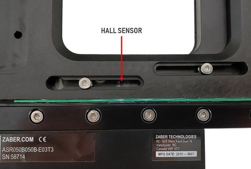
Limit Sensors
Hall effect sensors are used in the ASR as home and away sensors. The Hall sensors used are part number A1120LLHLT-T made by Allegro. Click here for data sheet. Your controller should be configured so the axis stops almost immediately (quick deceleration) when the sensors are triggered.
- PCB wire colour code:
- 5 Vdc input - red
- Home signal - yellow
- Away signal - white
- Ground - black
The Hall sensor has an open-collector output. The default output is high impedance when the Hall sensor is not active. When the sensor detects a magnet, the Hall sensor pulls the output low to ground.

If you are not using a Zaber controller, ensure that your controller has a pull-up resistor on the output line of each Hall sensor as shown in the diagram. The bypass capacitor is optional, but may help to eliminate false triggering in noisy environments. The typical value for the pull-up resistor (RLOAD) is 10 kΩ and for the bypass capacitor is 0.1 uF to 1 uF. The larger the capacitance, the better the noise filtering but the slower the response time.
Installation
Shipping Plate Removal
The (X-)ASR205B205B and (X-)ASR305B305B stages are fitted with sheet metal plates to prevent shock loads from the stage during shipping. Follow the instructions below to remove the shipping plates.
| Instructions | (X-)ASR305B305B, (X-)ASR205B205B |
|---|---|
| 1. Connect the stage to a controller. | 
|
| 2. Remove the 8 M3 screws securing the shipping plates to the base and mid-plates as shown. | 
|
| 3. With these screws removed, use the controller to move the upper-axis in order to gain access to the screws on the underside of the top-plate as shown. | 
|
| 4. Remove the two screws holding the upper-axis shipping plate to the underside of the top plate. Move the upper-axis in the opposite direction in order to access and remove the two screws under the opposite side of the top-plate. Slide the upper-axis shipping plate out and set it aside. | 
|
| 5. Repeat the same procedure for the lower-axis shipping plate. Move the lower-axis to gain access to the 4 screws holding the lower-axis shipping plate to the underside of the mid-plate. When all 4 screws are removed, remove the plate. The stage is now ready to be installed and used. | 
|
Mounting
![]() WARNING: Do not attempt to mount ASR stages to a flat surface without using adaptor plates. Damage to the stage will occur if mounting screws are tightened without proper support under the recessed mounting surfaces.
WARNING: Do not attempt to mount ASR stages to a flat surface without using adaptor plates. Damage to the stage will occur if mounting screws are tightened without proper support under the recessed mounting surfaces.
The (X-)ASR050B050B and (X-)ASR100B120B stages are mounted using adaptor plates. The (X-)ASR205B205B and (X-)ASR305B305B use adaptor plates for breadboard mounting but can be mounted directly to compatible microscopes.
The following adaptor plates are currently available:
| (X-)ASR100B120B | (X-)ASR050B050B | (X-)ASR205B205B / (X-)ASR305B305B |
|---|---|---|
| AP110 - for mounting to standard M6 or 1/4"-20 breadboards. | AP137 - for mounting to standard M6 or 1/4"-20 breadboards. | AP160 - for mounting to standard M6 or 1/4"-20 breadboards. |
| AP111 - for mounting to Leica, Zeiss and Olympus microscopes. | ||
| AP114 - for mounting to Nikon inverted microscopes. | ||
| AP125 - for mounting to Olympus BX upright microscopes. | ||
| AP131 - for mounting to Olympus IX inverted microscopes. |
For more details about these adaptor plates, please see our accessory page.
The adaptor plates are attached to the (X-)ASR using 2 or 3 M3 screws per plate. To install the adaptors, align them as shown in the pictures below and tighten the M3 screws. The stage will need to be plugged into the controller so that you are able to move the lower axis and gain access to the screw holes.
| Instructions | (X-)ASR100B120B |
|---|---|
| 1. Position the lower axis such that you have access to the adaptor plate mounting screw holes. | 
|
| 2. Place an adaptor plate underneath the (X-)ASR base. | 
|
| 3. Install and tighten the M3 screws. | 
|
The (X-)ASR205B205B and (X-)ASR305B305B stages mount directly to the following microscopes:
- Olympus MX61
- Nikon L200N
- Nikon L300N
Custom adaptor plates are available upon request. Please contact Zaber technical support at 1-888-276-8033 or contact@zaber.com for more information.
Operation
Most of the information you will need to operate the stage using the X-MCC controller can be found in the X-MCC User Manual. The sections below provide some additional information that is specific to the (X-)ASR stages.
(X-)ASR Inserts
The different (X-)ASR stages accept the following size inserts:
| Stage | Insert size |
|---|---|
| (X-)ASR050B050B | 82 x 82 mm |
| (X-)ASR100B120B | 160 x 110 mm |
| (X-)ASR205B205B | 219 x 219 mm |
| (X-)ASR305B305B | 300 x 300 mm |
The following inserts are currently available:
| (X-)ASR050B050B | (X-)ASR100B120B | (X-)ASR205B205B | (X-)ASR305B305B |
|---|---|---|---|
| AM141 - for holding 30-60mm petri dishes | AM108 - for holding various petri dishes or microscope slides | AM154 - M6 x 50 mm breadboard | AM155 - M6 x 50 mm breadboard |
| AM142 - for holding 1" x 3" microscope slides | AM109 - Microplate holder (single plate) | AM223 - Microplate holder (2 plates) | AM224 - Microplate holder (6 plates) |
| AM143 - M6 x 25 mm breadboard | AM126 - M6 x 25 mm breadboard |
For more details about these inserts, please see our accessory page.
Installation and Removal - (X-)ASR050B050B and (X-)ASR100B120B
On the (X-)ASR050B050B and (X-)ASR100B120B, the inserts are held in place by a spring clip in one corner of the aperture. To install an insert, place the one corner up against the spring first. While holding this corner down, push the insert towards the spring clip and snap the opposing corner into place. Removal is the reverse of this procedure.
For most applications, the spring clip should provide sufficient force to hold the insert in place, while still allowing quick changes between inserts. For applications requiring more secure mounting, custom inserts can be provided that can be secured to the (X-)ASR using 4 M2 screws.
| Instructions | (X-)ASR100B120B |
|---|---|
| 1. To install an insert, first position the corner next to the spring clip as shown. | 
|
| 2. While holding down the corner next to the spring clip, push the opposite corner down. | 
|
Installation and Removal - (X-)ASR205B205B and (X-)ASR305B305B
On the (X-)ASR205B205B and (X-)ASR305B305B, the inserts are held in place by 3 M4 flat head screws. The screws mate with 3 matching chamfers on the insert to kinematically constrain it. Some inserts also allow for mounting using 16 or 24 M3 screws around the perimeter of the insert. The perimeter screws will secure the insert against high loads, but may compromise the flatness of the stage. It is only recommended that these screws be used when the necessary to prevent the insert from shifting under high loads.
| Instructions | (X-)ASR305B305B |
|---|---|
| 1. To install an insert, first line up the 3 insert chamfers with the 3 screw pockets in the (X-)ASR top plate. | 
|
| 2. Screw the 3 M4 x 8 flat head screws into the holes in the top plate as shown. Tighten the screws evenly until the insert is held securely. | 
|
| 3. If required, the insert can be leveled using the 3 M4 set screws adjacent to the flat head screws. Before adjusting the set screws, loosen the flat head screws. | 
|
Setting Home and Away Sensors
The ASR provides adjustable travel limits for each axis. A home sensor sets the 0 position of each axis and an away sensor determines the maximum travel range.
Limit adjustment is performed by moving the magnets which trigger the sensor. The limit switch magnets are attached to the bottoms of the limit adjustment screws shown in the pictures below.
![]() Important: If adjusting the magnets outwards, make adjustments in small increments. Exceeding the nominal factory set travel range by more than 3 mm can cause the device to become stuck at one end of travel.
Important: If adjusting the magnets outwards, make adjustments in small increments. Exceeding the nominal factory set travel range by more than 3 mm can cause the device to become stuck at one end of travel.
| (X-)ASR100B120B | |
|---|---|
| Upper axis limit switch magnets | 
|
| Lower axis limit switch magnets | 
|
To adjust the limits, loosen the screws by about 1/2 turn, slide the screw to the desired location and re-tighten. Make sure that the green hall sensor PCB (visible through the magnet adjustment slots) always stays in between the limit screws.
When adjusting the limit switch magnets, ensure that the green sensor PCB remains in between two magnets.

Software
In addition to the regular software options available for all Zaber devices, the ASR is supported by Micro-Manager open source microscopy software. Micro-manager can be downloaded for free from the Micro-Manager website.
Trajectory Control and Behaviour
This section describes the behaviour of the axis trajectory when a movement command is issued.
Software Position Limits
The travel range of the axis is limited by the Minimum Position and Maximum Position settings. The factory settings for the axis are configured to match the physical travel range. If a customized range is desired, it can be changed by configuring the limit.min (T:106) and limit.max (T:44) settings to appropriate values. For the Current Position, query pos (T:60).
- Minimum Position
- When the Current Position is less than the Minimum Position value, the axis cannot move in the negative direction(towards the motor).
- Maximum Position
- When the Current Position is greater than the Maximum Position value, the axis cannot move in the positive direction(away from the motor).
Movement Speed
The movement speed of the axis depends on axis status and various speed settings. If the axis has not been initialized by the home (T:1) command or by moving towards the home end of the axis, movement speed will be constrained to fail-safe values. The home status of the axis can be determined by reading the limit.home.triggered(T:53:103) setting.
Movement speed of the axis is specified below:
- move vel (T:22)
- The axis will move at the specified speed regardless of home status.
- Knob movement in Velocity Mode
- The axis will move at the specified speed regardless of home status.
- The speed is specified by the knob.speedprofile (T:112) and knob.maxspeed (T:111) settings.
- Other movement commands - when the axis has not been homed
- The axis will move at the slower of the maxspeed (T:42) and limit.approach.maxspeed (T:41) settings.
- Other movement commands - when the axis has been homed
- The axis will move at the speed specified by the maxspeed (T:42) setting.
Warranty and Repair
For Zaber's policies on warranty and repair, please refer to the Ordering Policies.
Standard products
Standard products are any part numbers that do not contain the suffix ENG followed by a 4 digit number. Most, but not all, standard products are listed for sale on our website. All standard Zaber products are backed by a one-month satisfaction guarantee. If you are not satisfied with your purchase, we will refund your payment minus any shipping charges. Goods must be in brand new saleable condition with no marks. Zaber products are guaranteed for one year. During this period Zaber will repair any products with faults due to manufacturing defects, free of charge.
Custom products
Custom products are any part numbers containing the suffix ENG followed by a 4 digit number. Each of these products has been designed for a custom application for a particular customer. Custom products are guaranteed for one year, unless explicitly stated otherwise. During this period Zaber will repair any products with faults due to manufacturing defects, free of charge.
How to return products
Customers with devices in need of return or repair should contact Zaber to obtain an RMA form which must be filled out and sent back to us to receive an RMA number. The RMA form contains instructions for packing and returning the device. The specified RMA number must be included on the shipment to ensure timely processing.
Email Updates
If you would like to receive our periodic email newsletter including product updates and promotions.
Contact Information
Contact Zaber Technologies Inc by any of the following methods:
| Phone | 1-604-569-3780 (direct) 1-888-276-8033 (toll free in North America) |
|---|---|
| Fax | 1-604-648-8033 |
| #2 - 605 West Kent Ave. N., Vancouver, British Columbia, Canada, V6P 6T7 | |
| Web | www.zaber.com |
| Please visit our website for up to date email contact information. |
The original instructions for this product are available at https://www.zaber.com/manuals/ASR.
Appendix A: Default Settings
Please see the Zaber Support Page for default settings for this device.