RDQ-AE Series User's Manual
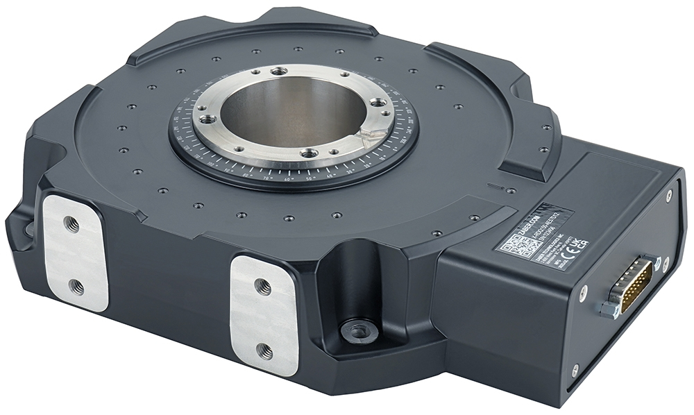
Precision, High Speed Direct Drive Rotary Stages with Direct Encoders
Disclaimer
Zaber’s products are not intended for use in any critical medical, aviation, or military applications or situations where a product's use or failure could cause personal injury, death, or damage to property. Zaber disclaims any warranty of fitness for a particular purpose. The user of this product agrees to Zaber's general terms and conditions of sale.
Precautions
Zaber's autodetect peripheral axes are designed to be used effortlessly with Zaber's line of autodetect controllers. The RDQ-AE includes onboard memory that allows Zaber's controllers to autodetect the model and set reasonable parameters. See the Protocol Manual for more information on how to modify the settings. Damage to the axis may result if the settings are not correct. To use your Zaber peripheral with a third-party controller, review the motor, sensor, and encoder specifications and pin-outs carefully.
Important Precautions for Use
Contamination could impact the performance of the RDQ-AE stage. Avoid introduction of ferro-magnetic particles to the stage, and contact with, or contamination of, the encoder scale.
 Mounting and Maintenance Hazard! For operator safety, the RDQ-AE should always be un-powered during all cleaning, maintenance, and stage or load mounting operations. A powered stage could exert high forces and move at high speeds very suddenly if accidentally given a move command.
 Strong Magnets! The RDQ-AE stages contain strong magnets that could affect pacemaker function. Pacemaker users should stay at least 20 cm away from the stages. The magnets can also attract nearby magnetic objects.
Secure Stage Mounting Required! The RDQ-AE stages can shake and vibrate during operation due to high inertia. The stages must always be securely mounted to a work surface during operation. See #Physical_Installation for information on stage mounting.
 Important: The RDQ-AE stage should be homed immediately upon power-up. Behavior may appear jerky during homing. Once the stage has been homed, motion will be controlled and smooth.
Back-driving Hazard! Linear motor stages require current to the motor coils to provide a force to maintain position and/or support a load. If power is removed the carriage may move suddenly or in an uncontrolled manner. The RDQ-AE stage is not intended for load lifting operations due to the risk of uncontrolled motion if driver power is removed.
Important: The RDQ-AE is a servo device, meaning that its performance is dependent on proper tuning of the servo parameters for the given load. The use of incorrect servo parameters may reduce the device’s performance in operation. Incorrect tuning may also result in unstable operation, which can cause unexpected rapid motion of the device, leading to reduced device lifetime and user injury. When the operating load on the device is changed, the tuning parameters should be updated to match. For details see the servo tuning guidelines.
 Caution. The motor in the RDQ-AE can exceed 60° C if the device is not properly mounted. For continuous duty cycle applications, we recommend mounting the stage to an aluminum heat sink of at least 300mm x 300mm x 10mm3
Lubrication and Cleaning
Under normal operation of the stage, the bearing will not require lubrication or maintenance for the life of the stage. In applications that use only a portion of travel, its important to drive the stage through its full travel every 1000 hours of operation to redistribute the grease in the bearings.
Noise Emissions
The A-weighted emission sound pressure level (SPL) of this device does not exceed 70 dB(A) during intended use.
Conventions used throughout this document
- Fixed width type indicates communication to and from a device. The
 symbol indicates a carriage return, which can be achieved by pressing enter when using a terminal program.
Device Overview
AutoDetect
Your RDQ-AE peripheral is equipped with AutoDetect, a feature that allows a Zaber controller to automatically configure its settings for the peripheral when it is connected.
Important: The controller should always be powered down before disconnecting or connecting your RDQ-AE peripheral.
To connect the peripheral to a controller:
- Power off the controller.
- Connect the RDQ-AE peripheral.
- Power on the controller.
- The controller will activate the peripheral shortly after it is powered on.
See the Zaber controller user manual for more details on peripheral activation and control.
Connectors
Recommended controller(s) for your RDQ-AE peripheral are provided in the product specifications. Zaber's controllers and peripherals are designed for ease of use when used together. Optimal settings for each peripheral are automatically detected by Zaber's controllers when the device is connected.
For reference, the pinout for the peripheral cable connectors is shown below:
Pinout for D-sub 26 Connectors (peripherals)
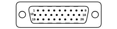
Male High Density D-sub26 Connector |
Pin | Description | Pin | Description |
|---|---|---|---|---|
| 1 | AutoDetect Clock | 14 | Motor Hall C | |
| 2 | AutoDetect Data | 15 | +5V | |
| 3 | N.C. | 16 | Ground | |
| 4 | N.C. | 17 | N.C. | |
| 5 | N.C. | 18 | Motor W | |
| 6 | Motor Over-Temperature | 19 | Differential Encoder Sin- | |
| 7 | Ground | 20 | Differential Encoder Cos- | |
| 8 | Motor V | 21 | Differential Encoder Index- | |
| 9 | Motor U | 22 | Motor Hall A | |
| 10 | Differential Encoder Sin+ | 23 | Motor Hall B | |
| 11 | Differential Encoder Cos+ | 24 | N.C. | |
| 12 | Differential Encoder Index+ | 25 | N.C. | |
| 13 | Differential Encoder Error | 26 | N.C. |
NOTE: All hall sensor signals (for limits or motor phase) are open collector and require a pull-up on the controller.
NOTE: All single-ended encoder inputs are non-isolated 5V TTL lines.
NOTE: All differential encoder signals are non-isolated, and must be terminated on the controller with 120 Ω. For -AE peripherals, these signals are sinusoidal with 1 V peak-to-peak differential levels and with the common mode between 1.5 V and 2.5 V.
Alternate Controllers
The RDQ-AE can be controlled by other linear motor controllers with appropriate encoder input. We do not recommend using your own controller unless you are familiar with wiring and tuning third-party linear motor products. Damage to the device due to incorrect wiring is not covered by warranty.
Motors & Encoders
For motor and encoder information see the RDQ-AE product page
Installation
The RDQ-AE can be operated by connecting to the controller/s recommended in the product specifications. Please review the controller's user manual as well.
Physical Installation
Tip: To obtain the best runout, tilt, and accuracy performance, mount the stage to a known flat, stiff surface. Our tests were performed on a granite surface plate, grade A flatness.
Stability Hazard! Ensure the stage is fastened to a secure surface before mounting a load on the carriage. Ensure loads are mounted securely to the carriage of the stage before operating.
Mounting and Maintenance Hazard! For operator safety, the RDQ-AE should always be un-powered during all cleaning, maintenance, and stage or load mounting operations. A powered stage could exert high forces and move at high speeds very suddenly if accidentally given a move command.
Caution. The motor in the RDQ-AE can exceed 60° C if the device is not properly mounted. For continuous duty cycle applications, we recommend mounting the stage to an aluminum heat sink of at least 300mm x 300mm x 10mm3
Mounting
RDQ-AE stages are designed to be secured using 4 metric or imperial socket cap screws. The following screw sizes should be used:
- Metric: M6 screws, 20mm or longer
- Imperial: 1/4 screws, 7/8" or longer
The stages can also be mounted on one of two sides using the 4x M6 threaded holes provided. Take care to select the correct length screw for your application to avoid bottoming out the in the housing threaded holes, as this can damage the device.
AP270/AP271 Installation


Tools Required
- 2.5 mm hex key
Fasteners Provided
- 6x M3 x 8 mm screws
RDQ-AE - AP270/271 Installation

- If applicable, place the hard stops (AP271) where restricted travel is required
- Hard stops travel is configurable in 15 degree increments. This example shows +60 degrees (CW) and -165 degrees (CCW) from the zero position
- Take note of the location of the alignment key on the bottom of AP270 stage top.
- Flip it over and align the key with the notch in the RDQ-AE spindle. Ensure the notch is facing forward inline with the zero index on the stage
- Slide the AP270 stage top onto the spindle and insert the the 6x screws. Tighten the screws in a star pattern.
If using updating the hardstop positions, use the tools findrange hardstop command to update the travel limits of the device before operating.
Trajectory Control and Behaviour
This section describes the behaviour of the axis trajectory when a movement command is issued.
Software Position Limits
The travel range of the axis is limited by the Minimum Position and Maximum Position settings. The factory settings for the axis are configured to match the physical travel range. If a customized range is desired, it can be changed by configuring the limit.min and limit.max settings to appropriate values. For the Current Position, query pos.
- Minimum Position
- When the Current Position is less than the Minimum Position value, the axis cannot move in the negative direction.
- Maximum Position
- When the Current Position is greater than the Maximum Position value, the axis cannot move in the positive direction.
Movement Speed
The movement speed of the axis depends on axis status and various speed settings. If the axis has not been initialized by the home command or by moving towards the home end of the axis, movement speed will be constrained to fail-safe values. The home status of the axis can be determined by reading the limit.home.triggered setting.
Movement speed of the axis is specified below:
- move vel
- The axis will move at the specified speed regardless of home status.
- Knob movement in Velocity Mode
- The axis will move at the specified speed regardless of home status.
- The speed is specified by the knob.speedprofile and knob.maxspeed settings.
- Other movement commands - when the axis has not been homed
- The axis will move at the slower of the maxspeed and limit.approach.maxspeed settings.
- Other movement commands - when the axis has been homed
- The axis will move at the speed specified by the maxspeed setting.
Warranty and Repair
For Zaber's policies on warranty and repair, please refer to the Ordering Policies.
Standard products
Standard products are any part numbers that do not contain the suffix ENG followed by a 4 digit number. Most, but not all, standard products are listed for sale on our website. All standard Zaber products are backed by a one-month satisfaction guarantee. If you are not satisfied with your purchase, we will refund your payment minus any shipping charges. Goods must be in brand new saleable condition with no marks. Zaber products are guaranteed for one year. During this period Zaber will repair any products with faults due to manufacturing defects, free of charge.
Custom products
Custom products are any part numbers containing the suffix ENG followed by a 4 digit number. Each of these products has been designed for a custom application for a particular customer. Custom products are guaranteed for one year, unless explicitly stated otherwise. During this period Zaber will repair any products with faults due to manufacturing defects, free of charge.
How to return products
Customers with devices in need of return or repair should contact Zaber to obtain an RMA form which must be filled out and sent back to us to receive an RMA number. The RMA form contains instructions for packing and returning the device. The specified RMA number must be included on the shipment to ensure timely processing.
Email Updates
If you would like to receive our periodic email newsletter including product updates and promotions.
Contact Information
Contact Zaber Technologies Inc by any of the following methods:
| Phone | 1-604-569-3780 (direct) 1-888-276-8033 (toll free in North America) |
|---|---|
| Fax | 1-604-648-8033 |
| #2 - 605 West Kent Ave. N., Vancouver, British Columbia, Canada, V6P 6T7 | |
| Web | www.zaber.com |
| Please visit our website for up to date email contact information. |
The original instructions for this product are available at https://www.zaber.com/manuals/RDQ-AE.
Appendix A: Default Settings
Please see the Zaber Support Page for default settings for this device.
Product Drawing
Specifications
| Specification | Value | Alternate Unit |
|---|---|---|
| Built-in Controller | No | |
| Recommended Controller | MCC (48 V) Recommended | |
| Range | 360° | |
| Accuracy (unidirectional) | 0.006° | 0.104700 mrad |
| Minimum Incremental Move | 0.0000115° | 0.20 µrad |
| Repeatability | < 0.0001° | < 0.002 mrad |
| Maximum Speed | 2700°/s | 450 rpm |
| Encoder Count Size | 0.0000027778°/count | 0.010 arcseconds/count |
| Minimum Speed | 0.0000027778°/s | 0.048 µrad/s |
| Encoder Resolution | 16200 CPR | 64800 states/rev |
| Encoder Type | Direct Reading Optical Encoder | |
| Maximum Torque | 7.8 N⋅m | 5.756 lb⋅ft |
| Maximum Continuous Torque | 2 N⋅m | 1.476 lb⋅ft |
| Maximum Centered Load | 100 N | 22.4 lb |
| Maximum Moment (Tilt) | 4 N⋅m | 2.952 lb⋅ft |
| Stage Top Dimension | 70 mm | 2.756" |
| Radial Error Motion | +/- 3 µm | +/- 0.000118" |
| Axial Error Motion | < 3 µm | < 0.000118" |
| Tilt Error Motion | +/- 0.0014° | +/- 24.43 µrad |
| Bearing Plane Offset | 16.5 mm | 0.650" |
| Aperture Diameter | 50.8 mm | 2.000" |
| Stiffness (Tilt) | 1300 N⋅m/° | 13.4 µrad/N⋅m |
| Motor Type | Moving Magnet Track Rotary Motor (3 phase) | |
| Motor Rated Current | 3000 mA | |
| Motor Winding Resistance | 2.4 ohms line-to-line | |
| Motor Winding Inductance | 0.34 mH line-to-line | |
| Motor Connection | D-sub 26 | |
| Motor Rotor Inertia | 0.00513 kg⋅m2 | |
| Mechanical Drive System | Direct Drive | |
| Limit or Home Sensing | Optical Index Mark | |
| Mounting Interface | M3 and M6 Threaded Holes and M6 Mounting Holes | |
| Torque Constant | 0.65 N⋅m/A | 0.480 lb⋅ft/A |
| Operating Temperature Range | 0-40 °C | |
| CE Compliant | Yes | |
| Vacuum Compatible | No | |
| Weight | 3.187 kg | 7.026 lb |
Charts and Notes
.gif)