TwinCAT3 Setup Guide
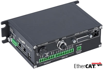
Table of Contents
Table of Contents
Preamble
The following guide will assist with setting up a Zaber E-MCC series controller/drive in TwinCAT 3.
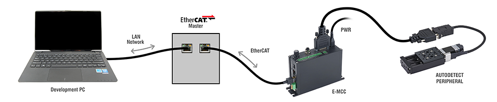
Prior to configuring TwinCAT for your E-MCC, it is important to make sure that your physical setup is complete and that TwinCAT 3 is installed and configured on your development computer.
Hardware Setup
Your hardware should all be physically plugged in prior to setting up the E-MCC in TwinCAT.
This includes:
- a peripheral stage plugged into the E-MCC
- the peripheral stage being activated
- Note: This occurs automatically the first time a Zaber peripheral is plugged into the E-MCC.
- the EtherCAT cable is connected
- the Power supply is connected
- the Development PC is connected to the EtherCAT master.
- Note: It is possible to install the TwinCAT development environment (XAE) directly on the EtherCAT master. In this case a development PC is not required. See TwinCAT XAE and XAR.
TwinCAT Installation
If not already installed, download and install TwinCAT 3 on your development computer.
- Note: This guide is written using TwinCAT 3 build 4026, but the process will be very similar for older versions such as build 4024.
ESI File Installation
- Download the ESI file from the product webpage.
- Copy the ESI file to the appropriate folder.
- By Default, this folder is located in the TwinCAT installation directory.
- Typically C:\Program Files (x86)\Beckhoff\TwinCAT\3.1\Config\Io\EtherCAT
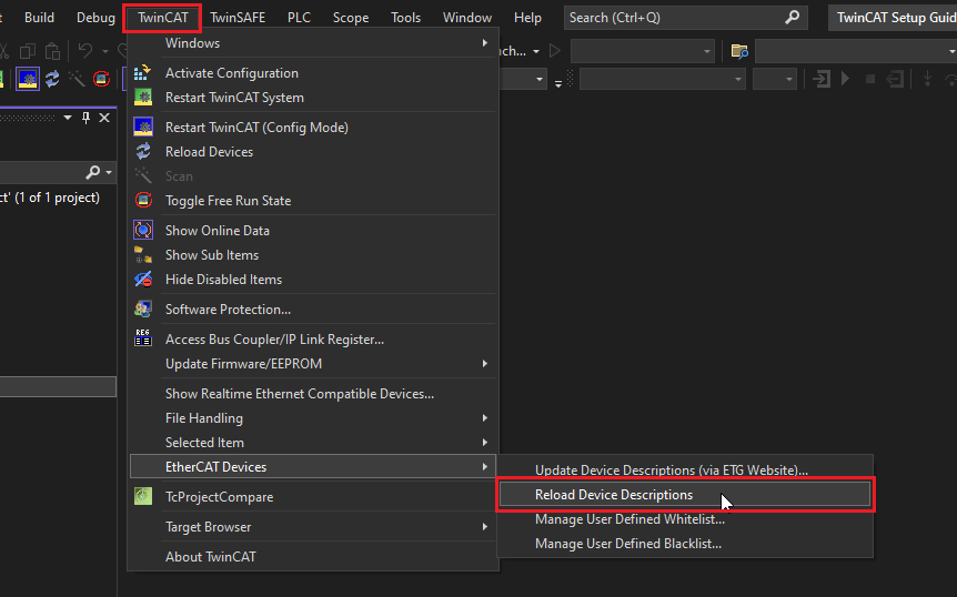
- If TwinCAT is already open, reload the ESI files.
- Select
TwinCAT -> EtherCAT Devices -> Reload Device Descriptions - Note: This menu is only available if a project is open.
- Note: TwinCAT automatically performs this action at startup.
- Select
TwinCAT XAE Project Setup
The following instructions detail how to set up a TwinCAT XAE project which can perform point-to-point (PTP) motion using the E-MCC.
Initial Setup
- Open the TwinCAT XAE shell.

- Select
File -> New -> Project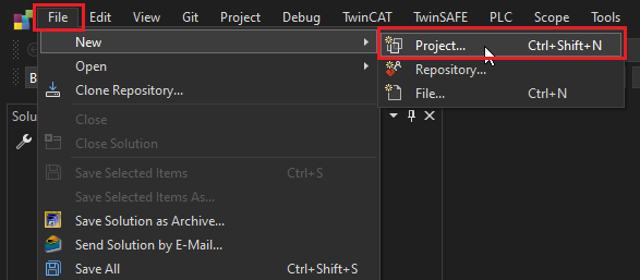
- Create a new
TwinCAT XAE Project (XML Format).- Create the project with the name and folder of your choice.

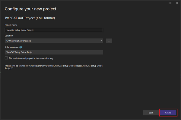
- Create the project with the name and folder of your choice.
- Ensure that the TwinCAT XAE is connected to the XAR on your Beckhoff IPC.
- If you haven’t previously added your IPC, see Setting up a New Target System.
- If you’re running the TwinCAT XAE directly on the IPC, select
<Local>.
- Ensure that TwinCAT is in Config Mode.
- The blue icon on the bottom status bar confirms that Config Mode is active.
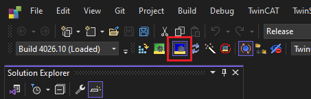
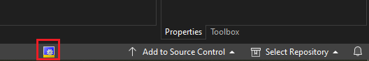
- The blue icon on the bottom status bar confirms that Config Mode is active.
IO Tree Setup
The I/O tree represents the physical devices on the EtherCAT network. TwinCAT needs to know the layout of devices on the network prior to initializing it. A typical network configuration is one EtherCAT master with multiple slaves connected to it.
To set up the I/O tree with the E-MCC:
- Expand the
I/Otree. - Right click on
Devices -> Add New Item....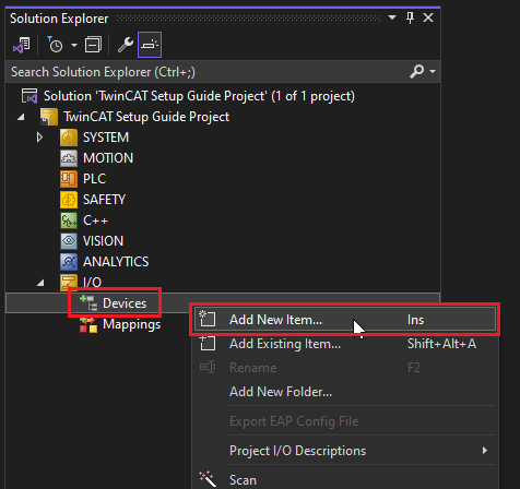
- Select
EtherCAT Masterand clickOk.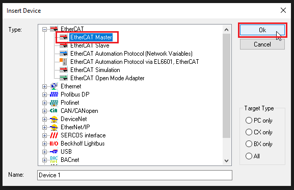
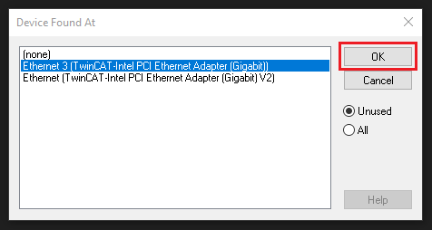
- Select whichever network adapter you intend to be your EtherCAT master.
- For Beckhoff IPCs these are usually labelled on the device as X000, X001, etc.
- Note: Network adapters must have the correct driver installed or they won’t show up on the list. If the adapter isn’t listed, see Setting up a Network Adapter.
- Once your network adapter is configured, right click on the EtherCAT master and click
Scan.- This will attempt to find all EtherCAT slaves connected to the network adapter.
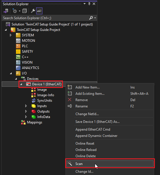
- This will attempt to find all EtherCAT slaves connected to the network adapter.
- When prompted, click
OKto append the linked axis inNC - Configuration.- This window appears because a CiA 402 compatible drive was found on the network.
- Note:
CNC - Configurationis out of the scope of this guide.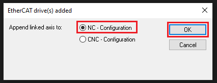
- An E-MCC should appear underneath the master, along with any other connected slave devices.
- Additionally, an NC Axis (Axis 1) should appear under the
MOTIONtree.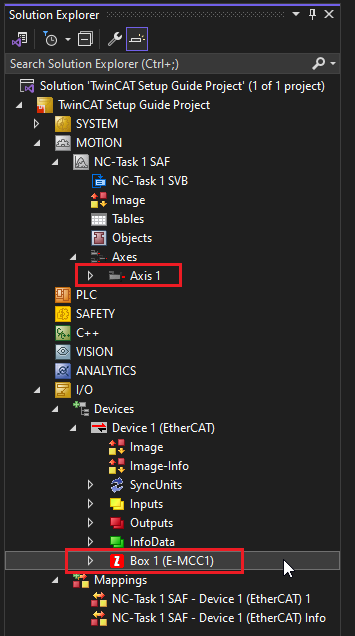
- Additionally, an NC Axis (Axis 1) should appear under the
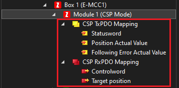
- Expand the E-MCC1 to view its default process data (PDOs).
- This is the real time data sent over the EtherCAT network:
- Red items are output data sent from Master to Slave (RxPDO).
- Yellow items are input data returned from Slave to Master (TxPDO).
- Green items are generic network diagnostic/configuration information.
- If you wish to change this data, see Configuring Process Data.
- Note: For peripherals without an encoder, it is highly recommended to remove
Position Actual ValueandFollowing Error Actual Value, since these values are invalid without a position feedback sensor.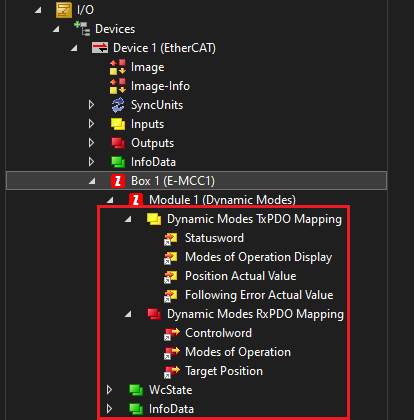
- This is the real time data sent over the EtherCAT network:
- Double click the E-MCC1 and open the
DCtab.- Click
Advanced Settings…to open the advanced distributed clock settings.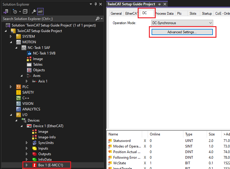
- Click
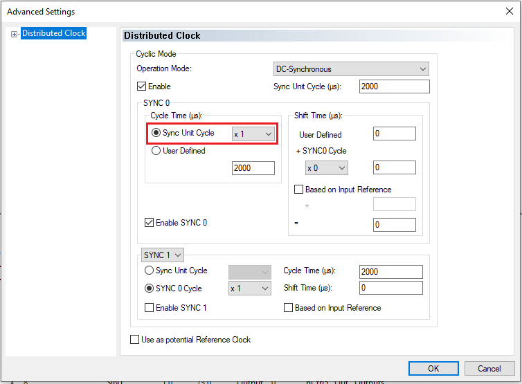
- Ensure the
Sync Unit Cycleis set to 1x.- This ensures that the Sync0 signal fires once for every master trajectory setpoint.
- Note: The E-MCC uses the Sync0 signal to calculate trajectory interpolation. Setting this field incorrectly may cause jerky motion.
NC Axis Setup
The NC Axis generates point-to-point motion trajectories on the EtherCAT master. These trajectories are streamed to the drive as individual setpoints via real-time EtherCAT process data (PDOs). The following instructions outline how to configure the NC Axis for use with the E-MCC. For more information see Beckhoff's TF50x0 | TwinCAT 3 NC PTP Manual.
Setting up an NC Axis involves three primary steps:
These steps are detailed below.
Timing Settings
Timing settings determine the rate at which NC Axis trajectories are calculated and streamed to the drive. There are two separate tasks:
- NC-Task 1 SAF - The rate at which individual trajectory points are transmitted over the EtherCAT network.
- NC-Task 1 SVB - The rate at which the whole trajectory is evaluated for re-calculation.
Increasing these rates is generally beneficial for motion performance, but also increases CPU usage on the master. Usually the SVB task can be left at the default value. However, it is important to set the NC-Task 1 SAF to a rate supported by the drive because this value determines the EtherCAT process data cycle rate.
To set the cycle rate:
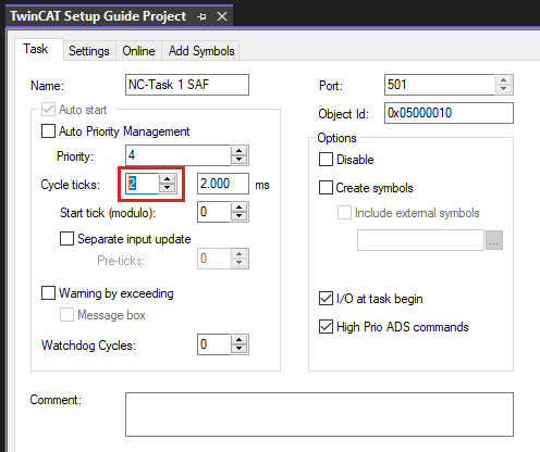
- Select the
NC-Task 1 SAF.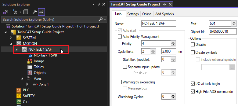
- If the current
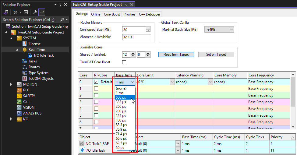
Cycle ticksare not within the valid range supported by the E-MCC, adjust the value.- The E-MCC supports rates from 1.0 ms to 10.0 ms.
- 1.0 ms will result in the best motion performance.
- Note: Cycle ticks cannot be set lower than the system base time. See Configuring System Base Time if you need to change this value.
General Settings
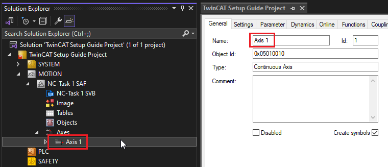
There are a few general settings that are important to configure on an NC-Axis.
- Double click the NC Axis.
- Tip: It’s a good practice to name it something useful (ex. X-Axis).
- Tip: It’s a good practice to name it something useful (ex. X-Axis).
- Select the
Settingstab. Ensure the NC Axis is linked to the desired physical hardware on theI/Otree.- This ensures that process data is transmitted between the NC Axis and the drive.
- Note: If the box is empty, click
Link To I/O…and select the E-MCC.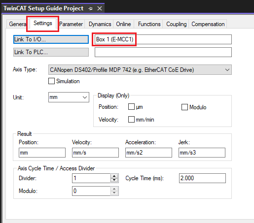
- Ensure the Axis Type is
CANopen DS402/Profile MDP 742 (e.g. EtherCAT CoE Drive), and select the units of your choice.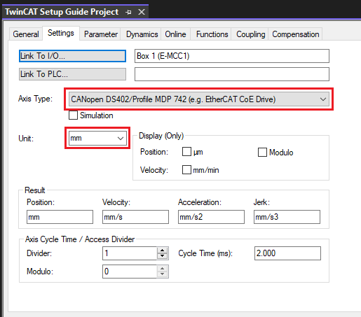
Parameters
The NC Axis has limited information about the E-MCC. Therefore, certain parameters must be configured to ensure the NC Axis generates trajectories that are suitable for the connected peripheral. These settings include:
- Scaling factor (unit conversion factor)
- Maximum speed
- Jog speeds
- Acceleration limits
- Travel limits
- Following error monitoring
Note: Some steps in the following section involve querying Zaber specific settings from your device. We recommend using our free software, Zaber Launcher for this purpose.
To set these parameters:
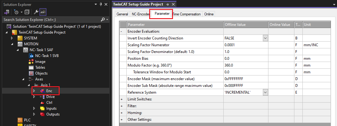
- Expand the NC Axis. Click
ENC, then select theParametertab.- These parameters relate to the device’s encoder.
- These parameters relate to the device’s encoder.
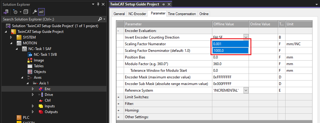
- Under
Encoder Evaluation, set theScaling Factor NumeratorandDenominatoras required for the connected peripheral.- Scaling factors are the most important settings for an NC Axis. They determine the conversion ratio from native position units to user units (m, mm, deg, etc.).
- Zaber devices use the following native units:
- Stepper motor axes use native units of microsteps, as indicated by the Microstep Size specification.
- Servo (linear motor) axes use native units of encoder counts, as indicated by the Encoder Count Size specification.
- Set the scaling factors based on your chosen user units and microstep or encoder count size of your peripheral. The value can be found on the product’s webpage, under specifications. The scaling factors shown below are for a servo device with an encoder count size of 1 nm (1,000,000 counts per mm, or 0.001/1000.0 mm/INC).
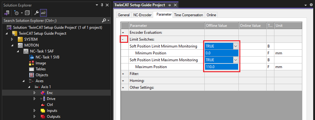
- Under
Limit Switches, set the following parameters: - For non-encoder peripherals only: Select the
NC-Encodertab and set the type toSimulation encoder.- Simulation encoder means that the NC Axis measured position is obtained by directly copying target position values. A real measured position can only be obtained on devices with an encoder.
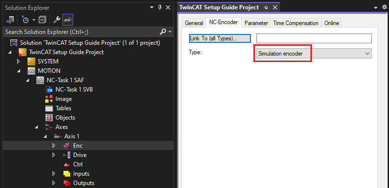
- Simulation encoder means that the NC Axis measured position is obtained by directly copying target position values. A real measured position can only be obtained on devices with an encoder.
- Under the NC Axis, select
Ctrl, then theNC-Controllertab.- Ensure that the type is set to
SERCOS controller (Position by SERCOS). - This ensures that generated trajectory values get sent directly to the drive without filtering.
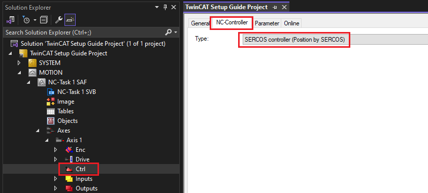
- Ensure that the type is set to
- Under the
ParameterTab, verify theMonitoringparameters.Position Lag Monitoringwill cause the NC Axis to fault if the specified lag distance is exceeded (target position - measured position).Position Lag Monitoringshould typically be TRUE, unless:- Your peripheral does not have an encoder.
- You have unusual application specific requirements.
- Set the
Maximum Position Lag Valueto be suitable for your application (often 1-2 mm/deg).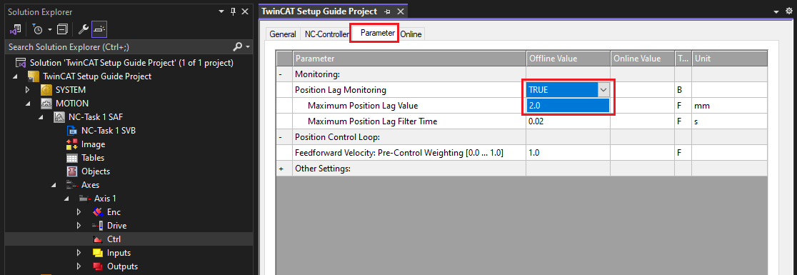
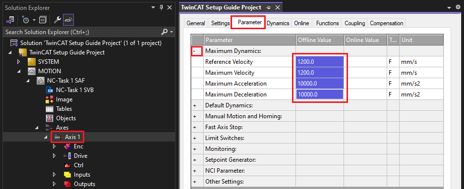
- Select the NC Axis, then the
Parametertab. Set the followingMaximum Dynamicsparameters:Reference Velocity: The peripheral’s maximum speed specification.Maximum Velocity: Same as reference velocity.Maximum Acceleration: Calculate this based on your payload and device’s peak thrust specification (acceleration = thrust / mass).Maximum Deceleration: Typically the same as Maximum Acceleration.- Note: Make sure you query Zaber settings in the same units as TwinCAT (ex. mm/s).
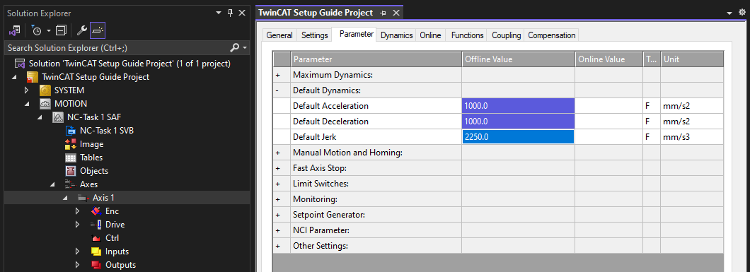
- Under
Default Dynamics, set the following parameters:Default Acceleration: Zaber’s accel settingDefault Deceleration: Typically the same as Default AccelerationDefault Jerk: Your choice. A typical value is 4x acceleration. Lower values produce smoother motion, but may take longer to execute a trajectory.- Note: Make sure you query Zaber settings in the same units as TwinCAT (ex. mm/s2).
- Under
Manual Motion and Homing, set theManual VelocityandJog Increments.- These parameters are optional, as they control the behavior of TwinCAT’s NC Axis Online window. Set them to values that are useful for testing the motion of your device.
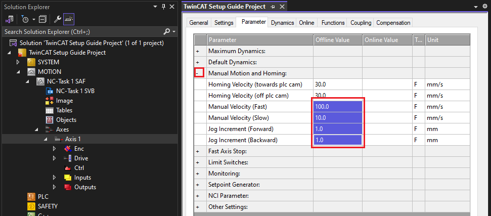
- These parameters are optional, as they control the behavior of TwinCAT’s NC Axis Online window. Set them to values that are useful for testing the motion of your device.
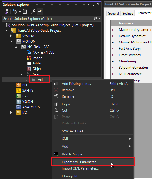
- Tip: To save your settings for future use, right click on the NC Axis and select
Export XML Parameter....- Your NC Axis parameters can be easily loaded from this file in the future.
- Save the file as a useful name for the device (ex. LDM110C-AE54T10A.xml).
Testing Motion
Once the I/O tree and NC Axis have been configured, everything should be ready to perform motion with your E-MCC.
To test that motion is working properly:
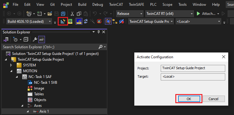
- Click
Activate Configuration.- When prompted to
Restart in Run Mode, clickOK. - This tells the TwinCAT XAR to activate and run the configuration you’ve created in the TwinCAT XAE project.
- When prompted to
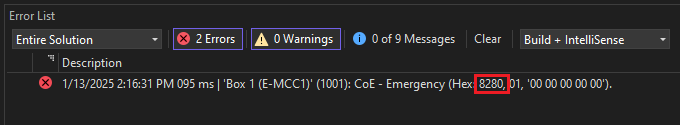
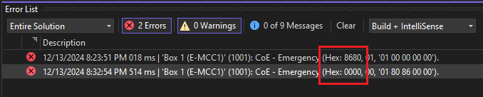
- You may see the following emergency message:
Hex: 8280.- This error indicates that one of your assigned process data objects is not supported by the peripheral connected to the E-MCC.
- The most common reason for this error is that an non-encoder peripheral is connected to the E-MCC. Objects 0x6064 Position Actual Value and 0x60F4 Following Error Actual Value should be removed from the process data configuration, as these values are not valid without a position feedback sensor.
- See Configuring Process Data.
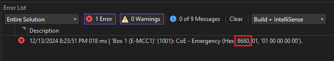
- You may see the following emergency message:
Hex: 8680.- This error means the axis hasn’t been homed yet.
- Please home the axis before proceeding.
- See Homing an Axis.
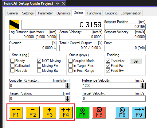
- Double click the NC Axis. Select the
Online Tab, then click theF8reset button.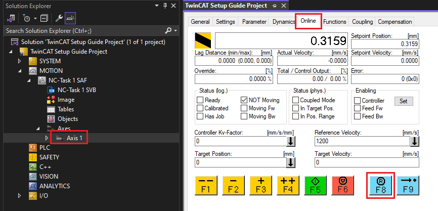
- Click
Set. In the popup window clickAll.- This will enable the motor.
- The
Allbutton activates all three checkboxes and sets the velocity override to 100%.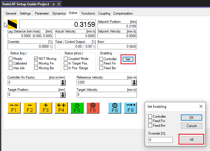
- Use the jog buttons to move your device around and test that motion works properly.
- If the axis encounters a fault (ex. Following Error), press the
F8reset button to reset the NC Axis.
PLC Project Setup
A PLC project is used for writing automated PLC programs. These programs can interact with the NC Axis and thus control motion on the E-MCC. Below are the basic steps for building a TwinCAT PLC program that can interact with the E-MCC using Beckhoff’s Tc2_MC2 motion library. The library contains many function blocks which can be used to interact with the NC Axis. For more information, see the Tc2_MC2 Manual.
Note: TwinCAT’s MC_Home function block will not work properly with the E-MCC. For information on homing, see Homing From a PLC Project.
The following instructions assume you have already set up your TwinCAT XAE project as documented in the previous sections.
To create a PLC project:
- Right click on
PLCand selectAdd New Item….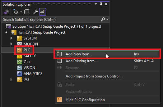
- Add a new
Standard PLC Projectwith the name of your choice.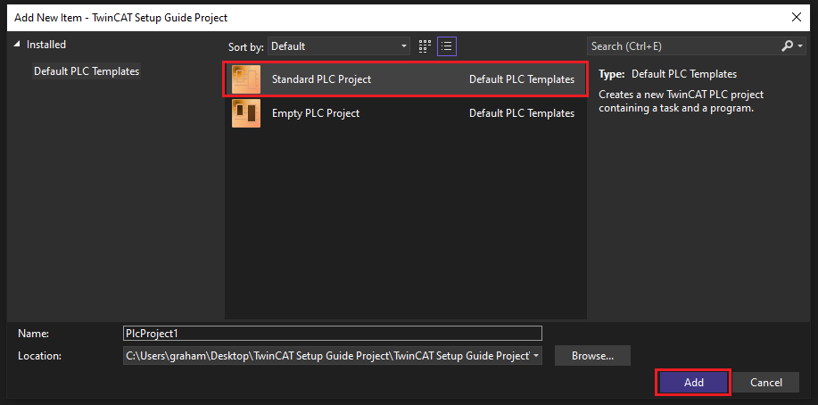
- Expand the project. Right click on
Referencesand selectAdd library….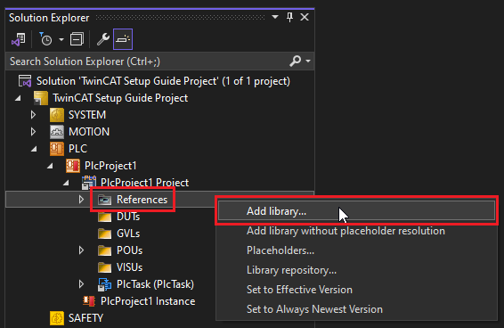
- Add the
Tc2_MC2andTc2_NClibraries to your project.- Only one library can be added at once.
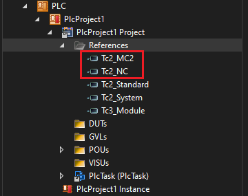
- Once added, both libraries should be visible under
References.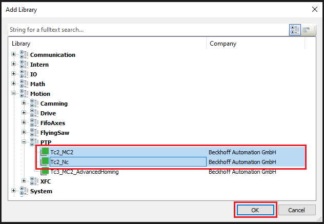
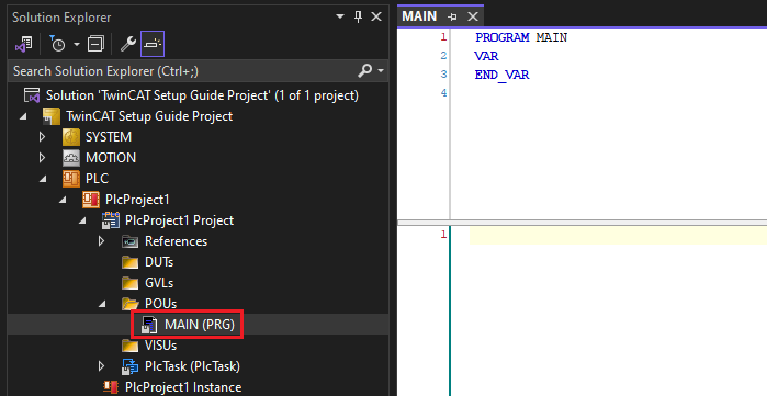
- Expand the
POUsfolder and double clickMAIN (PRG).- This file is the primary execution point of your PLC program.
- This file is the primary execution point of your PLC program.
- Add a variable of type
AXIS_REFto the program.- The
AXIS_REFvariable provides an interface between the PLC program and NC Axis.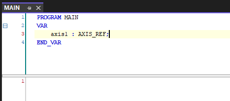
- The
- Click
Build -> Build Solutionto compile the program.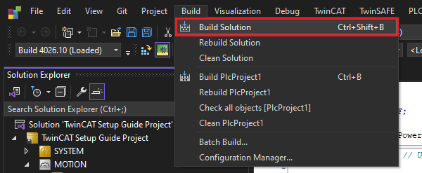
- Expand the
MOTIONtree and double click the NC Axis. In theSettingstab, clickLink To PLC…. Select theMAIN.axis1variable from your PLC project and clickOK.- This links the NC Axis to your
AXIS_REFvariable. - Since the NC Axis is also linked to the E-MCC, motion can be directly controlled from the PLC program.
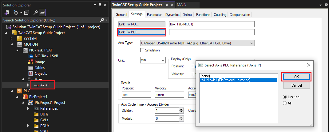
- This links the NC Axis to your
- Add the
MC_Powerfunction block variable to the program, and the following lines of code as shown below.axis1.ReadStatus()is not required, but is a good practice to call at the start of all PLC programs. It updates the internal state of theAXIS_REFfunction block.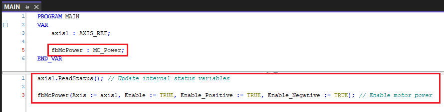
- Re-compile the PLC program.
- Click
Activate Configurationand restart TwinCAT in Run Mode.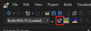
- Click
Login, thenYeson the popup dialog.- This enables access to view and control code execution on the PLC.
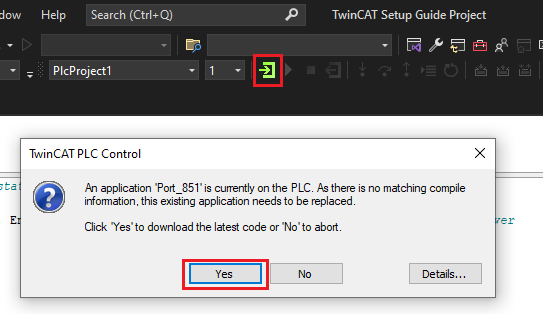
- This enables access to view and control code execution on the PLC.
- Click
Startto start execution of the PLC program.- This should enable motor power on the E-MCC.
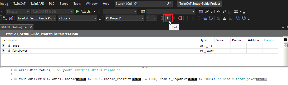
- This should enable motor power on the E-MCC.
- The real-time status of the NC Axis can be viewed by expanding the
axis1variable.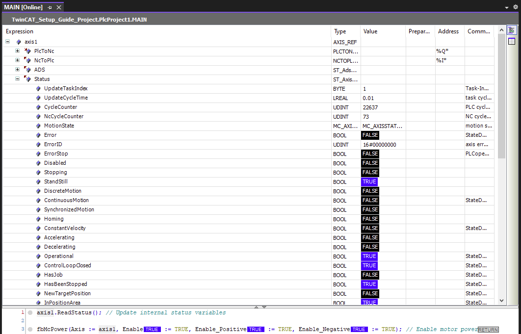
- To stop the program execution, press
Stop, followed byLogout.- This will disable the motor power.
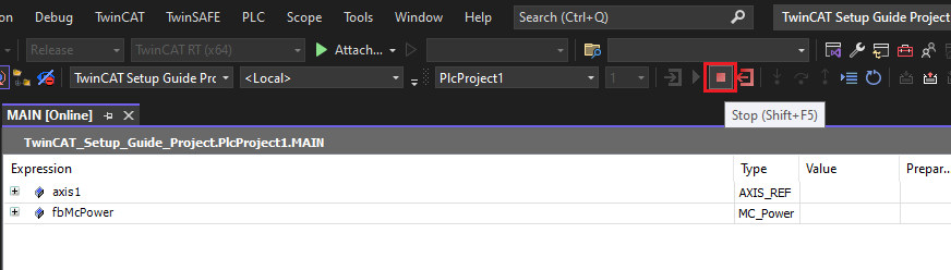
- This will disable the motor power.
At this point, initial setup is complete.
Example Projects
This section contains TwinCAT3 example projects available for download.
Can't find what you're looking for? If there's a different type of example you'd like to see here, please contact us.
Drive Based Homing Example
This example demonstrates how to perform drive based homing (CiA 402 operation mode 6) from a TwinCAT PLC program. For more information see Homing From a PLC Project.
- Download: Zaber TwinCAT Homing Example.zip
Basic Motion Example
This example demonstrates how to use basic drive functionality and perform point-to-point motion from a TwinCAT PLC program.
- Download: Zaber TwinCAT Basic Motion Example.zip
Appendix
This section contains optional steps and reference information about TwinCAT.
TwinCAT XAE and XAR
TwinCAT consists of two independent software packages:
- eXtended Automation Engineering (XAE)
- This is the TwinCAT development environment, which is based on a modified version of Visual Studio. It is used for tasks like configuring the EtherCAT network, writing PLC programs, and testing motion.
- The XAE has an unlimited free license.
- eXtended Automation Runtime (XAR)
- This software is what makes a computer an EtherCAT master. It runs the EtherCAT network and executes user generated code in soft real-time.
- The XAR has unlimited free 7-day trial licenses. A CAPTCHA has to be entered every 7 days to continue operation.
The most common TwinCAT setup is to have the XAR installed on a Beckhoff IPC (industrial PC) and the XAE installed on the user’s development PC. The two software packages communicate over Ethernet using Beckhoff’s proprietary protocol, ADS. PLC programs and network configuration are generated in the XAE, and then pushed to the XAR (activated) using ADS. However, another common configuration is to install both the XAE and XAR on the same computer. This guide is valid regardless of whether the XAR is installed on the local computer or a remote computer.
For more information, see Beckhoff’s documentation: TwinCAT 3 Philosophy.
Setting up a New Target System
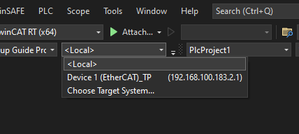
The TwinCAT XAE development environment can remotely connect to TwinCAT runtime environments on a network attached computer or IPC, also known as the target system. The desired target system can be selected from the dropdown menu shown below in TwinCAT. However, the remote machine will not show up on this list unless you’ve configured it first. The instructions below show how to set up a new target system.
Note: Ensure both your development computer and remote machine are physically connected to the same Local Area Network (LAN) before proceeding. If a LAN network is not available, it is also possible to connect two computers with a single Ethernet cable. To connect computers with a single cable, you must set static IP addresses on the network adapters of both computers. It is recommended to set your development machine’s IP to 192.168.1.1 and the remote machine’s IP to 192.169.1.2.
To set up a new target system:
- Open the dropdown menu and select
Choose Target System.... - In the popup menu, select
Search (Ethernet)....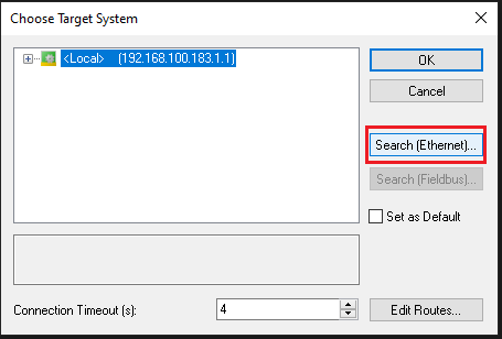
- Click
Broadcast Search.- This will search the LAN network for remote computers with the TwinCAT runtime installed.
- Note: Occasionally the broadcast search will not find any devices. In this case, connect a mouse and monitor to the remote machine and manually check its network IP address, or use third party network scanning software to scan all the IP addresses on your network. The IP address can be entered manually in the upper text field, followed by clicking
Enter Host Name / IP.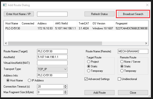
- Select the desired machine and click
Add Route.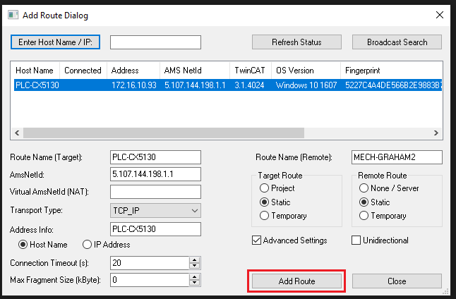
- Enter the
UserandPasswordfor the remote machine and clickOK.- This is typically the user’s Windows account credentials.
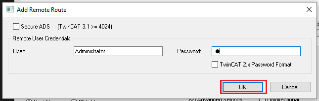
- This is typically the user’s Windows account credentials.
- The device should appear as connected, indicated by the checkmark. Click
Closeto close the window.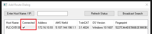
- Select your new target system and click
OK.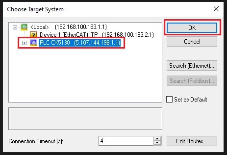
- Your new target system should now be selected in the dropdown menu. This means TwinCAT is successfully connected to the remote machine.
- The target system’s mode (Run or Config) should also be visible on the bottom toolstrip.
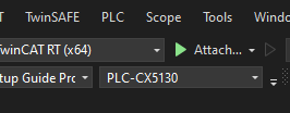
- The target system’s mode (Run or Config) should also be visible on the bottom toolstrip.
With the new target system setup, you are ready to configure your remote machine.
Setting up a Network Adapter
Network Interface Controllers (NICs) need a specific real-time driver installed before they can be used with TwinCAT. These drivers come pre-installed on Beckhoff IPCs, but may have to be installed manually for other systems. Note that only certain network adapters are compatible with TwinCAT. See Supported network controllers.
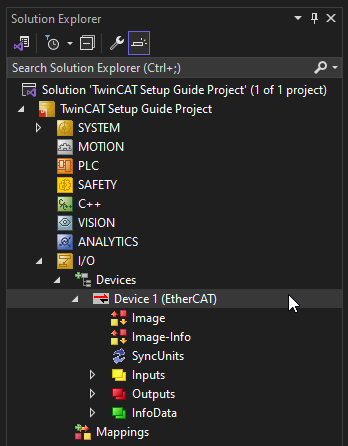
To set up a network adapter:
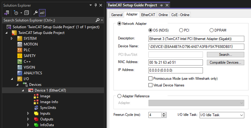
- Double click your EtherCAT master on the I/O Tree.
- Navigate to the
Adaptertab and selectCompatible Devices...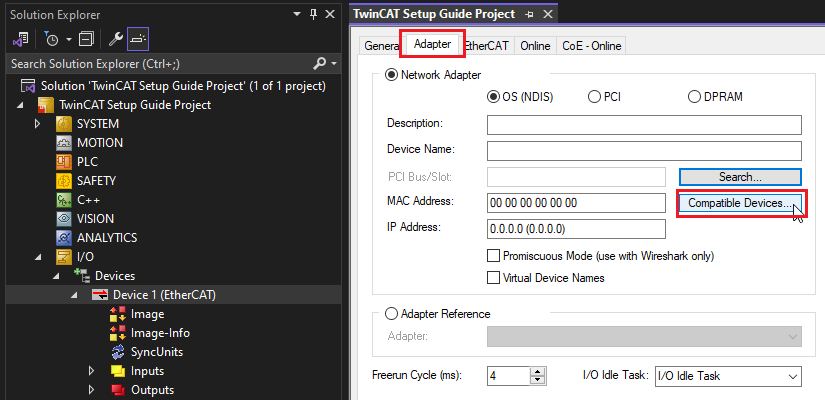
- Select your desired network adapter and click
Install.- The adapter must appear under the
Compatible devicessection. If the adapter is listed underIncompatible devices, it cannot be used with TwinCAT.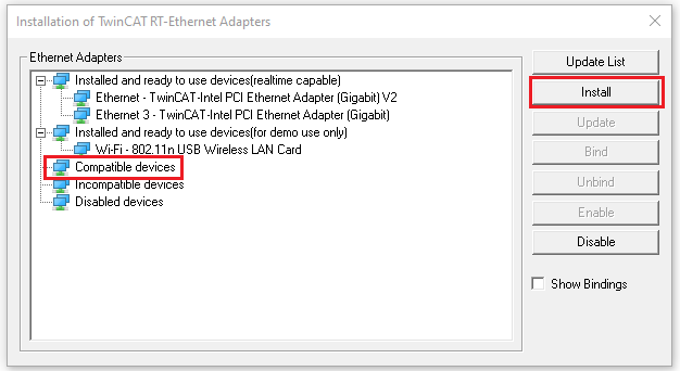
- The adapter must appear under the
- Close the previous window.
- Click
Search....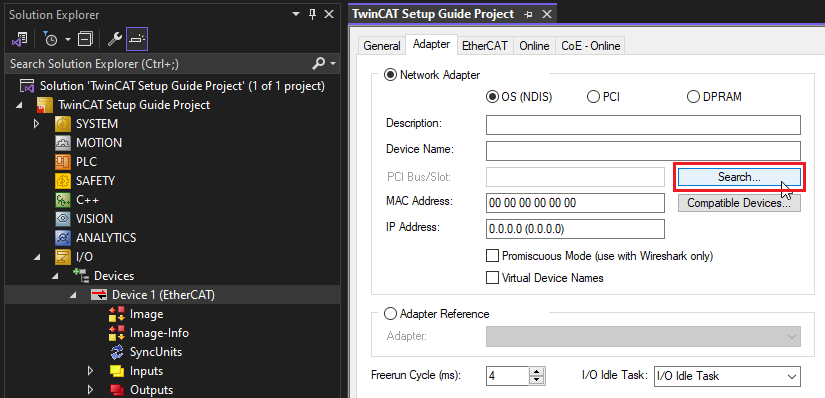
- Select your desired network adapter and click
OK.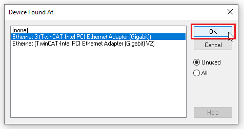
Your network adapter is now properly configured to function as an EtherCAT master with TwinCAT.
- Information about the adapter can be seen in the TwinCAT interface.
Configuring System Base Time
The system base time represents the minimum possible TwinCAT cycle time on each CPU core. This time can be configured independently for different cores. Specific TwinCAT tasks can also be allocated to certain cores. For performance reasons it may be beneficial to put certain fast processes onto one specific core.
To adjust the system base time:
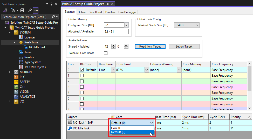
- Expand the
SYSTEMtree, and double clickReal-Time.- This will open the list of cores and tasks on the EtherCAT master.
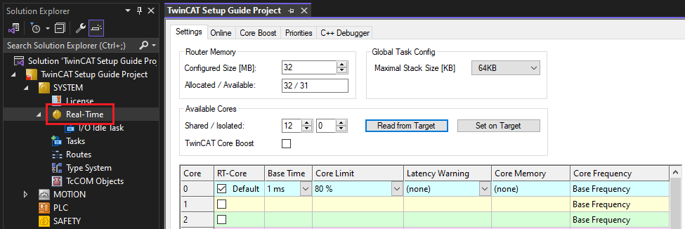
- This will open the list of cores and tasks on the EtherCAT master.
- Click
Read from Target.- This will list all the available cores on your machine.
- Select your desired base time for the given core.
- If needed, adjust the core for any TwinCAT tasks.
- This can be useful if one core has a high CPU usage.
- This can be useful if one core has a high CPU usage.
Configuring Process Data
The default process data configuration on the E-MCC will usually suffice for basic motion purposes. However, in certain cases it may be desirable to modify the process data. One particular example is for non-encoder devices; it is desirable to remove the Position Actual Value and Following Error Actual Value objects because these values are invalid without a position feedback sensor.
There are three methods to adjust process data:
- Changing Modules - Simple for basic changes
- Adjusting Modules Process Data - Recommended for axis specific changes
- Manually Adjusting Process Data - For other changes
Note: Any time the TwinCAT process data has changed, Activate Configuration needs to be clicked to apply the new configuration to your physical EtherCAT network.
Changing Modules
Modules/Slots provide convenient presets of process data which can be assigned individually to an E-MCC axis.
To modify the module configuration:
- Select the E-MCC in the
I/Otree, then open theSlotstab.- This allows viewing the existing module configuration for each axis, and list of available modules.
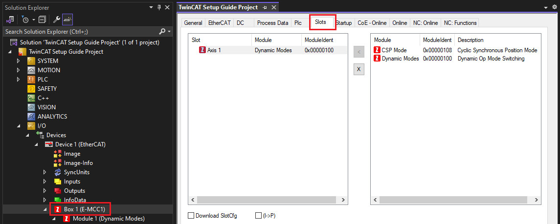
- This allows viewing the existing module configuration for each axis, and list of available modules.
- To un-assign a module, select it and click the
Xbutton.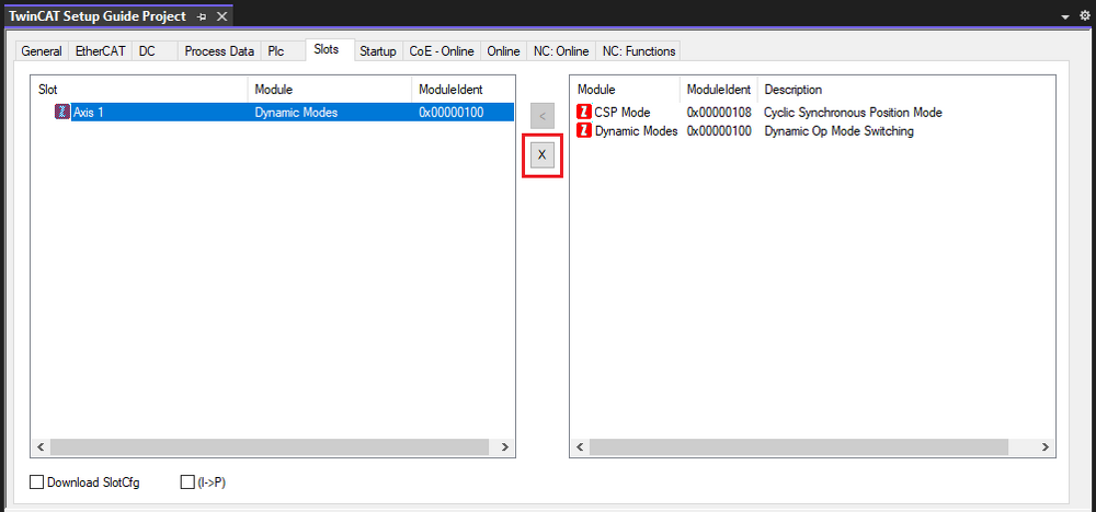
- To assign a new module, select it and click the
<button.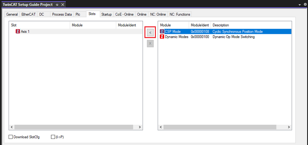
- The process data objects for the assigned module can be viewed in the
I/Otree.- Note: Process data for a specific module always appears under a separate sub-item (Module 1) beneath the E-MCC.
- Note: Process data for a specific module always appears under a separate sub-item (Module 1) beneath the E-MCC.
Adjusting Modules Process Data
If you desire more process data configurability than what the default modules provide, it’s possible to manually edit the process data assigned by the module.
To manually edit the module’s process data:
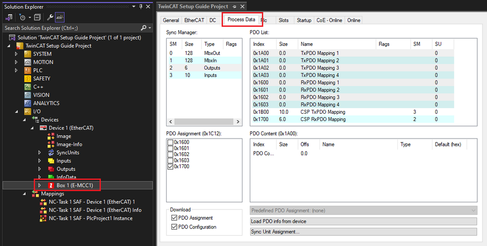
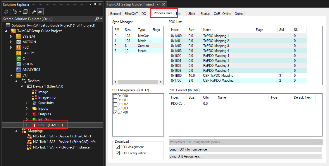
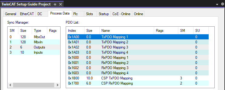
- Select the E-MCC in the
I/Otree, then open theProcess Datatab.- This tab can be used to manually edit all process data on the E-MCC.
- This tab can be used to manually edit all process data on the E-MCC.
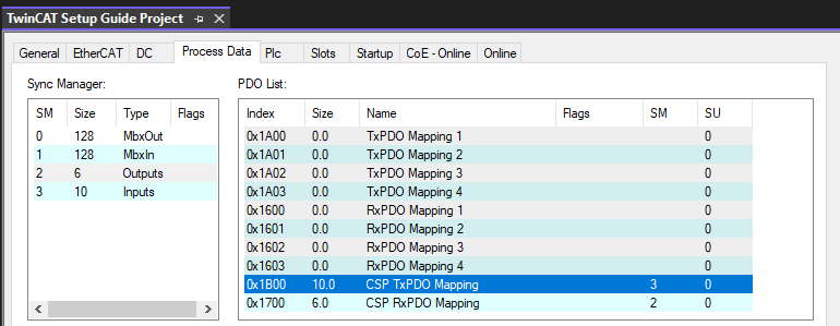
- Select the process data (PDO) mapping for the module you want to edit.
- Module input mappings start at index 0x1B00 + 0x010 per axis.
- Module output mappings start at index 0x1700 + 0x010 per axis.
- The contents of the PDO mapping can be seen in the
PDO Contentlist below. To remove an object, right click on it and selectDelete. ClickYesto delete the item.- In this example, we’ll remove Position Actual Value (object 0x6064).
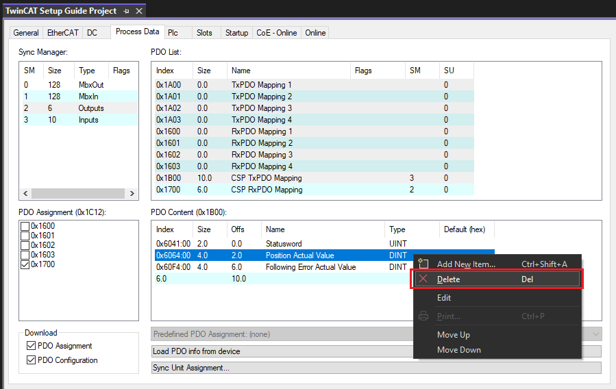
- In this example, we’ll remove Position Actual Value (object 0x6064).
- In the
I/Otree, confirm that your process data has been modified correctly.- Tip: If you’ve made a mistake, un-assigning and re-assigning the module will reset any module specific PDO mappings to the module’s default objects.
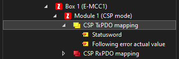
- Tip: If you’ve made a mistake, un-assigning and re-assigning the module will reset any module specific PDO mappings to the module’s default objects.
Manually Adjusting Process Data
In addition to modules, the E-MCC has eight PDO mappings intended for general purpose use:
- Four input mappings (0x1A00 - 0x1A03)
- Four output mappings (0x1600 - 0x1603)
By default these mappings are unassigned. However, if you want to transfer general purpose process data it is recommended to use these mappings.
To use these general purpose PDO mappings:
- Select the E-MCC in the
I/Otree, then open theProcess Datatab.- This tab can be used to manually edit all process data on the E-MCC.
- This tab can be used to manually edit all process data on the E-MCC.
- Select the PDO mapping you want to edit.
- We’ll edit TxPDO Mapping 1 (0x1A00) in this example.
- We’ll edit TxPDO Mapping 1 (0x1A00) in this example.
- With the mapping selected, right click on the empty
PDO Contentline and clickAdd New Item....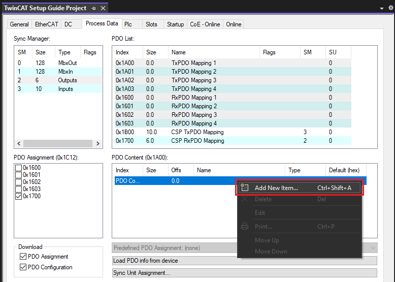
- Select the object you want to add to the PDO mapping and click
OK.- Note: Only certain objects can be PDO mapped. Available objects will show up on the list.
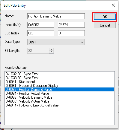
- Note: Only certain objects can be PDO mapped. Available objects will show up on the list.
- To assign (activate) the PDO mapping, click
Inputsand select the checkbox next to the corresponding mapping (0x1A00 for this example).- Note: If you’re working with RxPDO mappings, select
Outputsinstead ofInputs.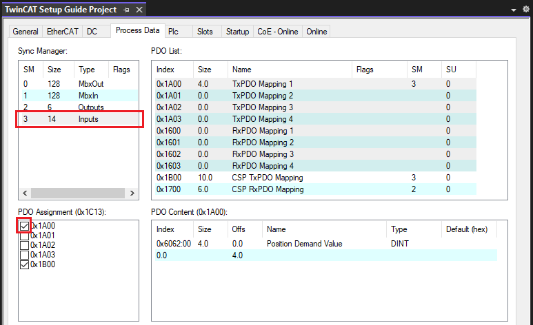
- Note: If you’re working with RxPDO mappings, select
- In the
I/Otree, confirm that your changes have been applied.- Note: Because 0x1A00 is a general purpose mapping, it is displayed under the E-MCC instead of Module 1.
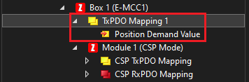
- Note: Because 0x1A00 is a general purpose mapping, it is displayed under the E-MCC instead of Module 1.
This procedure is the same for input and output (Tx and Rx) PDO mappings. PDO mappings can also be unassigned in a similar manner.
Homing an Axis
TwinCAT does not include default homing support for third party drives like Zaber’s E-MCC. The E-MCC uses CiA 402 Operation Mode 6 (HM mode) for homing, which is also known as drive based homing. There are two recommended methods to use drive based homing in TwinCAT:
Manual homing is convenient if you haven't setup a PLC project yet. For most use-cases, you'll want to perform homing in the PLC project.
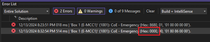
Note: An un-homed axis will transmit an emergency message with error code Hex: 8680 upon the ESM entering OP state. Once homing has completed, another emergency message with error code Hex: 0000 will be transmitted to indicate the warning has been cleared.
Homing Manually
To home an axis manually:
- Ensure TwinCAT is in Run Mode.
- Expand the
I/Otree to view the process data of your axis.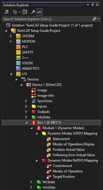
- Right click on
Modes of Operation. ClickOnline Force...and set the value to 6 (decimal).- This temporarily overrides the EtherCAT process data and forces the axis into homing mode (CiA 402 mode 6).
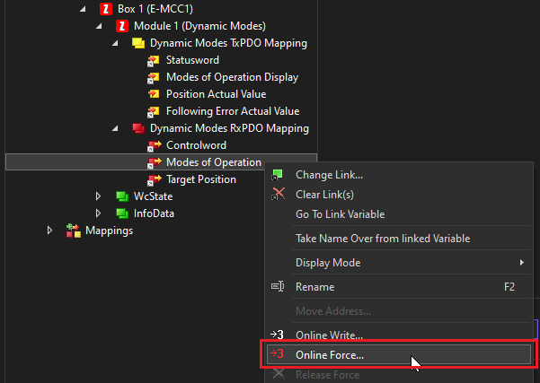
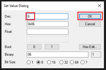
- This temporarily overrides the EtherCAT process data and forces the axis into homing mode (CiA 402 mode 6).
- Right click on
Controlwordand selectOnline Force.... Set the value to 15 (decimal).- This will enable the motor.
- Value 15 (decimal) raises the first 4 bits of object 0x6040 ControlWord, transitioning the CiA402 State Machine into Operation Enabled.
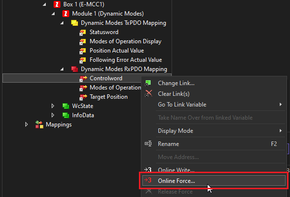
- Repeat the last step and Online Force the Controlword value to 31 (decimal).
- This will initiate the homing process.
- Value 31 (decimal) raises the first 5 bits of object 0x6040 ControlWord. A rising edge of bit 5 causes homing to initiate.
- Once homing is completed, you will see the error
Hex: 0000.- This indicates the previous error has been cleared (homing has completed).
- This indicates the previous error has been cleared (homing has completed).
- Right click on
Controlwordand selectRelease Force.- This returns control of the process data to the NC Axis.
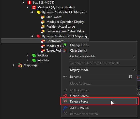
- This returns control of the process data to the NC Axis.
- Right click on
Modes of Operationand selectRelease Force.- This returns control of the process data to the NC Axis.
Homing From a PLC Project
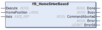
Zaber provides example code with a function block FB_HomeDriveBased to perform homing from a PLC project. This function block adheres to standard PLCopen programming conventions.
Download: Zaber TwinCAT Homing Example.zip
This code can be directly opened, run, and modified as a TwinCAT PLC project. However, for simple re-use it is recommended to save the PLC project as a TwinCAT library. See Library Creation for more details from Beckhoff.
To use the example code as a library:
- Download the project and open
Zaber TwinCAT Homing Example.sln. - Expand the
PLCtree. Right click onHomingExample Projectand selectSave as library and install....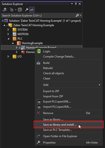
- Save the file
HomingExample.compiled-libraryto a folder of your choice.- Note: It is not required to keep this file. TwinCAT will automatically install it to your library repository folder (usually C:\ProgramData\Beckhoff\TwinCAT\PlcEngineering\Managed Libraries).
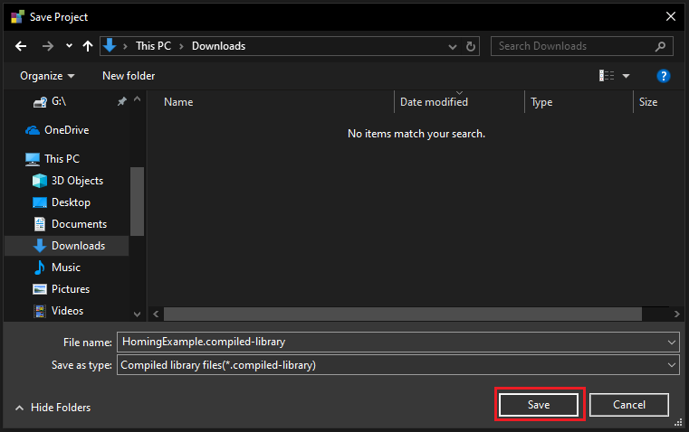
- Note: It is not required to keep this file. TwinCAT will automatically install it to your library repository folder (usually C:\ProgramData\Beckhoff\TwinCAT\PlcEngineering\Managed Libraries).
- Close the example project.
- Create a new TwinCAT XAE project, or open an existing project of your choice.
- If creating a new project, right click on
PLCand selectAdd New Item....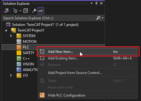
- Add a new
Standard PLC Projectwith the name of your choice.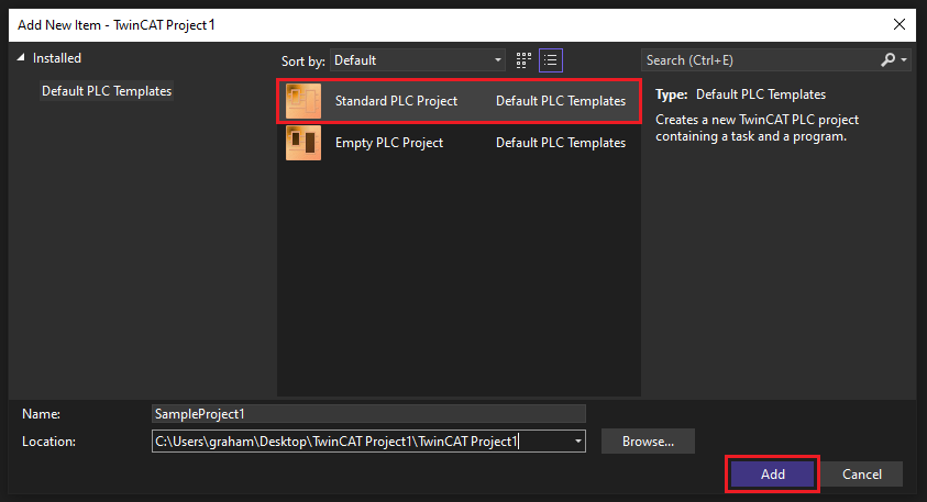
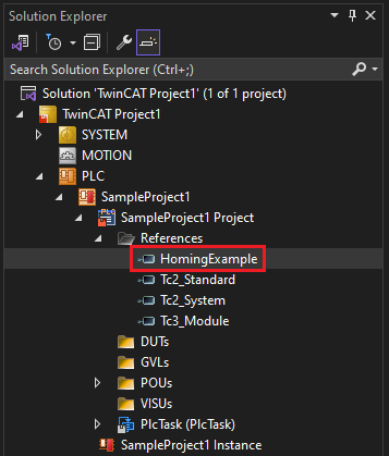
- Expand the PLC project. Right click on
Referencesand selectAdd library....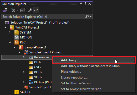
- Select
HomingExampleand clickOK.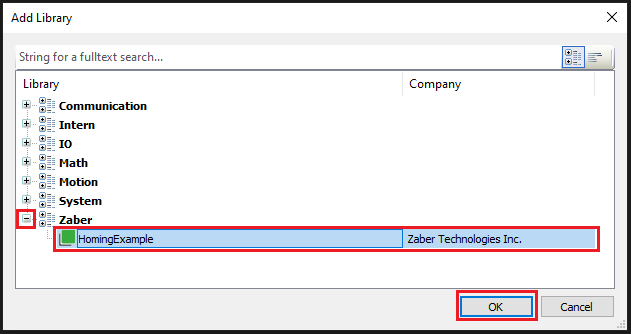
- The library should be added to your PLC project.
- The
FB_HomeDriveBasedfunction block is now ready for use in your PLC project. For more information, double click on the library and expand thePOUssection to view available function blocks in the library.- This includes documentation on the function block’s inputs and outputs.
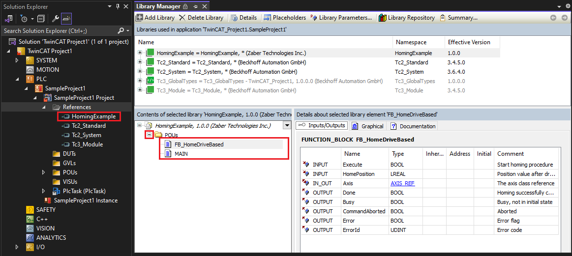
- This includes documentation on the function block’s inputs and outputs.