X-MCC Series
Multi-axis universal motor controllers
About This Series
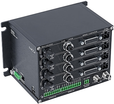
The X-MCC is Zaber’s full feature multi-axis universal drive controller and is available in 1, 2, 3, and 4 axis options. The universal drive is capable of controlling stepper motors, linear motors, and voice coil motors on any axis. Each axis may be equipped with its own encoder (digital or analog, single-ended or differential) and up to three limit sensors, including home and away.
When connected to the X-MCC, Zaber’s AutoDetect peripherals will be automatically identified and the axis will be configured with optimized drive settings for the specific device. No additional user input is needed.
The controller provides for 4 channels each of isolated digital inputs, isolated digital outputs, and non-isolated analog inputs. There is also a single analog output channel available.
An intuitive ASCII interface allows the user to easily communicate with the device using our free software, either Zaber Motion Library with APIs for several popular languages or Zaber Launcher. Third-party terminal programs that can communicate over a serial port can also be used.
The X-MCC uses lines, circles, arcs, and helices as geometric primitives while obeying velocity, acceleration, and timing constraints. The result is an easy-to-use set of 2D commands and a seamless transition between lines and curves.
An E-Stop interface is available on the X-MCC series that will stop current flow to all motors. The E-Stop is implemented fully in hardware to guarantee torque is removed from all motors.
The X-MCC series is compatible with all of Zaber's existing X-Series products. When daisy-chained with several units, the X-MCC can also share a single power supply with multiple X-Series products.
Click here to see the list of devices the X-MCC can control.
- Universal drive with cycle-by-cycle current control and advanced motion algorithms.
- Run stepper motors, linear motors, and voice coil motors up to 6 Arms per phase.
- Four opto-isolated digital inputs.
- Four opto-isolated digital outputs.
- Four non-isolated analog inputs.
- LEDs indicate the status of the controller and each axis.
- Indexed knobs provide convenient manual control.
- Programmable triggers based on time, distance, settings or inputs for stand-alone operation.
- Multiple units can be daisy-chained and controlled via serial port. Power can also be shared in the chain.
- Multiple mounting options for attaching controller to panel, optical breadboard, or electronic cabinet.
- Integrated USB 2.0.
- E-Stop input allows the axes to be powered down in an emergency.
- Built-in and external regen resistors to handle extreme deceleration conditions.
- Ethernet communications (10/100 Mbit/s).
Easy Set-Up
For more details on daisy-chaining, read our technical article, "Daisy-chaining Data and Power to Reduce Cabling", or to determine which accessories you need for your system, try our Connection Guide Tool.
For additional information about setting up our devices, please visit our Support page, which includes our Getting Started Guide, Troubleshooting Guides, product user manuals, and other resources.