RSM-V1 Series User's Manual
Low vacuum light load rotary stages
Disclaimer
Zaber’s products are not intended for use in any critical medical, aviation, or military applications or situations where a product's use or failure could cause personal injury, death, or damage to property. Zaber disclaims any warranty of fitness for a particular purpose. The user of this product agrees to Zaber's general terms and conditions of sale.
Precautions
Zaber’s motion control devices are precision instruments and must be handled with care. In particular, moving parts must be treated with care. Avoid axial loads in excess of the rated thrust load, axial and radial impact, dust and other contaminants and damage to the leadscrew thread. These will reduce the performance of the device below stated specifications.
Overheating Precautions
The lifetime of the motor and stage will be prolonged by keeping the operating temperatures as low as possible. The motor housing temperature of Zaber's vacuum devices should never exceed 80°C as the longevity of the devices will be compromised.
Monitoring Temperature
There are a few ways to monitor temperature on Zaber devices:
- A and X Series devices have an integrated temperature sensor on their controllers. This may be polled in ASCII using the command driver.temperature Please see the Quick Command Reference section for more details.
- A K-type thermocouple or other temperature sensor may be mounted to the stage to monitor temperature in order to reduce the risk of overheating. The thermocouple should be attached to the device's motor housing. An example of a proper mounting location is shown below.
.jpg)
Duty Cycle and Run and Hold Currents
The default run currents on Zaber vacuum devices are set lower than their non-vacuum counterparts however under high duty cycles they may have to be further lowered. Combining low run and hold currents with a reduced duty cycle will often prevent overheating in all but the most extreme of cases.
It is good practice to reduce the hold current as much as is practical for vacuum devices. Positioners with an A pitch leadscrew often do not need a hold current at all to maintain their position. Reducing the hold current is an easy way to reduce the heat generated by your vacuum stage or actuator.
Please contact Zaber Technical Support to help select the optimal duty cycle and current settings for your positioner.
Vacuum Baking
Vacuum devices can be vacuum baked to reduce pump down time and outgassing. The procedure is to heat the device to its recommended bake-out temperature at a vacuum of less than 10^-3 Torr for a period of several hours. Allowable bake-out temperature for Zaber's vacuum devices is 80°C.
Do not exceed these temperatures as there are polymer based components in the stage and electrical components in the controller that can be permanently damaged or have their lifetimes significantly shortened by overheating.
Installation
The RSM-V stages are designed to be controlled with any of Zaber's X-Series or A-Series Stepper Motor Controllers. Zaber's controllers and peripherals are designed for ease of use when used together. Optimal settings for each peripheral (such as the default current, speed, acceleration, and limit settings) can be loaded by setting the peripheralid (T:66) on the controller. The peripheral ID is listed as the ID on the peripheral's label. A list of IDs is also available on the ID Mapping page. For more information on device operation, refer to the controller's user manual.
Physical Installation
RSM-V stages can be mounted flat (with a vertical axis of rotation) or on edge (having a horizontal axis of rotation) without additional hardware. M3 x 16mm fasteners (included) are recommended for mounting the device. The rotation platform should be rotated 45 degrees from the home position to allow access to mounting holes. Edge mounting requires removal of the two M3 set screws shown below. These keep debris out of the main gear cavity when edge mounting is not needed.
Alignment
The RSM-V has several features to help align the axis of rotation.
A 4 mm bore through the centre of the device is concentric with the rotation axis and will fit tightly around a locating 4 mm diameter dowel pin inserted from either the top or the bottom of the device.
Four 5.5 mm diameter feet on the base of the device are intended to interlock with compatible Zaber devices and locate the rotation axis. These include AP135-V and GSM-V goniometer products. The RSM-V top is also compatible with these alignment bosses and can be used to align AP146-V, AB147-V, and GSM-V goniometers on the RSM-V stage top.
Three reference sides are intended for edge-mounting alignment. The AP146-V accessory is designed specifically to align with the edge features on the RSM-V stage.
Vacuum Device Mounting Considerations
If possible, vacuum positioners should be mounted to a thermally conductive surface to aid in head dissipation. Preferably, there should be a conductive heat path from the positioner through to the outside of the chamber. If this is not possible, the device should be mounted to a large conductive surface within the chamber. This will help cooling by increasing the rate of radiative heat transfer.
Wiring/Feed-throughs
V1 and V2 vacuum devices are supplied with non-vacuum D-sub15 connectors for ease of testing. The wires must be cut and connected (crimped, screwed, or soldered) to a vacuum feed-through before the device can be operated inside a vacuum chamber. The cut off cable end can be wired to the air-side connector of a vacuum electrical feedthrough to connect directly with a Zaber controller outside of the vacuum chamber.
For the RSM-V the motor wires are 26 AWG and the hall sensor wires are 28 AWG.
Operation
This unit is designed to be controlled with any of Zaber's X-Series or A-Series Stepper Motor Controllers. Zaber's controllers and peripherals are designed for ease of use when used together. Optimal settings for each peripheral (such as the default current, speed, acceleration, and limit settings) can be loaded by setting the peripheralid (T:66) on the controller. The peripheral ID is listed as the ID on the peripheral's label. A list of IDs is also available on the ID Mapping page. For more information on device operation, refer to the controller's user manual.
Pinout for D-sub 15 Connectors (A-series and X-Series controllers and peripherals)
| A- or X-series controller (female) | 
|
|---|---|
| T3 Peripheral (male) | 
|
| T4 Peripheral (male) | 
|
| Pin # | Function |
|---|---|
| 1 | +5V |
| 2 | Encoder Error **** |
| 3 | reserved |
| 4 | Away Sensor *** |
| 5 | Home Sensor |
| 6 | Ground |
| 7 | Motor B1 |
| 8 | Motor A1 |
| 9 | +5V * |
| 10 | Encoder A * |
| 11 | Encoder B * |
| 12 | Encoder Index ** |
| 13 | Ground * |
| 14 | Motor B2 |
| 15 | Motor A2 |
* encoder embedded peripherals only
** devices with encoders with index only
*** devices with away sensors only
**** devices with linear or direct-reading encoders only
Motor
The RSM-V stage uses a size 08 stepper motor.
- 0.8 A / Phase
- 3.5 mH / phase
- A1 = Red
- A2 = Blue
- B1 = Black
- B2 = Green
Alternate Controllers
The device may be controlled by any 2-phase stepper motor controller with home sensor input. Warning: Operating the unit without correctly wiring up the home sensor can cause permanent damage to the unit. We do not recommend using your own controller unless you are familiar with how to control a stepper motor with a hall sensor limit switch. The following information is provided for reference only. Damage to the actuator or hall sensor due to incorrect wiring is not covered by warranty.
Home Sensor Wiring
A Hall effect sensor is mounted in the device for use as a home sensor. It is part number A1122LUA-T made by Allegro. Click here for data sheet. Your controller should be configured so the stage stops immediately (little deceleration) when the home sensor is triggered.
As of May 2026, the wiring colour for hall sensors in vacuum products has changed. Some devices shipped after this date may still have Legacy colours as stock is used up.

The Hall sensor has an open-collector output. The default output is high impedance when the Hall sensor is not active. When the sensor detects a magnet, the Hall sensor pulls the output low to ground.

If you are not using a Zaber controller, ensure that your controller has a pull-up resistor on the output line of the Hall sensor as shown in the diagram. The bypass capacitor is optional, but may help to eliminate false triggering in noisy environments. The typical value for the pull-up resistor (RLOAD) is 10k and for the bypass capacitor is 0.1uF to 1uF. The larger the capacitance, the better the noise filtering but the slower the response time.
Warranty and Repair
For Zaber's policies on warranty and repair, please refer to the Ordering Policies.
Standard products
Standard products are any part numbers that do not contain the suffix ENG followed by a 4 digit number. Most, but not all, standard products are listed for sale on our website. All standard Zaber products are backed by a one-month satisfaction guarantee. If you are not satisfied with your purchase, we will refund your payment minus any shipping charges. Goods must be in brand new saleable condition with no marks. Zaber products are guaranteed for one year. During this period Zaber will repair any products with faults due to manufacturing defects, free of charge.
Custom products
Custom products are any part numbers containing the suffix ENG followed by a 4 digit number. Each of these products has been designed for a custom application for a particular customer. Custom products are guaranteed for one year, unless explicitly stated otherwise. During this period Zaber will repair any products with faults due to manufacturing defects, free of charge.
How to return products
Customers with devices in need of return or repair should contact Zaber to obtain an RMA form which must be filled out and sent back to us to receive an RMA number. The RMA form contains instructions for packing and returning the device. The specified RMA number must be included on the shipment to ensure timely processing.
Email Updates
If you would like to receive our periodic email newsletter including product updates and promotions.
Contact Information
Contact Zaber Technologies Inc by any of the following methods:
| Phone | 1-604-569-3780 (direct) 1-888-276-8033 (toll free in North America) |
|---|---|
| Fax | 1-604-648-8033 |
| #2 - 605 West Kent Ave. N., Vancouver, British Columbia, Canada, V6P 6T7 | |
| Web | www.zaber.com |
| Please visit our website for up to date email contact information. |
The original instructions for this product are available at https://www.zaber.com/manuals/RSM-V1.
Appendix A: Default Settings
Please see the Zaber Support Page for default settings for this device.
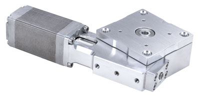
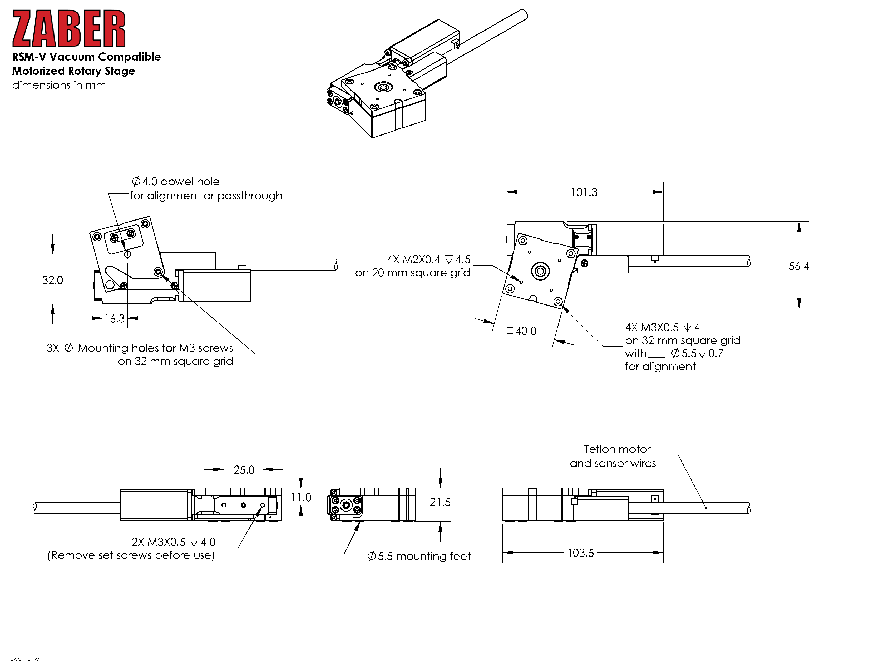
Product Drawing
Specifications
| Specification | Value | Alternate Unit |
|---|---|---|
| Microstep Size (Default Resolution) | 0.00046875° | 8.181 µrad |
| Built-in Controller | No | |
| Recommended Controller | MCC (48 V) Recommended | |
| AutoDetect | No | |
| Range | 360° | |
| Accuracy (unidirectional) | 0.14° | 2.443000 mrad |
| Repeatability | < 0.02° | < 0.349 mrad |
| Backlash | < 0.04° | < 0.698 mrad |
| Maximum Speed | 120°/s | 20 rpm |
| Minimum Speed | 0.000286°/s | 4.992 µrad/s |
| Speed Resolution | 0.000286°/s | 4.992 µrad/s |
| Encoder Type | None | |
| Maximum Continuous Torque | 0.2 N⋅m | 0.148 lb⋅ft |
| Maximum Centered Load | 50 N | 11.2 lb |
| Maximum Moment (Tilt) | 30 N⋅cm | 42.5 oz⋅in |
| Stage Top Dimension | 40 mm | 1.575" |
| Radial Error Motion | +/- 10 µm | +/- 0.000394" |
| Axial Error Motion | < 4 µm | < 0.000157" |
| Tilt Error Motion | +/- 0.011° | +/- 191.99 µrad |
| Bearing Plane Offset | 11 mm | 0.433" |
| Angular Motion Per Motor Rev | 6° | |
| Motor Steps Per Rev | 200 | |
| Motor Type | Stepper (2 phase) | |
| Motor Winding Inductance | 3.5 mH/phase | |
| Motor Connection | Teflon flying leads with D-sub15 connector | |
| Default Resolution | 1/64 of a step | |
| Motor Frame Size | NEMA 08 | |
| Mechanical Drive System | Precision Worm Gear | |
| Limit or Home Sensing | Magnetic home sensor | |
| Manual Control | No | |
| Mounting Interface | M2 and M3 mounting holes | |
| Operating Temperature Range | 0-50 °C | |
| CE Compliant | Yes | |
| Vacuum Compatible | Low vacuum (10-3 Torr) | |
| Weight | 0.300 kg | 0.661 lb |
Charts and Notes
Product Change Notices
Click here to view the current product change notices and subscribe to future change notifications.