NA Series (No Auto Detect) User's Manual
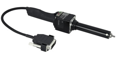
Electric linear actuators
Disclaimer
Zaber’s products are not intended for use in any critical medical, aviation, or military applications or situations where a product's use or failure could cause personal injury, death, or damage to property. Zaber disclaims any warranty of fitness for a particular purpose. The user of this product agrees to Zaber's general terms and conditions of sale.
Precautions
Zaber’s motion control devices are precision instruments and must be handled with care. In particular, moving parts must be treated with care. Avoid axial loads in excess of the rated thrust load, axial and radial impact, dust and other contaminants and damage to the leadscrew thread. These will reduce the performance of the device below stated specifications.
Installation
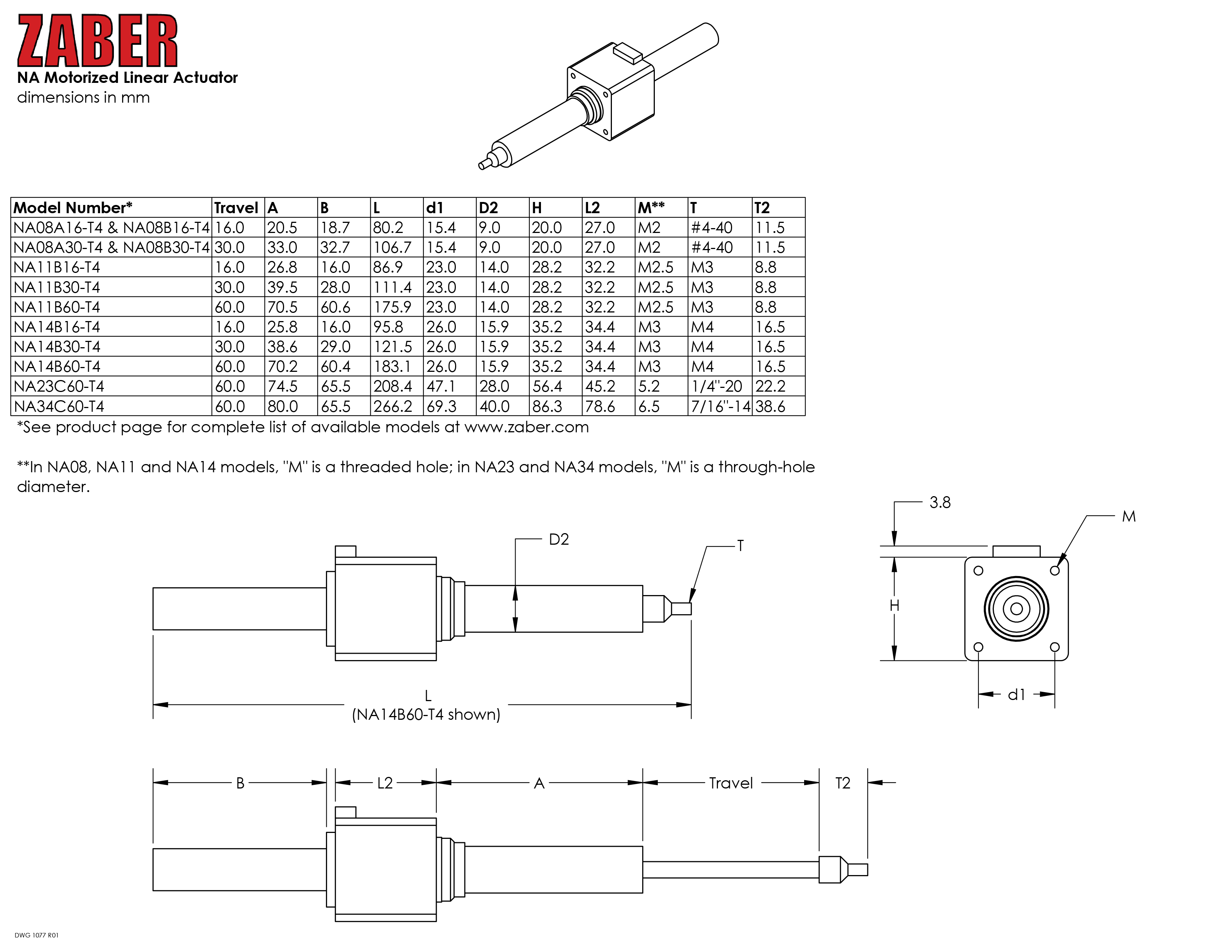
You can mount the NA actuators by the cylindrical mounting shank or by the four mounting holes on the square body section. See the NA web page for dimensions, resolution and other details.
Operation
This unit is designed to be controlled with any of Zaber's X-Series or A-Series Stepper Motor Controllers. Units produced before July 2012 with the round Minidin connectors are designed to be controlled with the older T-MCA series chopper drive controllers. Zaber's controllers and peripherals are designed for ease of use when used together. Optimal settings for each peripheral (such as the default current, speed, acceleration, and limit settings) can be loaded by setting the peripheralid (T:66) on the controller. The peripheral ID is listed as the ID on the peripheral's label. A list of IDs is also available on the ID Mapping page. For more information on device operation, refer to the controller's user manual.
Pinout for D-sub 15 Connectors (A-series and X-Series controllers and peripherals)
| A- or X-series controller (female) | 
|
|---|---|
| T3 Peripheral (male) | 
|
| T4 Peripheral (male) | 
|
| Pin # | Function |
|---|---|
| 1 | +5V |
| 2 | Encoder Error **** |
| 3 | reserved |
| 4 | Away Sensor *** |
| 5 | Home Sensor |
| 6 | Ground |
| 7 | Motor B1 |
| 8 | Motor A1 |
| 9 | +5V * |
| 10 | Encoder A * |
| 11 | Encoder B * |
| 12 | Encoder Index ** |
| 13 | Ground * |
| 14 | Motor B2 |
| 15 | Motor A2 |
* encoder embedded peripherals only
** devices with encoders with index only
*** devices with away sensors only
**** devices with linear or direct-reading encoders only
Pin-Out for Minidin 8 (T-MCA connector and CDC6 cable to Peripheral)
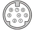
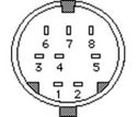
| Pin # | Function |
|---|---|
| 1 | Motor A1 |
| 2 | Motor A2 |
| 3 | Motor B1 |
| 4 | Not Connected |
| 5 | Motor B2 |
| 6 | +5V |
| 7 | Home Signal |
| 8 | Ground |
Alternate Controllers
The device may be controlled by any 2-phase stepper motor controller with home sensor input. Warning: Operating the unit without correctly wiring up the home sensor can cause permanent damage to the unit. We do not recommend using your own controller unless you are familiar with how to control a stepper motor with a hall sensor limit switch. The following information is provided for reference only. Damage to the actuator or hall sensor due to incorrect wiring is not covered by warranty.
Home Sensor Wiring
A Hall effect sensor is mounted in the device for use as a home sensor. It is part number A1122LUA-T made by Allegro. Click here for data sheet. Your controller should be configured so the stage stops immediately (little deceleration) when the home sensor is triggered.
- Wire colour code:
- 3.6-24 Vdc input - red
- Home signal - yellow
- Ground - black
The Hall sensor has an open-collector output. The default output is high impedance when the Hall sensor is not active. When the sensor detects a magnet, the Hall sensor pulls the output low to ground.

If you are not using a Zaber controller, ensure that your controller has a pull-up resistor on the output line of the Hall sensor as shown in the diagram. The bypass capacitor is optional, but may help to eliminate false triggering in noisy environments. The typical value for the pull-up resistor (RLOAD) is 10k and for the bypass capacitor is 0.1uF to 1uF. The larger the capacitance, the better the noise filtering but the slower the response time.
Warranty and Repair
For Zaber's policies on warranty and repair, please refer to the Ordering Policies.
Standard products
Standard products are any part numbers that do not contain the suffix ENG followed by a 4 digit number. Most, but not all, standard products are listed for sale on our website. All standard Zaber products are backed by a one-month satisfaction guarantee. If you are not satisfied with your purchase, we will refund your payment minus any shipping charges. Goods must be in brand new saleable condition with no marks. Zaber products are guaranteed for one year. During this period Zaber will repair any products with faults due to manufacturing defects, free of charge.
Custom products
Custom products are any part numbers containing the suffix ENG followed by a 4 digit number. Each of these products has been designed for a custom application for a particular customer. Custom products are guaranteed for one year, unless explicitly stated otherwise. During this period Zaber will repair any products with faults due to manufacturing defects, free of charge.
How to return products
Customers with devices in need of return or repair should contact Zaber to obtain an RMA form which must be filled out and sent back to us to receive an RMA number. The RMA form contains instructions for packing and returning the device. The specified RMA number must be included on the shipment to ensure timely processing.
Email Updates
If you would like to receive our periodic email newsletter including product updates and promotions.
Contact Information
Contact Zaber Technologies Inc by any of the following methods:
| Phone | 1-604-569-3780 (direct) 1-888-276-8033 (toll free in North America) |
|---|---|
| Fax | 1-604-648-8033 |
| #2 - 605 West Kent Ave. N., Vancouver, British Columbia, Canada, V6P 6T7 | |
| Web | www.zaber.com |
| Please visit our website for up to date email contact information. |
The original instructions for this product are available at https://www.zaber.com/manuals/NA.
Appendix A: Default Settings
Please see the Zaber Support Page for default settings for this device.
Product Drawing
Specifications
| Specification | Value | Alternate Unit |
|---|---|---|
| Built-in Controller | No | |
| Recommended Controller | Contact Us | |
| AutoDetect | No | |
| Encoder Type | None | |
| Motor Temperature Rise | 75 °C | |
| Motor Steps Per Rev | 200 | |
| Motor Type | Stepper (2 phase) | |
| Motor Connection | D-sub 15 | |
| Default Resolution | 1/64 of a step | |
| Mechanical Drive System | Precision lead screw | |
| Limit or Home Sensing | Magnetic home sensor | |
| Axes of Motion | 1 | |
| CE Compliant | Yes | |
| Vacuum Compatible | No |
Comparison
| Part Number | Microstep Size (Default Resolution) | Travel Range | Accuracy (unidirectional) | Repeatability |
|---|---|---|---|---|
| NA08A16-T4 | 0.047625 µm | 16 mm (0.630") | 20 µm (0.000787") | < 5 µm (< 0.000197") |
| NA08A30-T4 | 0.047625 µm | 30 mm (1.181") | 20 µm (0.000787") | < 5 µm (< 0.000197") |
| NA08B16-T4 | 0.09525 µm | 16 mm (0.630") | 20 µm (0.000787") | < 5 µm (< 0.000197") |
| NA08B30-T4 | 0.09525 µm | 30 mm (1.181") | 20 µm (0.000787") | < 5 µm (< 0.000197") |
| NA11B16-T4 | 0.09921875 µm | 16 mm (0.630") | 25 µm (0.000984") | < 5 µm (< 0.000197") |
| NA11B30-T4 | 0.09921875 µm | 30 mm (1.181") | 25 µm (0.000984") | < 5 µm (< 0.000197") |
| NA11B60-T4 | 0.09921875 µm | 60 mm (2.362") | 36 µm (0.001417") | < 5 µm (< 0.000197") |
| NA14B16-T4 | 0.09525 µm | 16 mm (0.630") | 25 µm (0.000984") | < 5 µm (< 0.000197") |
| NA14B30-T4 | 0.09525 µm | 30 mm (1.181") | 25 µm (0.000984") | < 5 µm (< 0.000197") |
| NA14B60-T4 | 0.09525 µm | 60 mm (2.362") | 36 µm (0.001417") | < 5 µm (< 0.000197") |
| NA23C60-T4 | 0.1984375 µm | 60 mm (2.362") | 36 µm (0.001417") | < 5 µm (< 0.000197") |
| NA34C60-T4 | 0.1984375 µm | 60 mm (2.362") | 45 µm (0.001772") | < 10 µm (< 0.000394") |
| Part Number | Backlash | Maximum Speed | Minimum Speed | Speed Resolution |
|---|---|---|---|---|
| NA08A16-T4 | < 15 µm (< 0.000591") | 26 mm/s (1.024"/s) | 0.000029 mm/s (0.000001"/s) | 0.000029 mm/s (0.000001"/s) |
| NA08A30-T4 | < 15 µm (< 0.000591") | 26 mm/s (1.024"/s) | 0.000029 mm/s (0.000001"/s) | 0.000029 mm/s (0.000001"/s) |
| NA08B16-T4 | < 15 µm (< 0.000591") | 52 mm/s (2.047"/s) | 0.000058 mm/s (0.000002"/s) | 0.000058 mm/s (0.000002"/s) |
| NA08B30-T4 | < 15 µm (< 0.000591") | 52 mm/s (2.047"/s) | 0.000058 mm/s (0.000002"/s) | 0.000058 mm/s (0.000002"/s) |
| NA11B16-T4 | < 18 µm (< 0.000709") | 52 mm/s (2.047"/s) | 0.000061 mm/s (0.000002"/s) | 0.000061 mm/s (0.000002"/s) |
| NA11B30-T4 | < 18 µm (< 0.000709") | 52 mm/s (2.047"/s) | 0.000061 mm/s (0.000002"/s) | 0.000061 mm/s (0.000002"/s) |
| NA11B60-T4 | < 18 µm (< 0.000709") | 52 mm/s (2.047"/s) | 0.000061 mm/s (0.000002"/s) | 0.000061 mm/s (0.000002"/s) |
| NA14B16-T4 | < 20 µm (< 0.000787") | 52 mm/s (2.047"/s) | 0.000058 mm/s (0.000002"/s) | 0.000058 mm/s (0.000002"/s) |
| NA14B30-T4 | < 20 µm (< 0.000787") | 52 mm/s (2.047"/s) | 0.000058 mm/s (0.000002"/s) | 0.000058 mm/s (0.000002"/s) |
| NA14B60-T4 | < 20 µm (< 0.000787") | 52 mm/s (2.047"/s) | 0.000058 mm/s (0.000002"/s) | 0.000058 mm/s (0.000002"/s) |
| NA23C60-T4 | < 30 µm (< 0.001181") | 80 mm/s (3.150"/s) | 0.000121 mm/s (0.000005"/s) | 0.000121 mm/s (0.000005"/s) |
| NA34C60-T4 | < 65 µm (< 0.002559") | 30 mm/s (1.181"/s) | 0.000121 mm/s (0.000005"/s) | 0.000121 mm/s (0.000005"/s) |
| Part Number | Peak Thrust | Maximum Continuous Thrust | Linear Motion Per Motor Rev | Motor Rated Current |
|---|---|---|---|---|
| NA08A16-T4 | 25 N (5.6 lb) | 19 N (4.3 lb) | 0.6096 mm (0.024") | 490 mA/phase |
| NA08A30-T4 | 25 N (5.6 lb) | 19 N (4.3 lb) | 0.6096 mm (0.024") | 490 mA/phase |
| NA08B16-T4 | 20 N (4.5 lb) | 19 N (4.3 lb) | 1.2192 mm (0.048") | 490 mA/phase |
| NA08B30-T4 | 20 N (4.5 lb) | 19 N (4.3 lb) | 1.2192 mm (0.048") | 490 mA/phase |
| NA11B16-T4 | 58 N (13.0 lb) | 58 N (13.0 lb) | 1.27 mm (0.050") | 1000 mA/phase |
| NA11B30-T4 | 58 N (13.0 lb) | 58 N (13.0 lb) | 1.27 mm (0.050") | 1000 mA/phase |
| NA11B60-T4 | 58 N (13.0 lb) | 58 N (13.0 lb) | 1.27 mm (0.050") | 1000 mA/phase |
| NA14B16-T4 | 180 N (40.4 lb) | 180 N (40.4 lb) | 1.2192 mm (0.048") | 570 mA/phase |
| NA14B30-T4 | 180 N (40.4 lb) | 180 N (40.4 lb) | 1.2192 mm (0.048") | 570 mA/phase |
| NA14B60-T4 | 180 N (40.4 lb) | 180 N (40.4 lb) | 1.2192 mm (0.048") | 570 mA/phase |
| NA23C60-T4 | 700 N (157.0 lb) | 700 N (157.0 lb) | 2.54 mm (0.100") | 1300 mA/phase |
| NA34C60-T4 | 1200 N (269.1 lb) | 1200 N (269.1 lb) | 2.54 mm (0.100") | 1300 mA/phase |
| Part Number | Motor Winding Resistance | Motor Winding Inductance | Motor Rated Power | Motor Frame Size |
|---|---|---|---|---|
| NA08A16-T4 | 5.1 ohms/phase | 1.5 mH/phase | 2.45 watts | 08 |
| NA08A30-T4 | 5.1 ohms/phase | 1.5 mH/phase | 2.45 watts | 08 |
| NA08B16-T4 | 5.1 ohms/phase | 1.5 mH/phase | 2.45 watts | 08 |
| NA08B30-T4 | 5.1 ohms/phase | 1.5 mH/phase | 2.45 watts | 08 |
| NA11B16-T4 | 2.1 ohms/phase | 1.5 mH/phase | 4.2 watts | 11 |
| NA11B30-T4 | 2.1 ohms/phase | 1.5 mH/phase | 4.2 watts | 11 |
| NA11B60-T4 | 2.1 ohms/phase | 1.5 mH/phase | 4.2 watts | 11 |
| NA14B16-T4 | 8.8 ohms/phase | 13 mH/phase | 5.7 watts | 14 |
| NA14B30-T4 | 8.8 ohms/phase | 13 mH/phase | 5.7 watts | 14 |
| NA14B60-T4 | 8.8 ohms/phase | 13 mH/phase | 5.7 watts | 14 |
| NA23C60-T4 | 3.85 ohms/phase | 10.5 mH/phase | 13 watts | 23 |
| NA34C60-T4 | 1.6 ohms/phase | 8.8 mH/phase | 31.2 watts | 34 |
| Part Number | Mounting Interface | Weight |
|---|---|---|
| NA08A16-T4 | 4 M2 tapped holes 15.4 mm apart or 9 mm dia smooth shank | 0.07 kg (0.154 lb) |
| NA08A30-T4 | 4 M2 tapped holes 15.4 mm apart or 9 mm dia smooth shank | 0.08 kg (0.176 lb) |
| NA08B16-T4 | 4 M2 tapped holes 15.4 mm apart or 9 mm dia smooth shank | 0.07 kg (0.154 lb) |
| NA08B30-T4 | 4 M2 tapped holes 15.4 mm apart or 9 mm dia smooth shank | 0.08 kg (0.176 lb) |
| NA11B16-T4 | 4 M2.5 tapped holes 23 mm apart or 14 mm smooth shank | 0.15 kg (0.331 lb) |
| NA11B30-T4 | 4 M2.5 tapped holes 23 mm apart or 14 mm smooth shank | 0.16 kg (0.353 lb) |
| NA11B60-T4 | 4 M2.5 tapped holes 23 mm apart or 14 mm smooth shank | 0.17 kg (0.375 lb) |
| NA14B16-T4 | 4 M3 tapped holes 26 mm apart or 15 mm smooth shank | 0.15 kg (0.331 lb) |
| NA14B30-T4 | 4 M3 tapped holes 26 mm apart or 15 mm smooth shank | 0.22 kg (0.485 lb) |
| NA14B60-T4 | 4 M3 tapped holes 26 mm apart or 15 mm smooth shank | 0.23 kg (0.507 lb) |
| NA23C60-T4 | 5.2 mm holes | 0.75 kg (1.653 lb) |
| NA34C60-T4 | 6.5 mm hole | 2.64 kg (5.820 lb) |
Charts and Notes
Product Change Notices
Click here to view the current product change notices and subscribe to future change notifications.