LRQ-XY-XYZ Series User's Manual
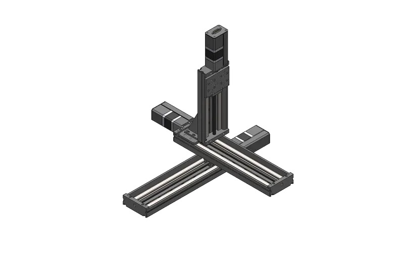
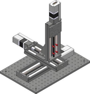
Multiple axis stages built with LRQs
Disclaimer
Zaber’s products are not intended for use in any critical medical, aviation, or military applications or situations where a product's use or failure could cause personal injury, death, or damage to property. Zaber disclaims any warranty of fitness for a particular purpose. The user of this product agrees to Zaber's general terms and conditions of sale.
Precautions
 Collision Hazard! Zaber XY XYZ stages contain motion products with significant thrust and load capacities. Take caution to prevent collisions with operators, work surfaces, and sensitive equipment.
Heavy! Completely assembled products, partial assemblies and some stages can be very heavy. Exercise caution when lifting/moving larger assemblies and products. Loosely fasten stage axes as soon as they are placed during assembly, to prevent tipping and falling hazards.
 Important: XY XYZ products must be properly assembled and aligned to function optimally. Follow assembly instructions closely and contact Zaber Customer Support for help at any time, if needed.
Product Overview
| X-Axis | Y-Axis | Z-Axis (Optional) |
 |
 |

|
Cable Lengths
| Cable Type | Short Cable | Long Cable |
|---|---|---|
| Data Cable | X-DC02 (0.6 m) | X-DC06 (2.0 m) |
| Motor Cable | MC10(T3) (1.5 m) | MC10(T3)L300 (3.0 m) |
If using X-series devices with an integrated controller, refer to the data cable equations below:
| Connection | Equation |
|---|---|
| X-Y Connection | If X-travel + Y-travel/2 > 300, use the 2 m cable. Otherwise use the 0.6 m cable.
|
| Y-Z Connection | If Y-travel + Z-travel > 400, use the 2 m cable. Otherwise use the 0.6 m cable.
|
If using an X-MCC coordinated motion controller, refer to the motor cable equations below:
| Axis | Equation |
|---|---|
| X-axis | Use 1.5 m cable. |
| Y-axis | If X-travel + (Y-travel/2) >= 1000, use the 3.0 m cable. Otherwise use the 1.5 m cable.
|
| Z-axis | If X-travel + (Y-travel/2) + Z-travel >= 1000, use the 3.0 m cable. Otherwise use the 1.5m cable.
|
XY XYZ Stage Assembly and Setup
Zaber's XY XYZ stages require some assembly and set-up upon arrival. These XY XYZ stages can be disassembled, packed, and transported for use in new locations, or re-configured with new motion control axes to suit new applications. To set up your XY or XYZ stage, complete the following steps (where applicable).
Required Tools
- 5 mm hex key
- Machinist's square [SQ3] (Included)
Preparation
- Unpack the brackets, adaptor plates, and other hardware.
- Keep fasteners with their labelled bags to easily identify/locate the correct fastener for a step.
- Unpack the stage axes and identify the X-axis stage, Y-axis stage and the Z-axis stage if included. Refer to your purchase to determine which axis each stage belongs to.
- Typically the longest stage should be the X-axis. The X and Y axis will have the same pitch. The Z axis will generally have a fine pitch screw (A pitch) or a brake.
- Determine your mounting surface. The instructions provided assume a metric optical breadboard is used to mount the X-axis stage.
- Determine stage orientations and location of the X-MCC controller, if included. The controller is typically located near the motor cable connections of the X-axis (lowest stage). If the controller is required to be mounted at a significant distance from the stages, longer cables or cable extensions may be necessary. See MC10T3(Lxxx) for longer 15 pin female to 26 pin male cables or MC10(Lxxx) for 26 pin female to 26 pin male extensions cables here: Zaber Accessories.
- Note: 'xxx' denotes a length in cm
LRQ X-Axis Stage to Breadboard
Precautions
Heavy
Assembly
-
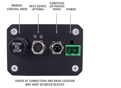
For the next steps, first connect the stage to power using the provided power supply. If using an X-MCC coordinated motion controller, connect the stage to the controller as well. Confirm that the manual control knob on the controller can be used to move the carriage around to provide access to the mounting slots beneath the carriage.
-

If your LRQ features a dust cover, it must be removed before mounting and reinstalled before the next axis is attached.
-
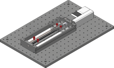
Loosely attach the X-axis stage on a breadboard or other mounting surface using the four provided stainless steel M6 screws and a 5 mm hex key. Move the carriage as necessary to access mounting slots. Where possible, space fasteners out equally and place fasteners at each end of travel.
-
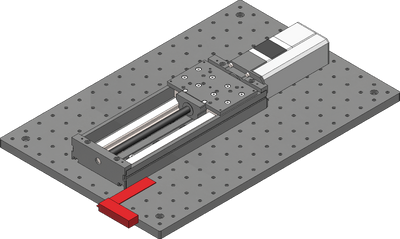
Using the included machinist's square, align the X-axis stage to an edge of the breadboard or other reference edge.
-
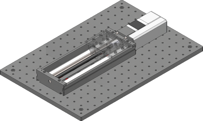
Firmly tighten down all fasteners mounting the X-axis stage.
-
If your LRQ features a dust cover, reinstall it before the next axis is attached.
LRQ Y-Axis Stage to X-Axis
Precautions
Important: Where possible, mount the Y-axis stage so that its travel is centered on the X-axis stage to reduce moment loads and off-axis motion errors.
Assembly
-
For the next steps, first connect the stage to power using the provided power supply. If using an X-MCC coordinated motion controller, connect the stage to the controller as well. Confirm that the manual control knob on the controller can be used to move the carriage around to provide access to the mounting slots beneath the carriage. Note: For the 25mm travel LRMs, the central pair of mounting slots is inaccessible.
-
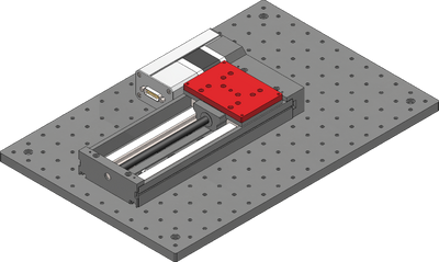
If your stages are in the parallel configuration instead of the in-line configuration, use the included AP165 adaptor plate to space out the upper stage. The parallel configuration with a dust cover does not require the adaptor plate.
-
If your LRQ features a dust cover, it must be removed before mounting and reinstalled before the next axis is attached.
-
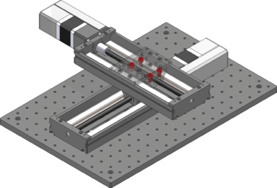
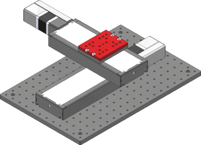
Loosely attach the Y-axis stage over the X-axis using the four provided stainless steel M6 screws and a 5 mm hex key. The Y-axis stage should be mounted so that the travel is centered on the X-axis. The system specifications and load ratings are provided assuming a centered mounting. If mounted elsewhere, the stiffness of the system will change, and in some cases loads may exceed the lower stage's carrying capacity.
-

Using the included machinist's square, align the Y-axis stage to the X-axis stage.
-
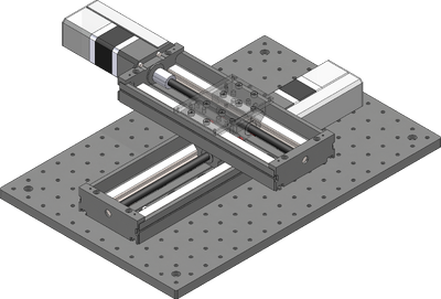
Firmly tighten down all fasteners mounting the Y-axis stage.
LRQ Z-Axis Stages to Y-Axis
This section is only applicable for XYZ stage products and can be ignored for XY stages.
Assembly
-
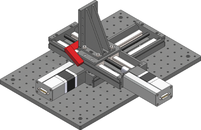
If your LRQ features a dust cover, use the provided AP163 adaptor plate before attaching the angle bracket
-
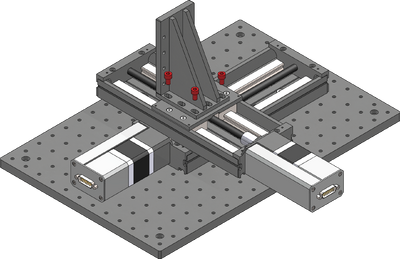
Loosely attach the provided AB151 Z-axis bracket over the Y-axis using the six provided M6 screws and a 5 mm hex key. The bracket can be mounted in the orientation shown, or rotated 90 degrees to overhang the Y-axis stage.
-
Using the included machinist's square, align the angle bracket to the Y-axis stage.
-
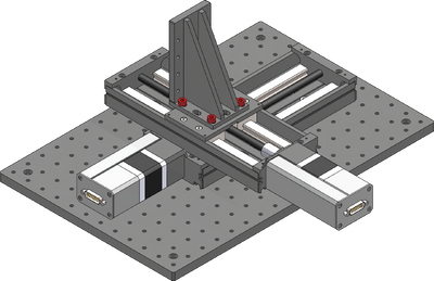
Firmly tighten down all fasteners mounting the angle bracket.
-
If your LRQ features a dust cover, it must be removed before mounting and reinstalled before the next axis is attached.
-
Attach the Z-axis stage using the provided M6 screws and a 5 mm hex key. Align with the machinist's square as necessary.
Cabling and Options
-
If using X-series Zaber stages with integrated controllers, then cabling is as simple as connecting the appropriate RS 232 data cables between each stage. These cables can be used to daisy chain both power and data, reducing clutter. For an XY stage, one data cable is needed, and for an XYZ stage, two data cables are needed. Refer to the cable table to determine which cables go where.
-
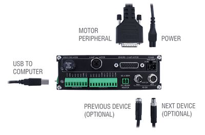
If using the X-MCC coordinated motion controller, then each stage needs to be directly connected to the controller with a motor cable. For an XY stage, two motor cables are needed, and for an XYZ stage, three motor cables are needed. Refer to the cable table to determine which cables go where.
-
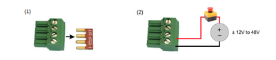
If using the X-MCC, the ES01 E-Stop accessory should also be installed at this point.
-
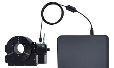
Connect the stage to the computer using the provided USB adaptor cable. This should be connected to the the X-axis stage (for X-series stages) or the X-MCC controller.
-
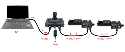
The optional joystick should be connected in-line between the computer and the X-axis stage (for X-series stages) or the X-MCC controller.
-
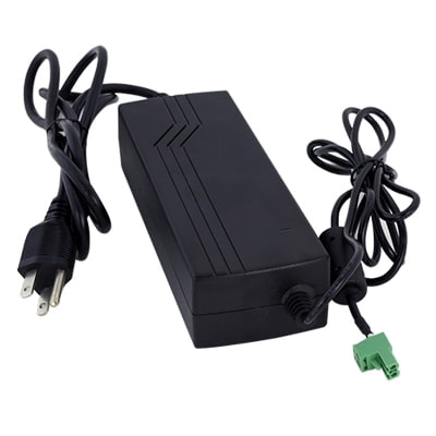
Power can be supplied to either the stages or the controller using the provided power supply brick. If multiple power supplies were provided, they should all be connected to the system to ensure sufficient current supply.
Dust Cover Removal and Installation
Use caution handling the shim as the edges are extremely sharp. For disassembly, simply remove the four screws securing the stainless steel dust cover shim and slide the shim out.
In most cases, the shim only needs to be lifted slightly to install the mounting screws and does not require full removal. Take care not to kink or bend the shim.
-

Move the stage at least 50mm away from one end of the LRQ base and feed the LRQ Dust Cover Shim in from one side. Use a business card as a ramp to help guide the shim over the first rise and under the second. Be careful not to kink the Dust Cover Shim or cut your fingers on the sharp metal!
-

Carefully feed the Dust Cover Shim through the stage top adapter, making sure that the shim doesn't rub directly on the aluminum of the Stage Top Adapter. Align the mounting holes at each end such that the Dust Cover Shim covers all of the magnet slots in the Sheet Metal Sides.
-

Take 2x M3x3 screws and thread them through the Dust Cover Shim and into the Dust Cover Shim Mount Away. Pull the shim as far as it can go towards the away end, and hand tighten the screws, ensuring that the Dust Cover Shim does not twist during tightening.
-

Take the remaining 2x M3x3 screws and thread them through the Dust Cover Shim and into the Dust Cover Shim Mount Home, leaving them loose. Push down on the Dust Cover Shim inside the Stage Top Adapter, and tighten the M3x3 screws.
-

When properly tensioned, the LRQ Dust Cover Shim should sit below the lid mounting ledge as indicated and should still have a slight bend. The LRQ Dust Cover Shim should be low enough that it does not contact the bottom of the LRQ Dust Cover Adapter Lid when installed, but it should not be so tight that it increases the drag of the stage.
-

Drive the LRQ stage back and forth through its full length a few times, and visually inspect that the Dust Cover Shim does not bulge anywhere during travel. If the shim bulges, loosen and then re-torque the M3x3 screw nearest the bulge in order to remove it. If loosening both screws on an end, you may need to push down on the shim inside the Stage Top Adapter again to add some tension. Repeat this process until the Dust Cover Shim stays flush with the Sheet Metal Sides through the full length of travel.
-

Take the LRQ Dust Cover Adapter Lid and place it in position on the Stage Top Adapter, ensuring that the countersink holes are on the top. Take the M2x4 screws and hand tighten them into the Stage Top Adapter.
Device Product Manuals
Zaber's XY XYZ stage products are combinations of several Zaber motion control devices. For device operation, maintenance procedures and troubleshooting, consult the detailed product manuals for these devices:
- X-LRQ-E Linear Stage
- Provides X,Y and optional Z axis linear motion in X-LRQ-E XY XYZ Stages.
- X-LRQ-EC Linear Stage
- Provides X,Y and optional Z axis linear motion in X-LRQ-EC XY XYZ Stages.
- X-LRQ-DE Linear Stage
- Provides X,Y and optional Z axis linear motion in X-LRQ-DE XY XYZ Stages.
- X-LRQ-DEC Linear Stage
- Provides X,Y and optional Z axis linear motion in X-LRQ-DEC XY XYZ Stages.
- LRQ-E Linear Stage
- Provides X,Y and optional Z axis linear motion in LRQ-E XY XYZ Stages.
- LRQ-EC Linear Stage
- Provides X,Y and optional Z axis linear motion in LRQ-EC XY XYZ Stages.
- LRQ-DE Linear Stage
- Provides X,Y and optional Z axis linear motion in LRQ-DE XY XYZ Stages.
- LRQ-DEC Linear Stage
- Provides X,Y and optional Z axis linear motion in LRQ-DEC XY XYZ Stages.
- X-MCC Universal Drive Controller
- These controllers are available with 1-4 axes. In an XY XYZ stage, a two or three axis controller is typically used to provide coordinated motion for when the path by the system taken matters. This controller may be daisy-chained with other Zaber controllers or motion devices with integrated control.
- X-JOY3 Joystick
- Optional programmable joystick with 8 buttons allows for direct interaction with the XY XYZ stage.
Warranty and Repair
For Zaber's policies on warranty and repair, please refer to the Ordering Policies.
Standard products
Standard products are any part numbers that do not contain the suffix ENG followed by a 4 digit number. Most, but not all, standard products are listed for sale on our website. All standard Zaber products are backed by a one-month satisfaction guarantee. If you are not satisfied with your purchase, we will refund your payment minus any shipping charges. Goods must be in brand new saleable condition with no marks. Zaber products are guaranteed for one year. During this period Zaber will repair any products with faults due to manufacturing defects, free of charge.
Custom products
Custom products are any part numbers containing the suffix ENG followed by a 4 digit number. Each of these products has been designed for a custom application for a particular customer. Custom products are guaranteed for one year, unless explicitly stated otherwise. During this period Zaber will repair any products with faults due to manufacturing defects, free of charge.
How to return products
Customers with devices in need of return or repair should contact Zaber to obtain an RMA form which must be filled out and sent back to us to receive an RMA number. The RMA form contains instructions for packing and returning the device. The specified RMA number must be included on the shipment to ensure timely processing.
Email Updates
If you would like to receive our periodic email newsletter including product updates and promotions.
Contact Information
Contact Zaber Technologies Inc by any of the following methods:
| Phone | 1-604-569-3780 (direct) 1-888-276-8033 (toll free in North America) |
|---|---|
| Fax | 1-604-648-8033 |
| #2 - 605 West Kent Ave. N., Vancouver, British Columbia, Canada, V6P 6T7 | |
| Web | www.zaber.com |
| Please visit our website for up to date email contact information. |
The original instructions for this product are available at https://www.zaber.com/manuals/LRQ-XY-XYZ.
Product Drawings
Specifications
| Specification | Value | Alternate Unit |
|---|---|---|
| CE Compliant | ||
| Weight |
This product uses the FreeRTOS kernel. FreeRTOS is © 2026 Amazon.com, Inc. or its affiliates and is governed by the following license:
All rights reserved.
Permission is hereby granted, free of charge, to any person obtaining a copy of this software and associated documentation files (the "Software"), to deal in the Software without restriction, including without limitation the rights to use, copy, modify, merge, publish, distribute, sublicense, and/or sell copies of the Software, and to permit persons to whom the Software is furnished to do so, subject to the following conditions:
The above copyright notice and this permission notice shall be included in all copies or substantial portions of the Software.
THE SOFTWARE IS PROVIDED "AS IS", WITHOUT WARRANTY OF ANY KIND, EXPRESS OR IMPLIED, INCLUDING BUT NOT LIMITED TO THE WARRANTIES OF MERCHANTABILITY, FITNESS FOR A PARTICULAR PURPOSE AND NONINFRINGEMENT.
IN NO EVENT SHALL THE AUTHORS OR COPYRIGHT HOLDERS BE LIABLE FOR ANY CLAIM, DAMAGES OR OTHER LIABILITY, WHETHER IN AN ACTION OF CONTRACT, TORT OR OTHERWISE, ARISING FROM, OUT OF OR IN CONNECTION WITH THE SOFTWARE OR THE USE OR OTHER DEALINGS IN THE SOFTWARE.
This product uses the LZ4 compression library. LZ4 is © 2011–2016 Yann Collet and is governed by the following license:
All rights reserved.
Redistribution and use in source and binary forms, with or without modification, are permitted provided that the following conditions are met:
- Redistributions of source code must retain the above copyright notice, this list of conditions and the following disclaimer.
- Redistributions in binary form must reproduce the above copyright notice, this list of conditions and the following disclaimer in the documentation and/or other materials provided with the distribution.
THIS SOFTWARE IS PROVIDED BY THE COPYRIGHT HOLDERS AND CONTRIBUTORS "AS IS" AND ANY EXPRESS OR IMPLIED WARRANTIES, INCLUDING, BUT NOT LIMITED TO, THE IMPLIED WARRANTIES OF MERCHANTABILITY AND FITNESS FOR A PARTICULAR PURPOSE ARE DISCLAIMED. IN NO EVENT SHALL THE COPYRIGHT HOLDER OR CONTRIBUTORS BE LIABLE FOR ANY DIRECT, INDIRECT, INCIDENTAL, SPECIAL, EXEMPLARY, OR CONSEQUENTIAL DAMAGES (INCLUDING, BUT NOT LIMITED TO, PROCUREMENT OF SUBSTITUTE GOODS OR SERVICES; LOSS OF USE, DATA, OR PROFITS; OR BUSINESS INTERRUPTION) HOWEVER CAUSED AND ON ANY THEORY OF LIABILITY, WHETHER IN CONTRACT, STRICT LIABILITY, OR TORT (INCLUDING NEGLIGENCE OR OTHERWISE) ARISING IN ANY WAY OUT OF THE USE OF THIS SOFTWARE, EVEN IF ADVISED OF THE POSSIBILITY OF SUCH DAMAGE.