Simplifying Imaging for Microfluidics
By Stefan Martin, Mechanical Engineering Team & Mike Fussell, Marketing Team
Published on May 24, 2022
Imaging serves several critical functions when testing and operating microfluidic devices. It can be used to verify the correct operation of the device during the design and testing phase and to perform in-process cytometry or reaction analysis. High speed imaging can confirm the rate of fluid delivery, the performance of elements such as droplet generators and mixers, and the sequence of operations performed on droplets. Imaging can also be used to readout experimental results by detection of a fluorescent signal or a change in absorbance or transmission of specific wavelengths of light. The small size and high speed of droplets moving through microfluidic devices creates a uniquely challenging set of requirements for an imaging system.
Nucleus® Automated Microscopy Platform Provides a Flexible “All In One” Solution
Successful acquisition of accurate and actionable images of microfluidic devices in operation requires precise coordination of the positioning, focus, and illumination of the microfluidic chip. The Nucleus automated microscopy platform provides a complete set of interchangeable hardware modules and software tools for building your bespoke inverted or upright standalone microscope. It is an extremely cost effective all-in-one solution for imaging microfluidic chips. They eliminate the need to source, install, and configure individual illumination, stage, motor controllers, each with their own control protocol and interface software. Instead, you use an online configurator guiding you to combine all of these systems into a single pre-assembled package (Fig. 1). A common communication protocol, interface software and API greatly simplifies both manual and automated image acquisition.
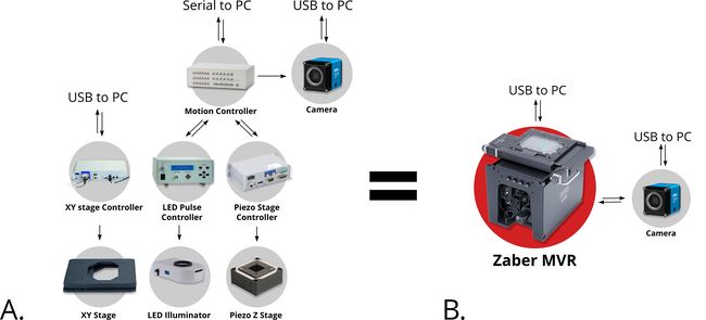
Figure 1. Compared to standard systems built from parts from many different suppliers (A), the Nucleus microscopy platform allows you to combine many discrete components into a single compact instrument (B). An open and modular system architecture and common control protocol provide both a high degree of configurability and simplicity of operation.
High-speed Microscopy for Droplet Microfluidics
Validating the function of droplet splitters, gates, and sorting within a microfluidic chip is a challenging task when designing a system capable of producing thousands of droplets per second. While a high-speed microscope camera is often the simplest solution, the cost of the camera and computer hardware which can handle the resulting extreme data rates may strain the budgets of many startups and research labs. Fortunately, there are alternative techniques which employ lower speed cameras to deliver accurate and actionable images without the high costs associated with high-speed imaging.
Stroboscopic Imaging
Figure 2. Stroboscopic image of droplets. The diagonally skewed shape of the droplets is due to rolling shutter distortion.
By using strobed illumination synchronized with the camera trigger it is possible to obtain sharp images of droplets in motion. When coupled with a droplet sync signal (laser PIV or similar), this can create animations of droplet passages at a greatly reduced cost as compared to high-speed camera set ups. With sufficiently stable flow conditions, it may be possible to remove this synchronization altogether and drive the system with an open loop control by sweeping the strobe frequency until the images are sharp. The skew distortion in moving droplets in the image above (Fig. 2) is due to the use of a camera with a rolling shutter CMOS image sensor. A camera with a global shutter CMOS image sensor is recommended for this method as it will capture more accurate images free of rolling shutter distortion (Fig. 4).
Moving Shot Imaging
Precision XY scanning stages make it possible to easily implement a “moving shot” imaging strategy. This method freezes the droplets with respect to the objective lens (Fig. 3) to enable a relatively low framerate camera to image the complete path of a droplet as it moves through a process. If the stage response is sufficiently fast, it is possible to adjust the velocity in real time to maintain precise alignment.
Figure 3. The flow rate and stage movement speed can be set to move the stage at the same speed as a droplet. This fixes its position in the image frame and allows a slower or rolling shutter camera to acquire accurate, distortion free droplet images.
Nucleus microscopes simplify both stroboscopic and moving shot imaging. Their integrated illumination controllers and scanning stages can be synchronized to cameras and flow control devices by software control or using the onboard IO triggers. Accurate tracking of droplets, even at very high flow rates is possible with the available high-speed linear motor-driven X-ADR series of scanning stages.
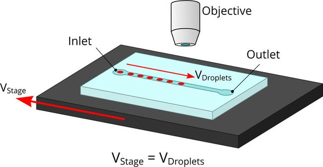
Figure 4. Moving shot image of droplets captured using an Nucleus MVR inverted microscope. The use of a global shutter camera yields true-to-life round droplet images.
Maintaining Focus
High magnification objectives between 40-63x have a small depth of field of about 1 μm. It is often not possible to achieve sharp focus across the entire chip. For automated imaging of multiple locations on a single chip, or imaging a series of chips, a motorized focus mechanism is a necessity.
Sharpness-based autofocus algorithms are widely available and have been implemented in the open-source microscopy software package μManager. By capturing a series of images at different Z positions, convolving them with a filter and maximizing the sum of squares over the entire image, the z position with the greatest sharpness can be identified. While effective for general-purpose microscopy, these algorithms may not not provide microfluidics users with the fine control required to select which structures are focused on. These focus methods also require the objective to start very close to the final focus position. Focusing on moving droplets is especially challenging for these algorithms as droplets may move out of frame during the Z stacking process. One way around this is to specify a region of the image where to compute the sharpness and then apply a fixed offset from say the channel wall.
A more robust method of focusing uses the reflection of an IR laser off an interface of the chip like the glass coverslip. These systems excel at maintaining a focus point relative to this reflective surface. Structured light or intentionally astigmatic laser beams are frequently used to measure the distance by observing the shape of the returned laser spot. While expensive, they offer the best performance on the market today. The optical system of the Nucleus MVR microscope can be adapted to support laser autofocus using the optional MJB25 (Fig.5) module which provides an additional port, filter and dichroic in the optical path’s infinity corrected space.
It is also possible to completely bypass this issue by creating a focus offset mapping for the sample. This effectively comprises a direct calibration of stage and sample planarity errors. This technique may not be suitable for high-magnification optics. Thermal variations in the microscope environment will cause expansion of the components of the setup on the order of 10 ppm which will change the offset table dramatically.
Fluorimetry
Fluorescent labeling is a ubiquitous technique in modern biology. It is widely used for functional assays, genomics, transcriptomics and proteomics. Microfluidic systems frequently require the simultaneous observation of multiple fluorophores at high-throughput which is difficult with a standard photomultiplier tube (PMT) epi-fluorescence setup. Nucleus microscopes (Fig.5) are cost effective and flexible platforms for conducting high-throughput epifluorescence imaging. Nucleus microscopes share a common control protocol with a wide range of Zaber motion control devices, greatly simplifying the development and setup of fluorescence-based microfluidic systems.
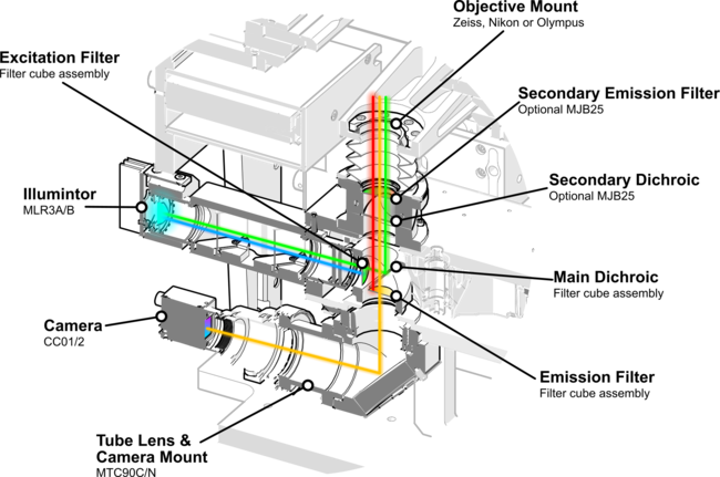
Figure 5. The Nucleus MVR inverted microscope’s epifluorescence imaging optical path enables automated multi-channel fluorometry with its integrated three-channel LED illuminator and motorized filter cube turret.
While not as sensitive as PMT, modern CMOS sensors can achieve quantum efficiencies beyond 80%. Using a motorized filter wheel it is possible in some cases to spread out the acquisition of different wavelengths over time using exposure stacking and dramatically reduce the complexity of fluorescence imaging systems. This is particularly useful in combination with the moving shot or stroboscopic techniques described above.
Another important consideration for fluorescence imaging of microfluidics is minimizing the background fluorescence of substrate materials to maximize contrast. Cyclic olefin copolymer (COC) is a common material for constructing microfluidic chips with low intrinsic fluorescence. Advanced methods such as time-resolved fluorescence can be applied to further improve contrast.
Summary
Imaging microfluidic devices in action is critical to accurately validate and control their operation and read their results. Sourcing, configuring and synchronizing discrete motion control and illumination systems with expensive high speed cameras can be a challenging and time consuming task. The Nucleus microscopy platform lets you integrate these systems into a single easy to use instrument. By providing simple motion control and camera synchronization, the Nucleus platform and the Zaber Motion Library make advanced imaging techniques like stroboscopic and moving shot imaging easily accessible. These imaging modes eliminate the need for specialized and expensive high-speed cameras, reducing system costs and making microfluidic technologies more accessible than ever.