Lab Automation: Customizable Animal Tracking System for Under $10k
By Dan Rudmin, Mechanical Engineering Team, and Skyler Olsen, Software Team
Last updated on Nov. 14, 2025
Researchers all over the world conduct experiments requiring the precise tracking of small animals such as mice, zebrafish, or fruit flies. To ensure natural behavior, it's essential to allow the animals move freely. This can be especially challenging when wired sensors are attached to the animal or a high-magnification imaging system needs to follow them closely. As off-the-shelf solutions are limited, a custom-built system is ideal and provides the most flexibility. To assist researchers in this endeavor, we've developed a customizable benchtop system integrating our modular gantry systems and machine vision.
In this article, we discuss key design considerations, hardware choices, and provide practical assembly tips. We discuss software choices and provide all the Python code needed to recreate this demo system.
Use Case & Challenge
Three key technical requirements:
1. Flexible and Modular Design
The system should adapt to various experimental setups. For demonstration purposes, it should fit on a standard table and be easily reconfigurable for different environments or research needs. Its modular design should allow researchers to swap components like tracking tools and instruments, facilitating upgrades and ensuring ongoing relevance as research evolves.
2. Real-Time Tracking of Dynamic Subjects
The system must provide reliable real-time tracking, effectively managing the unpredictable nature of animal behavior while ensuring that the end effector remains focused on the subject.
For this demo, a HEXBUG toy was used as the target in lieu of a live animal. HEXBUG toys move around randomly and are a good test of the system’s ability to follow unpredictable behavior. We included several toys in the tracking area to show how well the system tracks its designated target. To simulate an end-effector, we used a spotlight, allowing us to visually track its movement as it followed the target.
3. Cost-Effective & Straightforward Set-Up
To make the system accessible to a wide range of labs, we prioritized using cost-effective components and ensuring a straightforward setup and programming process. This allows researchers to easily configure the system and make quick adjustments as needed during experiments.
Solution
A machine vision based tracking system that offers reliable, real-time tracking and can be easily integrated into various experimental setups. Built with a standard Zaber XY gantry, the system should take less than a week to set up and program with basic technical knowledge and guidance from this article. All for under $10,000 USD.
Figure 1: Object tracking system with camera view.
Hardware
To ensure a modular system that could be easily adapted in the future, the Zaber LC40 XY gantry system, built on a T-slot aluminum frame, is an ideal choice. The LC40 series of linear stages are designed for rapid movement of medium loads over distances ranging from 30 mm to over 3 meters.
1. Motion System
- Zaber LC40 Dual Motor Gantry System: This is the foundation of the hardware setup. It consists of three LC40 linear actuators controlled by a multi-axis Zaber X-MCC controller. X-MCC controllers feature a plug-and-play USB interface.
Figure 2: Exploded view of Zaber LC40 Gantry System.
- Design & Configuring the System: Zaber’s online gantry configurator tool makes designing a gantry system quick and easy. For this system, we selected a 650 mm x 300 mm gantry with dual motors on the lower axis. The motors allow for greater thrust and acceleration to ensure accurate tracking of fast moving targets. While this isn't strictly necessary for the small size of this example system, it ensures that the design remains flexible and modular, making it easy to adapt as the system scales up or requirements change. This tool also provides up-to-date lead times and pricing helping you to effectively plan your timelines and budgets.
2. Off-the-Shelf and Custom Components
A few components were custom-made in-house for convenience. Most of them are tailored specifically for our demo and may not be necessary for other research setups.
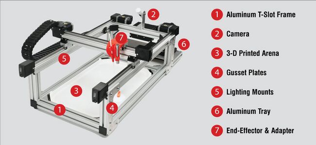
Figure 3: Off-the-shelf components and custom components.
- Aluminum T-Slot Frame
- Constructed mostly from 4040 T-slot framing and off-the-shelf hardware
- Corner brackets to save time on assembly/disassembly
- Vision System - Logitech Brio 500 Webcam
- Inexpensive solution with a generic camera interface which simplifies software integration.
- Large field of view(90°) that allowed the entire monitoring space to be in frame.
- ¼-20 thread for mounting to the frame.
- Arena
- 3-D Printed platform to constrain the available moving space of our test subjects (HEXBUGs).
- The backside has a chessboard pattern for calibrating the camera parallax.
- Gusset Plates
- Holds the frame and motion system together while adding rigidity.
- Lighting Mounts
- 3-D printed mounts that slot in underneath each X-Axis stage.
- Aluminum Tray
- ⅛” aluminum waterjet cut plate to mount any unexpected accessories.
- End-effector and adapter
- The spotlight is attached to the Y-axis carriage using a 3D-printed adapter. The carriage includes multiple M4 threaded holes, offering flexibility for various mounting options.
A detailed bill of materials is available in the appendix.
Assembly Notes
To assemble the gantry, follow the detailed instructions in the LC40 Gantry User Manual.
To assemble the support frame, each part number is provided in the bill of materials.
Pro Tips:
- It is critical that the 3 cross beams are the exact same length. Differences in length will cause spreading of the motion system and may make it bind up.
- A simple way to add rigidity to the system is to connect the extrusions of the frame via gusset plates on each of the joints. While we custom made these, alternatives can be easily found on sites such as McMaster-Carr.
- Adding rubber feet to the system is important for reducing vibrations and noise.
- Before bolting the frame parts together, ensure the LED light strip cables and any other cables running through the frame are properly routed into the back of the gantry. Since USB plugs or other cables do not fit through the joints where the extrusions meet, you won’t be able to route these cables afterward without disassembling the gantry. This step avoids the need to take the gantry apart again just to clean up cable management—a small but tedious task that’s best to avoid (as we learned first-hand).
- When securing the frame, turn off the gantry first. Then, manually push the Y-axis by hand to one end of the gantry and tighten the bolts on that side. Next, shift the Y-axis to the opposite end and tighten the bolts there. This approach helps enforce consistent spacing between the Y-axis and cross members.
Figure 4: Bolting together system to enforce consistent spacing.
Software Control Steps
1. Find the HEXBUG in a frame captured from the camera
A straightforward algorithm detects the HEXBUG by identifying its distinctive color. The hue of the bug is hardcoded, allowing the algorithm to search for the largest area of that color in the frame. First, the image is converted from the BGR (blue-green-red) color space to HSV (hue-saturation-value). This conversion facilitates detection since color is defined on the single hue dimension, rather than being split across 3 different dimensions. After the conversion, openCV's inRange function is used to find regions in the image that are of the specified color. It returns a new black and white image where anything of the specified color is white, and everything else is black.
def find_by_color(img, low_H: int, high_H: int):
       """Converts an image to black and white targeting the specified color"""
       low_hsv = np.array([low_H, 25, 25])
       high_hsv = np.array([high_H, 255, 255])
       img_hsv = cv.cvtColor(img, cv.COLOR_BGR2HSV)
       img_bw = cv.inRange(img_hsv, low_hsv, high_hsv)
       return img_bw
Next, use OpenCV to extract contours from the white patches in the image. The contours are filtered to remove those below a minimum size, and if no contours are found, the process exits early. Otherwise, the algorithm returns the largest contour wrapped in a custom Mouse class, which includes its size.
def find_mouse(img_bw: cv2.UMat) -> Mouse | None:
   contours, _ = cv2.findContours(img_bw, cv2.RETR_LIST, cv2.CHAIN_APPROX_SIMPLE)
   blobs = [Mouse(contour) for contour in contours]
   mice = [mouse for mouse in blobs if mouse.size() > MIN_MOUSE_SIZE]
   if len(mice) == 0:
       return None
   biggest_mouse = max(mice, key=lambda mouse: mouse.size)
   return biggest_mouse
2. Convert the HEXBUG’s position within the frame into a real-world position in the arena using a 2D camera
Once a contour is detected, its pixel location must be translated from the camera's coordinate system into real-world coordinates for effective gantry tracking. To achieve this, the camera must be calibrated. We used a chessboard pattern of known dimensions. By capturing an image of this pattern and processing it with OpenCV's calibrateCamera function, essential information is obtained, including the camera matrix, distortion parameters, and pixel coordinates of the chessboard's corners. Next, use OpenCV’s solvePnP function, which generates two crucial outputs: the translation vector (t) and the rotation matrix (r). These matrices allow us to convert a point in world coordinates into its corresponding pixel location in the camera’s view using the formula:
Where c represents the pixel coordinates and p represents the world coordinates. Assuming the target remains on the table’s surface, this relationship can be used to accurately find the real-world position p from the pixel coordinates c detected earlier.
3. Move the gantry end-effector to that position
Moving the gantry to follow the target is straightforward once the HEXBUG's position in the arena is known. Use an absolute move command, accounting for the gantry's offset, and gather asynchronous methods so that both X and Y movements start simultaneously.
   async def move_abs_mm(self, point: Vec2, accel: float | None = None):
       """Moves the gantry"""
       await asyncio.gather(
         self._x.move_abs_mm(X_AXIS.origin + point.x * X_AXIS.scale, accel),
         self._y.move_abs_mm(Y_AXIS.origin + point.y * Y_AXIS.scale, accel),
       )
While synchronous commands could be used, async provides an optimization by allowing the system to handle multiple tasks in parallel.
Achieving Smooth Motion
For smooth tracking, the code must run quickly, sending frequent updates to the gantry. However, command transmission and camera processing can introduce delays (up to 50 ms), making the motion appear jittery as the gantry constantly lags behind the target. To solve this, the camera and movement processes are split into two independent tasks: one handles image capture and target detection, while the other sends movement commands. Running these on separate threads significantly reduces iteration time, resulting in smoother motion. In Python, this is achieved by running the two tasks asynchronously, so by the time one move command is processed, the next target position is ready.
Conclusion
The object detection and tracking demo system presented here provides a versatile and affordable tool to support studies using optogenetics, behavioral tracking. and spatial learning based methods. The system is capable of responding to rapid and unpredictable behaviors, ensuring the system closely tracks your targets.
Through a user-friendly assembly process and open-source programming, the LC40 gantry system can accommodate diverse experimental setups for researchers and can be adapted as projects evolve.
Appendix
Download SolidWorks Model (.zip)
Bill of Materials
| Source | Item | Description | Qty | Price/unit (USD) | Subtotal (USD) |
|---|---|---|---|---|---|
| Zaber | Motion System | LC40 Dual Motor Gantry (650mm x 300 mm) | 1 | $8,663.00 | $8,663.00 |
| 80/20 | 1000 mm T-Slot Aluminum Extrusion | 40-4040-Lite | 2 | $36.59 | $73.18 |
| 80/20 | 165 mm T-Slot Aluminum Extrusion | 40-4040-Lite | 4 | $8.02 | $32.08 |
| 80/20 | 370 mm T-Slot Aluminum Extrusion | 40-4040-Lite | 3 | $13.22 | $39.66 |
| McMaster-Carr | T-Slotted Framing Corner Bracket | 6812N831 | 8 | $10.19 | $81.52 |
| McMaster-Carr | Extrusion caps | 5537T24 | 4 | $2.13 | $8.52 |
| McMaster-Carr | Rubber feet | 9540K751 | 4 | $6.90 | $27.60 |
| McMaster-Carr | Flush 90 Degree Angle Bracket (Alternative to custom gusset plates) | 3136N924 | 8 | $20.18 | $161.44 |
| Amazon | LED Lights | N/A | 2 | $10.00 | $20.00 |
| Logitech | Vision System | Brio 500 Webcam | 1 | $130.00 | $130.00 |
| Custom | Extra Mounting Plate | N/A | 1 | N/A | N/A |
| Custom | Camera Mount | N/A | 1 | N/A | N/A |
| Custom | Chess Board for Calibration | N/A | 1 | N/A | N/A |
| $9,237.00 |
Table 1: Bill of Materials
Note: Prices in this bill of materials are accurate as of publication and may change. Verify current pricing before purchasing.