Software/MicroManager

From ZaberWiki
Jump to navigation Jump to search

Micro-Manager is a free, open-source software package that provides an easy-to-use interface for microscope automation. It supports a range of microscopes, cameras, and motion control devices, and works with ImageJ image processing software.

Compatibility

Currently Micro-Manager has five kinds of drivers for controlling Zaber devices: Stage, XYStage, Filter Wheel, Filter Cube Turret, and Illuminator. These drivers require Zaber devices to have Firmware v6.06 or later and be set to use the Zaber ASCII protocol. Additionally, the XYStage driver requires that at least two devices are connected to a port, the Filter Wheel driver requires that a X-FWR filter wheel is connected, the Filter Cube Turret requires a component of the MVR microscope, and the Illuminator requires an X-LCA series LED controller.

Download and Installation

You can download Micro-Manager here We recommend using the latest version of Micro-Manager 2.0.

Any Windows version of Micro-Manager released after the 26th of August 2023 requires additional files installed by Zaber Motion for Micro-manager installer. Please run the installer after you've installed Micro-Manager.

Set Up

Zaber Device

If you're using Zaber stand-alone controllers, first ensure that they are configured by following the easy set-up page here: https://www.zaber.com/products/product_group.php?group=X-MCB2&tab=Easy%20Set-up. In particular, ensure the controller has optimized settings by setting the correct peripheralid setting. You can find more information on how to set the peripheral ID in Zaber’s Protocol Manuals (ASCII).

If you're using Zaber devices with built-in controllers, follow the easy set-up page here: https://www.zaber.com/products/product_group.php?group=X-FWR-E&tab=Easy%20Set-up.

Micro-Manager

You can download the latest version of Micro-Manager here: https://micro-manager.org/Download_Micro-Manager_Latest_Release and this documentation can also be viewed on the Micro-Manager site here: https://micro-manager.org/Zaber

When Micro-Manager first starts up, it will ask you to load the demo configuration file; click 'Yes'. Next, under the 'Tools' tab, run the 'Hardware Configuration Wizard' and choose to create a new Configuration file. Locate the 'Zaber' folder in the device list.

Setting Up A Two-Axis System

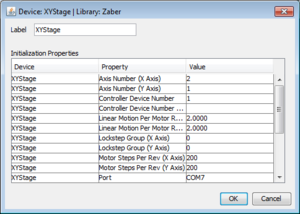
From the Zaber folder in the device list, select XYStage | Zaber XY Stage.

Select add, and you will be prompted to enter the following initialization properties:

Axis Number (X Axis): This refers to the axis number connected to your X axis. Enter a value of 1 if the X axis uses an integrated controller or single-axis controller. If the X axis is connected to a multi-axis controller, such as the X-MCB2 or A-MCB2, the value will be either 1 or 2.
Axis Number (Y Axis): This refers to the axis number connected to your Y axis. Enter a value of 1 if the Y axis uses an integrated controller or single-axis controller. If the Y axis is connected to a multi-axis controller, such as the X-MCB2 or A-MCB2, the value will be either 1 or 2.
Controller Device Number: The device address of the X-axis, or if both axes are connected to a multi-axis Zaber controller, such as the X-MCB2 or A-MCB2, the controllers device address.
Controller Device Number (Y Axis): The device address of the Y-axis, if the axes are on different controllers or or have integrated controllers. Leave this blank if both axes using a multi-axis Zaber controller, such as the X-MCB2 or A-MCB2.
Linear Motion Per Motor Rev (X Axis): This value is found on the stage's specification webpage.
Linear Motion Per Motor Rev (Y Axis): This value is found on the stage's specification webpage.
Lockstep Group (X Axis) and Lockstep Group (Y-Axis): If you have configured a multi-axis device to have a group of axes move in lockstep, enter the lockstep group number here to use the lockstep group as your X or Y axis. You must still set the X or Y Axis Number to be one of the axes in the lockstep group - this axis will be used for position measurement. You must use external software such as Zaber Console or a serial terminal to put the device into lockstep mode - for more information please see the Zaber ASCII Protocol Manual. You can have both axes refer to different lockstep groups, have one be a lockstep group and one a normal axis, or have both be normal axes (the default). If you have not enabled lockstep mode on your devices, enter zero for the Lockstep Group properties.
Motor Steps Per Rev (X Axis): The value found on the stage's specification webpage (typically 200).
Motor Steps Per Rev (Y Axis): The value found on the stage's specification webpage (typically 200).
Zaber Serial Port: The COM port the device is connected to.

If you are using Zaber’s two-axis X-MCB2 external controller with an ASR microscope stage, you are able to set the physical limits by adjusting the home and away sensors. For more information on setting the limits, read the instructions here: https://www.zaber.com/wiki/Manuals/ASR#Setting_Home_and_Away_Sensors. Once the limits have been moved, the controllers travel range must also be set.

Set the controllers minimum and maximum limits of travel by going to 'Tools', selecting 'Stage Position List', and pressing 'Set Origin'. Repeat this process if the limits are moved.

If an axis is reporting the peripheral inactive (FZ) warning flag, the driver will attempt to activate the peripheral when the hardware configuration is loaded in Micro-Manager. If this fails, it will set the peripheral to the unused state and that axis will not be usable by Micro-Manager. If you reconnect the peripheral or connect a different one with Micro-Manager open, you can try reloading the hardware configuration to activate it.

Zaber XY Stage

Sample XY Stage Configuration

Setting Up A Single-Axis System

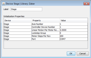
From the Zaber folder in the device list, select Stage | Zaber Stage.

Select add, and you will be prompted to enter the following initialization properties:

Axis Number: Enter a value of 1 if the X axis uses an integrated controller or single-axis controller. If the X axis is connected to a multi-axis controller, such as the X-MCB2 or A-MCB2, the value will be either 1 or 2.
Controller Device Number: The device address of the stage.
Linear Motion Per Motor Rev: This value is found on the stage's specification webpage.
Lockstep Group: If you have configured a multi-axis device to have a group of axes move in lockstep, enter the lockstep group number here to use the lockstep group as your single axis. You must still set the Axis Number to be one of the axes in the lockstep group - this axis will be used for position measurement. You must use external software such as Zaber Console or a serial terminal to put the device into lockstep mode - for more information please see the Zaber ASCII Protocol Manual. If you have not enabled lockstep mode on your devices, enter zero for the Lockstep Group property.
Motor Steps Per Rev: The value found on the stage's specification webpage (typically 200).
Zaber Serial Port: The COM port the device is connected to.
Zaber Stage

Sample Stage Configuration

If an axis is reporting the peripheral inactive (FZ) warning flag, the driver will attempt to activate the peripheral when the hardware configuration is loaded in Micro-Manager. If this fails, it will set the peripheral to the unused state and that axis will not be usable by Micro-Manager. If you reconnect the peripheral or connect a different one with Micro-Manager open, you can try reloading the hardware configuration to activate it.

Setting Up A Filter Wheel

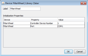
From the Zaber folder in the device list, select Filter Wheel. If you do not see Filter wheel as an option, update to the latest nightly build of Micro-Manager.

Select add, and you will be prompted to enter the following initialization properties:

Controller Device Number: The device address of the Filter Wheel.
Zaber Serial Port: The COM port the device is connected to.
Zaber Filter Wheel

Sample Filter Wheel Configuration

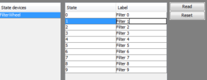
After Micro-Manager has finished the filter wheel detection process, you will have the option to label each of the filter positions.

Once you have added the filter wheel, Micro-Manager will automatically run a filter wheel detection routine. This lets Micro-Manager know how many filters are available.

If you change the filter holder in your device to one with a different size or number of positions (eg. 7 position filter holder to a 10 position filter holder), use the Hardware Configuration Wizard to re-run the filter wheel detection command.

Zaber Filter Wheel Label

Sample Filter Wheel Label Screen

Setting Up A Filter Cube Turret

Setting up a Filter Cube Turret is identical to Setting Up A Filter Wheel.


Setting Up An Illuminator

From the Zaber folder in the device list, select Illuminator. If you do not see Illuminator as an option, update to the latest nightly build of Micro-Manager.

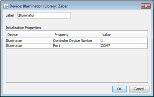
Select add, and you will be prompted to enter the following initialization properties:

Controller Device Number: The device address of the Illuminator.
Zaber Serial Port: The COM port the device is connected to.
Zaber Illuminator

Sample Illuminator Configuration

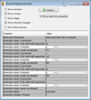
After finishing your configuration, you will be able to control the illuminator via presets and the shutter open/close button. Each LED has an intensity property that controls the output luminous flux as a percentage of the maximum supported by the LED. There are also several read-only properties that can be used to check that the LED is present and its properties.

The image at right shows all of the properties provided by a four-channel illuminator. The "Number of lamps" property indicates how many LEDs the device is capable of driving. For each LED, starting at 1, there are properties that indicate whether the lamp is present and what its peak wavelength and FWHM (Full-Width Half Magnitude) are. FWHM is a measure of how broad the lamp's output spectrum is. Peak wavelength and FWHM are measured in nanometres. Note that a white LED will report zero for both wavelength properties but will still show as being connected.

If an LED overheats, it will automatically be shut off and an error will occur the next time Micro-Manager sends the Illuminator a command. You should close the shutter and wait a while for the LED to cool down; it should automatically become usable again when the temperature is reduced.

Zaber Illuminator Properties

Sample Illuminator properties

Note: Your illuminator device must have Firmware version 7.14 or later to be compatible with the Micro-Manager builds after 2020-10-07. See the Zaber Console User Guide for firmware update instructions.

Note: The X-LCA illuminator is capable to automatically detecting connection and disconnection of LEDs and the types of LEDs connected, but the Micro-Manager driver does not support live updates of this information while enabled. If you want to rearrange, add or remove the LED connections, you should reload your hardware configuration in Micro-Manager immediately after doing so; the driver will check for unconfigured, new or missing LEDs at configuration load time and will attempt to automatically activate or deactivate changed LEDs as needed.

Setting Up An Objective Changer

From the Zaber folder in the device list, select Objective Changer. If you do not see Objective Changer as an option, update to the latest nightly build of Micro-Manager.

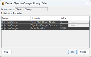
Select add, and you will be prompted to enter the following initialization properties:

Focus Stage Device Number: The device address of the focus stage (stage moving the objective up and down).
Objective Changer Device Number: The device address of the objective changer (X-MOR).
Zaber Serial Port: The COM port the device is connected to.
Objective Changer Sample Configuration

Objective Changer Sample Configuration

After Micro-Manager has finished the objective changer detection process, you will have the option to label each of the objectives.

Control

There are several ways to control the position of the stage:

  • Stage Control Plugin
  • Mouse Movement (click and drag in Snap/Live Window)
  • Filter Wheel Presets
  • Using the manual adjustment knobs on the controller

You can adjust the speed and acceleration of each device through the Tools > Device/Property Browser dialogue box.

Stage Control Plugin

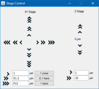
The stage control plugin can be found under Plugins > Device Control > Stage Control. This will open controls to move using the XYStage driver (on the left), or the Stage driver (on the right).

You can map distances for fine, medium, and coarse moves.

Stage Control interface

Stage Control interface

Mouse Movement

Select Tools > Mouse Moves Stage and you will be able to move an XYStage in the Snap/Live Window with your mouse. Click and hold, and the stage will follow the mouse position. You can also double click a location anywhere within the window and the stage will move to center the window on that point.

Before using this method, the pixel size must be calibrated. To do this:

  1. Make sure the microscope and camera are set up and focused on the object you want to view.
  2. Select Tools > Pixel Size Calibration and click New to create a new calibration setting.
  3. Enter the properties that will affect the calibration, particularly the camera resolution.
  4. Estimate the size of a pixel size in μm, enter it in μm/pixel, and click OK to exit the calibration window.
  5. Under Tools select Mouse Moves Stage and select the hand tool from the ImageJ window.
  6. In the Snap/Live Window, find a small distinct point on the image, and click and drag it across the window. If the point ends up ahead of the mouse cursor/hand tool, you will need to reduce the μm/pixel setting. If it ends up behind the cursor, you will need to increase the setting. Repeat until the point stays directly underneath the mouse cursor.

Filter Wheel Presets

After adding a Filter Wheel device, there should be an entry for it under Configuration settings. Under the Preset, there will be a drop-down menu with entries for each filter wheel label or number. Select one to move to the corresponding position.

Manual Adjustment Knobs

Zaber devices can also be controlled using their manual control knobs. Pushing and holding the knob for one second switches between velocity and displacement mode. Pushing the knob while the stage is moving stops the stage.

Scripting

Micro-Manager has a built-in scripting interface accessible through Tools > Script Panel. For Information on Micro-Manager’s programming features, check their guide: [1] .

Here is a sample script for controlling Zaber’s ASR two-axis stage using the XYStage driver:

mmc.unloadAllDevices();

mmc.loadDevice("asr", "Zaber", "XYStage");
mmc.setProperty("asr", "Zaber Serial Port", "COM1");

// For this example we assume there is a single controller with
// two peripheral axes connected, and we use the default settings
// for the axis numbering. This line shows how to set the
// address of the controller.
mmc.setProperty("asr", "Controller Device Number", "1");
mmc.initializeAllDevices(); 

// Move to the home position.
// Note this command also causes the device to find the limits of its
// motion, so it will move over its full range. Remove any obstructions
// from the stage's path before running this script!
mmc.home("asr");

// Draw a square. Note the setXYPosition calls do not block
// Include waitForDevice calls after each move to wait for it to finish
mmc.setXYPosition("asr", 0, 0);
mmc.waitForDevice("asr");  

mmc.setXYPosition("asr", 0, 10000);
mmc.waitForDevice("asr");  

mmc.setXYPosition("asr", 10000, 10000);
mmc.waitForDevice("asr"); 

mmc.setXYPosition("asr", 10000, 0);
mmc.waitForDevice("asr");

mmc.setXYPosition("asr", 0, 0);
mmc.waitForDevice("asr");

mmc.unloadAllDevices();


When scripting using the Filter Wheel or Filter Cube Turret driver, Micro-Manager considers the device to be a state device. This means that it has a number of defined physical states which represent each filter. Following is a sample script for the filter wheel:

mmc.unloadAllDevices();


mmc.loadDevice("wheel", "Zaber", "FilterWheel");
mmc.setProperty("wheel", "Zaber Serial Port", "COM1");
mmc.initializeAllDevices();

int numPositions = mmc.getNumberOfStates("wheel");
gui.message("Filter wheel has " + numPositions.toString() + " positions."); 

gui.message("Moving to position 0");
mmc.setState("wheel", 0);
mmc.sleep(250);

for (int i = 1; i < numPositions; ++i)
{
   gui.message("Moving to position " + i.toString());
   mmc.setState("wheel", i);
   mmc.sleep(100);
} 
	
mmc.sleep(250); 

for (int i = numPositions - 2; i >= 0; --i)
{
   gui.message("Moving to position " + i.toString());
   mmc.setState("wheel", i);
   mmc.sleep(100);
}


When scripting the Illuminator you can read device properties to determine how many LEDs are present, what their wavelengths are, and you can write the intensity properties to independently control the output flux of each LED. The Illuminator is considered a shutter device in Micro-Manager, so you can use shutter control functions to turn the LEDs on and off. Here is an example script that detects LEDs and turns them on one at a time, except for any that fall outside the visible spectrum (to avoid accidental eye damage):

mmc.unloadAllDevices();

// Set up the illuminator. This assumes an
// X-LCA at Zaber device address 1.
mmc.loadDevice("lca", "Zaber", "Illuminator");
mmc.setProperty("lca", "Zaber Serial Port", "COM1");
mmc.setProperty("lca", "Controller Device Number", "1");
mmc.initializeAllDevices(); 

// Turn off the lamps.
mmc.setShutterOpen("lca", false);

// Get the possible number of lamps.
numLamps = Integer.parseInt(mmc.getProperty("lca", "Number of lamps"));
int[] lamps = new int[numLamps];
int lampIndex = 0;

gui.message("Device supports up to " + numLamps + " lamps.");

for (int i = 0; i < numLamps; i++)
{
   // Find all connected lamps in the visible range (to avoid eye damage).
   if (Integer.parseInt(mmc.getProperty("lca", "Lamp " + (i + 1) + " connected")) == 1)
   {
       wavelength = Double.parseDouble(mmc.getProperty("lca", "Lamp " + (i + 1) + " peak wavelength"));
       if ((wavelength >= 400.0) && (wavelength <= 700.0))
       {
           gui.message("Lamp " + (i + 1) + " has a peak wavelength of " + wavelength + " nm and will be tested.");
           lamps[lampIndex] = i + 1;
           lampIndex++;
       }
       else
       {
           gui.message("Lamp " + (i + 1) + " has a peak wavelength of " + wavelength + " nm and will NOT be tested.");
       }

       // Also set all intensities to 0 since we're going to use one at a time.
       mmc.setProperty("lca", "Lamp " + (i + 1) + " intensity", 0.0);
   }
   else
   {
       gui.message("Lamp " + (i + 1) + " is not connected.");
   }
}

// Now turn one each lamp one at a time.
numLamps = lampIndex;
gui.message("Now testing " + numLamps + " lamps for two seconds each.");

for (int i = 0; i < numLamps; i++)
{
   int lampNumber = lamps[i];
   gui.message("Lamp " + lampNumber);
   mmc.setProperty("lca", "Lamp " + lampNumber + " intensity", 100.0);
   mmc.setShutterOpen("lca", true);
   mmc.sleep(2000);
   mmc.setShutterOpen("lca", false);
   mmc.setProperty("lca", "Lamp " + lampNumber + " intensity", 0.0);
}

// Make sure all lamps are off.
mmc.setShutterOpen("lca", false);

mmc.unloadAllDevices();

gui.message("Done.");