Zaber X-Series Shield for Arduino: Hardware Overview
This document describes the hardware on Zaber's X-Series Shield for Arduino (X-AS01, or the Shield in short).
Power Source
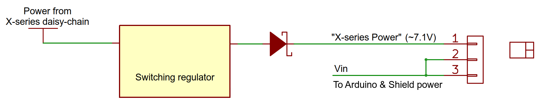
Zaber X-Series devices can share power between them. This can also be used to power the Shield and the Arduino. The Shield has an on-board switching regulator that converts the 24-48 V DC power from the X-Series daisy-chain to ~7 V with a maximum output of 500 mA which the Arduino and the Shield can use. The Shield always draws its power from its Vin pin (see block schematic below), so if you want to power the Shield and the attached Arduino from a Zaber X-Series device, put the Power Source jumper in the "X-Series Power" position. If you'd prefer to power the Arduino using the barrel jack power input or the Vin pin on the Arduino, keep the jumper in the "Vin/USB" position.
Warning: DO NOT connect power to the barrel jack power input or the Vin pin on the Arduino when the jumper is in the "X-Series Power" position. This will connect 7 V from the on-board regulator to the Arduino's Vin, and may damage your power source.
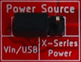 | 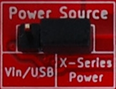 |
| Arduino and X-Series Shield powered from Vin or USB | Arduino and X-Series Shield powered from X-Series device |
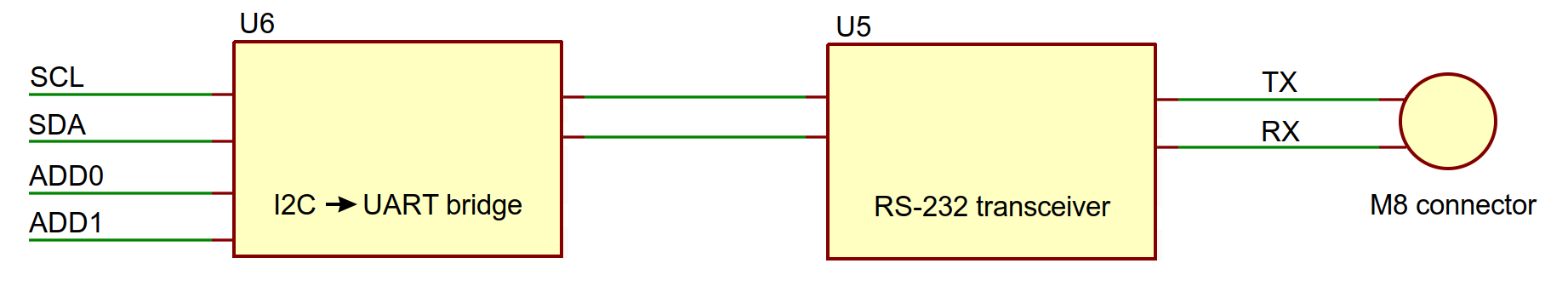
Communication
The X-Series Shield is designed to leave native Arduino serial ports free. To accomplish this, the Arduino communicates with the Shield using I2C. The Shield uses an I2C→UART bridge (U6) and an RS-232 transceiver (U5) to translate this to RS-232 serial communication with the Zaber device.
The I2C→UART bridge needs to be assigned an address, and the Shield lets you do this with two I2C Address selection jumpers. The default address of AA (hex value 0x90) will work in most cases, but there are four options to choose from. To change addresses, you must power cycle the board after moving the jumpers – simply resetting will not work. If you lose your jumpers, each address bit will default to A.
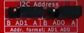 | Address in code: ZABERSHIELD_ADDRESS_AA Hex value: 0x90 |
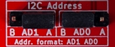 | Address in code: ZABERSHIELD_ADDRESS_AB Hex value: 0x92 |
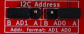 | Address in code: ZABERSHIELD_ADDRESS_BA Hex value: 0x98 |
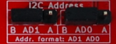 | Address in code: ZABERSHIELD_ADDRESS_BB Hex value: 0x9A |
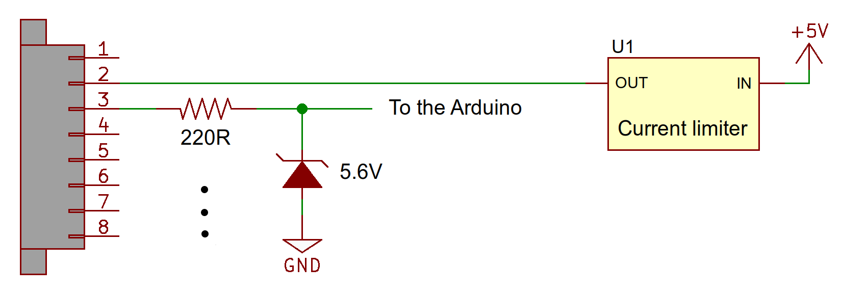
"Ruggedized" I/O on the Terminal Block
The Shield includes a terminal block connection to four digital pins and two analog pins. Some short-circuit and out-of-range voltage protection circuitry is included (see schematic below). Due to the clamping diodes used, the analog pins can only go up to 4.98 V (instead of 5 V) and the highest analog value that can be read is 1020 (instead of 1024). If this is a problem, use the unprotected I/O directly on the Shield's pin headers, or desolder the Zener diode on that analog pin.
The 5 V output is protected by a 150±10 mA current limiter (U1). The output is disabled as this threshold is reached; the output gets disconnected from 5 V and quickly goes to 0 V. If you are using the 5 V from this connector and notice that it is no longer working, check your circuit for shorts and try reducing the current load. The current limiter should automatically re-enable once the load current is within range.
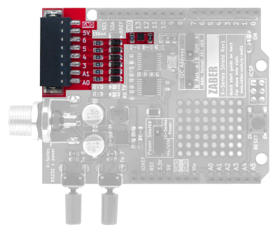
Switches
The two push-button switches on the Shield are useful for starting and stopping motion sequences, so that your system doesn't move unexpectedly as soon as the Arduino is powered. The switches are connected to digital pins 7 and 8, so make sure you have nothing else connected to the corresponding pin if you are planning to use one of them. To read a push-button switch, configure pin D7 or D8 as an input:
pinMode(pin, INPUT); // set pin to input
There's no need to enable the pull-ups, since there are 47kΩ pull-ups on the Shield.