10x Your Imaging Throughput with Zaber Stages and TDI imaging
By Stefan Martin, Mechanical Engineering Team & Mike Fussell, Life Sciences Product Manager
Last updated on May 26, 2025
In many life science research and industrial biology applications, imaging throughput is a critical performance metric. Capturing more data faster can greatly reduce the duration of experiments, empower screening facilities to cover many more compounds and cell lines, and deliver a significant competitive advantage for OEM device manufactures. Time Delay Integration (TDI) imaging using sCMOS cameras is one way to exponentially increase your microscope imaging output.
In this article we address:
- Performance benefits and advantages of TDI over the state-of-the-art area scan cameras, and how to maximize these advantages for your application
- Three different ways of synchronizing cameras with motion control
- Detailed step-by-step instructions for setting up your own TDI imaging system using Zaber’s Nucleus microscope with high-speed linear motor stages and a Dhyana 9KTDI camera to deliver exceptional imaging throughput.
Introduction to TDI Imaging
TDI imaging builds on the basic principle of line scan imaging. Unlike the more familiar and more common area scan cameras which have many horizontal rows and capture a large 2D area with each exposure, line scan cameras have a single row of pixels. This row of pixels is triggered to acquire a thin image slice every one pixel of distance that the target is moved relative to the camera. A 2D image is formed by joining these slices together. While they may only capture a single row of pixels at a time, line scan cameras can be triggered at rates as high as several hundred kHz.
TDI cameras take this basic method and add multiple lines. The camera is still triggered at every one pixel of distance moved relative to the target, resulting in each slice being captured once by every row as scan progresses. These duplicate exposures of each slice are then summed together, resulting in a much brighter image than would be possible given the same exposure time on a traditional line scan camera.
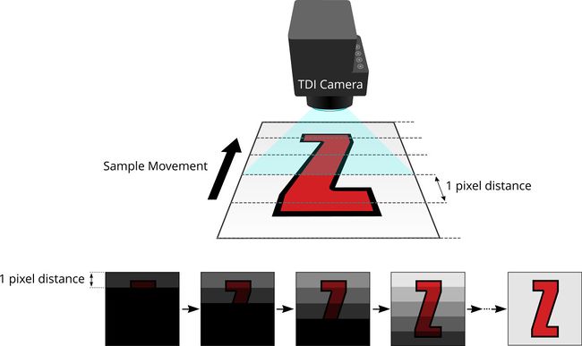
Figure 1. Summation of multiple short exposures of each line generates a well exposed image
This summing process enables TDI cameras to deliver very high scanning speeds. For example, if a 5 ms total acquisition time is required to capture an actionable image, a single line camera could only move at a rate of 1 pixel every 5 ms. A hypothetical TDI camera with 5 horizontal lines moving at 1 pixel every 1 ms and scanning each line 5 times, would yield the same 5 ms total exposure time, while scanning 5x faster than the single line camera. The Tucsen Dhyana 9KTDI camera has 256 horizontal lines. Continuous scanning with a TDI camera delivers several key advantages. These are:
- Imaging at a constant velocity dramatically reduces resonant vibrations to deliver sharp, clear images without needing to wait for these vibrations to decay and without the additional complexity of mitigating vibrations with input shaping.
- Zaber's Jerk Control feature ensures a smooth motion profile as the stage accelerates to scanning speed. This minimizes shock from acceleration and deceleration which can negatively impact sensitive samples.
- Elimination of acceleration, deceleration, and settling of the stage, which are often a large portion of the total scan time.
Throughput Advantage of TDI Imaging
The continuous scanning motion of TDI imaging can yield dramatically faster scans than comparable large-format area-scan scientific cameras. The magnitude of this performance increase is heavily dependent on the exposure time required and magnification of the objective used.
The advantage in area rate compared to a stop-and-shoot strategy depends on the following (in order of importance):
- Minimum exposure time
- Optical magnification
- Stage acceleration, movement, and settle time
- Maximum speed of stage movement
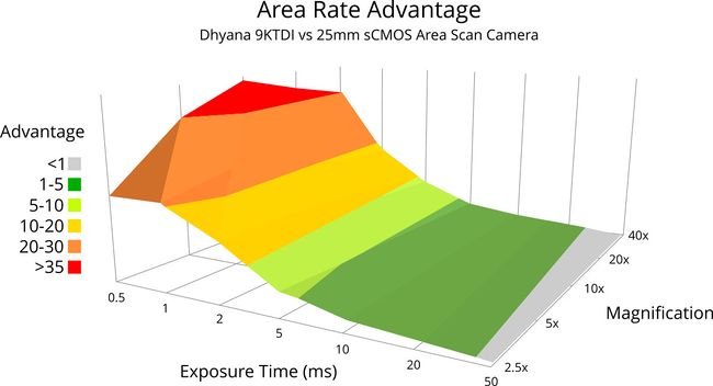
Figure 2. This plot assumes a Zaber X-ADR130 direct drive microscope stage with a 9 m/s2 acceleration and 50ms settling time.
The plot in figure 2 shows two important trends which determine the suitability of TDI imaging for your application.
- The relative performance advantage of TDI imaging vs stop-and-shoot imaging is greatest at magnifications between 5x and 20x. As the magnification increases, the number of discrete movements required for a stop-and-shoot strategy increases, resulting in settling time becoming a larger component of the overall scan time and limiting the maximum throughput. Higher magnifications also limit the maximum scanning speed of TDI imaging as magnifying the sample means more TDI slices are required to cover the sample area.
- The relative performance advantage of TDI imaging vs stop-and-shoot imaging is greatest at shorter exposure times. In low-light conditions requiring long exposures, it is faster to expose for a long duration, and then move quickly to the next image point rather than slowly scanning across the sample.
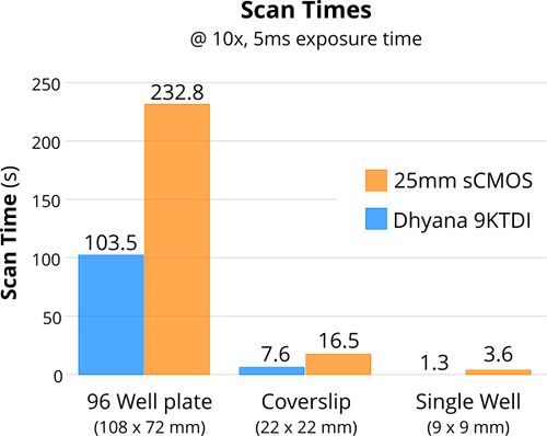
Figure 3. Comparison of TDI imaging vs stop-and-shoot imaging times to scan common imaging targets.
At 5 ms exposure and 10x magnification (Fig. 3) this TDI camera can offer a time savings of about 55% for many common High Content Screening (HCS) applications. At 1ms exposure the time saved is closer to 85%!
To maximize the advantage of a TDI camera, it is worth carefully considering what the shortest acceptable exposure time is. For example, a high content imaging system, particularly one where images will be analyzed by humans or go to publication will generally benefit from a longer exposure and lower gain. This will yield more detailed and attractive images with a better Signal to Noise Ratio (SNR). However, for diagnostics or experiments where a binary response is required and where image analysis will be performed automatically by software, a much shorter exposure time and higher gain may be acceptable. The images may not be as attractive and their SNR may be lower, but they will still be actionable and unambiguous.
Three Approaches for Setting up a TDI Scanning System
Capturing accurate, distortion-free images with a TDI camera requires the camera to be triggered every one pixel of distance. Triggering too fast will stretch the image, while triggering too slowly will compress it. There are three approaches to achieving the required timing.
Trigger-Free
The simplest implementation of a TDI scanning system is to move the stage at a predetermined velocity, and to set the camera to expect the sample to be moving at that velocity. Without a direct connection between the stage and the camera, real-time adjustment of the camera to compensate for fluctuations in velocity is not possible. In practice, the excellent velocity stability of Zaber’s linear motor direct drive stages means that trigger-free TDI implementations can work very well. The Position-Velocity-Time(PVT) tool in the free Zaber Launcher software package makes visualizing and setting up the appropriate motion sequences easy.
Direct Encoder Output
For applications demanding the tightest synchronization possible, some high-performance TDI cameras can accept direct quadrature encoder inputs. This enables the camera to directly measure the position of the stage and trigger at exactly one line per pixel of distance.
Quadrature outputs are available on Zaber direct drive stages including the ADR, LDA and LDM using an external X-MCC controller with the optional T8N1 feature set. Some TDI cameras may still require interpolation to support the full line rate of the camera. The encoder.2.out.interpolation setting on X-MCC controllers can adjust the number of quadrature counts generated on the interpolated analog encoder output per full cycle of the analog encoder. When combined with the camera’s onboard scaling, fine control over the camera’s triggering rate is possible.
IO Synchronization
Direct drive linear motor stages like Zaber’s X-LDA, X-ADR, and X-LDM can interface with TDI cameras via the digital output line on the stage. By setting up distance-based triggers on the stage, the XY stage can send pulses to the camera at a specific interval. In a typical implementation, a camera-based scaling will be required to run the camera at a higher frequency than the IO can support. Cameras may have line rates in excess of 500 kHz, while the maximum trigger rate of Zaber X-series devices is 8 kHz. The trigger UI in Zaber Launcher makes configuration distance-based triggers intuitive. An in-depth guide to setting up a TDI camera using IO triggering is provided below.
Detailed Instructions: How to Set Up a Zaber Nucleus Microscope for TDI
For this article, we selected a Tucsen Dyhana 9KTDI cooled sCMOS camera with a maximum trigger rate of 510 kHz. The Dyhana 9KTDI belongs to a new class of sCMOS TDI cameras which are capable of extremely high line rates with a total read noise penalty of 7 e- for the summed output of 256 reads. This was paired with a Nucleus® MVR automated inverted fluorescence microscope equipped with a Zaber X-ADR130B100B linear motor microscope stage. Zaber Linear motor stages use 1 nm resolution optical encoders giving them extremely accurate and repeatable positioning and encoder triggering, and enabling excellent velocity stability.
For more information on the specific system configuration used in this example, or to order yours today, visit our online configurator tool.
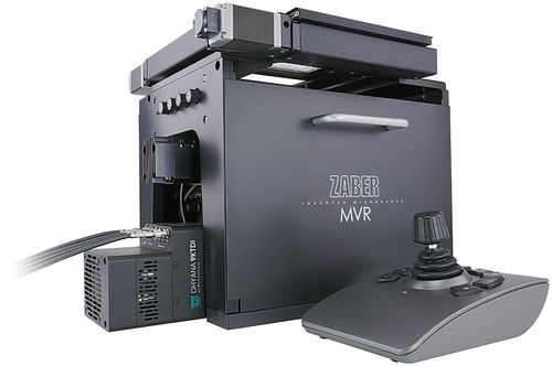
Figure 4. Dyhana 9KTDI sCMOS camera and Nucleus microscope.
Step 1. Camera Connection
For our testing we used the following hardware and software:
- Nucleus MVR Motorized inverted fluorescence microscope
- Zaber X-ADR130 microscope stage
- Tucsen Dyhana 9KTDI sCMOS camera
- Zaber D12 IO cable (included with X-ADR stages)
- Sparkfun BOB-12009 logic level shifter
- DfRobot DFR0140 5V / 3.3V USB power supply
- Tucsen HR10A-7P-4P trigger cable
- KAYA Komodo II FrameGrabber
- Tucsen M72x1 F-mount adapter ring
- Zaber MTC90x-F F-mount camera tube (Available upon request)
- Zaber Launcher stage configuration and control software
- KAYA VisionPoint frame grabber control and configuration software
- Tucsen Sample Pro camera control and configuration software
The Dyhana 9KTDI camera IO operates at a 3.3V logic level whereas the Zaber IO operates at 5 V. The BOB-12009 a basic, inexpensive logic level shifter (Fig. 6) is used in this example to provide low-latency voltage conversion for the signals. This is not an industrial grade component and is not recommended use in production systems or critical applications. To avoid damaging the camera, care should be taken to ensure the 5V and 3V3 pins are connected to the correct pins before turning on the power supply.
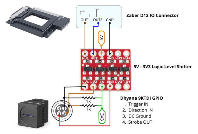
Figure 6. Schematic for connecting the BOB-12009 logic level shifter to the stage and camera.
The camera is connected using 4x CoaXPress 2.0 cables to the Komodo II frame grabber installed in a PCI-E 8x slot in your host PC. The Power Over CXP feature is not used by this camera, so no additional power connector is required for the frame grabber card. Once the camera is connected to the card and the power is plugged into the camera, wait for the light on the camera to turn green indicating that the connection with the frame grabber has been made.
Step 2. Trigger Rate Calculation
Synchronizing the triggering of the camera with the movement of the sample is critical to capturing clear, distortion free images. The trigger rate can be determined using the following formula will give the trigger rate in kHz: ƒ = (V•M)/p where V is the stage velocity in mm/s, M is the effective system magnification, and p is the pixel pitch in μm.
This calculation can easily be done using the downloadable spreadsheet available here.
This sheet (Fig. 6) can perform the “forward” calculation, which finds the required scan speed based on your desired exposure time, or the “reverse” calculation which returns a value for the required illuminator radiant flux setting based on a target scan speed and exposure time. Both calculations will return values for trigger encoder dist and the TriggerRescalerRate which are required for the trigger configuration in the next step.
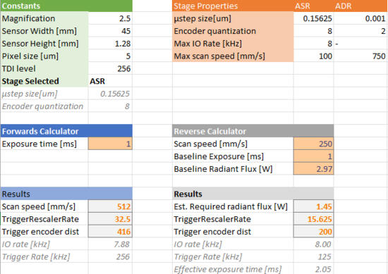
Figure 6. Trigger rate calculator.
Step 3. Zaber Stage Trigger Configuration
Using the trigger when encoder dist x command (FW 7.12 and above) on the Zaber X-ADR stage will fire the IO once the encoder measures that the stage has moved at least x units. The distance is specified in units of microsteps as calculated in step 2 above.
Note: Since Zaber stages process triggers on a 10 kHz tick, the calculator limits the trigger rate to 8 kHz to provide the maximum amount of velocity information while not missing any triggers.
trigger 1 when 1 encoder dist x
trigger 1 action a io set do 1 t
trigger 1 enable
To achieve the most efficient scan time, a “snake” pattern which alternates directions between scans will be used. It is necessary to change the camera TDI direction to match the stage direction at the end of every scan line. This is accomplished with the Camera Direction IO pin. When moving forward the pin should be set low, it should be set high when moving in the reverse direction. The step-over distance between long scanning passes should provide just enough overlap to assist with image stitching, but not so much that it adds many additional scanning passes. 5% is a good starting value.
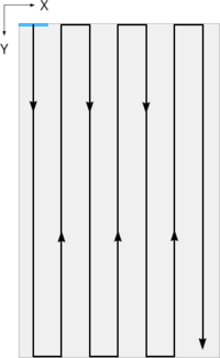
Figure 7. “Snake” pattern which reverses direction on alternating scan lines. A single field of view is indicated in blue.
The following set of triggers will set the TDI direction depending on the sign of the stage velocity.
trigger 2 when 1 vel >= 0
trigger 3 when 2 vel < 0
trigger 2 action a io set do 2 1
trigger 3 action a io set do 2 0
trigger 2 enable
trigger 3 enable
Step 4. Camera Trigger Setup
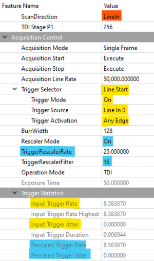
To achieve higher scanning speeds and maximize the potential of this imaging technique, it is necessary to increase the trigger rate beyond the 10 kHz tick of Zaber stages. The Dyhana 9KTDI camera includes a trigger rescaler which will multiply the received trigger frequency by a user-set value. This can be configured using Tucsen SamplePro or KAYA Vision Point software. The trigger setting used in this example are shown below:
- Direction
- Hardware triggering
- Trigger rescaler
 |
|
Figure 8. Tucsen SamplePro software camera configuration window
To test the settings, use the cycle command in Zaber Launcher (Fig. 9) to move your stage back and forward. Check that the Input Trigger Rate and Rescaled Trigger Rate matches those computed in step 2. These values will fluctuate when the stage is accelerating and decelerating, so the values will only be valid in the middle of travel once the stage is at a steady velocity.
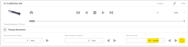
Figure 9. Enabling cyclic movement in Zaber Launcher to check triggering settings are correct
Step 5. Imaging Setup
Before imaging, the camera must be aligned to the scan direction. To do this, start the camera in “area scan” mode and loosen the locking ring on the Zaber MTC9X F-mount adapter. Focus the objective on the sample and rotate the camera so that the scan direction of the stage is perpendicular to the sensor. Adjust as required, then tighten the lock ring to fix the camera in the correct position.
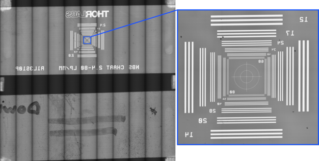
Figure 10. WSI image of two slides. 5x N-Achroplan, 100mm/s scan speed. Illuminated with MLR3B @ 3000K. No flatfield or focus corrections applied.
The VisionPoint software included with the frame grabber can stitch TDI images. In the frame grabber extended stream features / Image format control section, set the SegmentsPerBuffer to the length in pixels of one scan line and the Frames Per Stream to the number of scanned rows in your snake pattern.
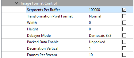
Figure 11. Vision Point software settings for Image Format Control
Step 6. Motion Control Setup
To take full advantage of the impressive capabilities of the latest sCMOS TDI cameras, you will require a motion control solution which is capable of rapid and stable movement and high-precision encoder output. The Zaber X-ADR130 XY stage used here is ideal for TDI scanning. The key advantages are:
- Excellent velocity stability. The X-ADR family’s integrated controller in combination with its high-thrust linear motors and low-drag crossed roller bearings delivers extremely smooth motion relative to lead screw driven stages.
- Interferometer-calibrated direct encoder. Every X-ADR stage is individually interferometer-calibrated. This minimizes encoder scale pitch errors which can cause the stage to misread its velocity, and dramatically improves the velocity resolution and repeatability
- High maximum speed and acceleration. With a peak speed of 750 mm/s and acceleration up to 20 m/s2 X-ADR stages excel at brightfield and transmitted imaging where illumination is not typically a limiting factor to imaging speed. At full speed and acceleration, an X-ADR stage can scan an entire 96-well plate at 2x magnification in under 2 seconds!
- Virtually unlimited service life. X-ADR stages are ideal for high-throughput applications and integration into OEM devices. Zaber’s linear motor stages have been tested in continuous 24/7 operation for over 1yr with no significant wear.
- Integrated controllers and drivers. Like all Zaber X-series motion control devices, X-ADR stages have integrated controllers and drivers which means your stages are ready to go straight out of the box. This greatly simplifies system setup.
To achieve the best performance, imaging should be done in the constant speed portion of the movement (Fig. 12) profile to avoid imaging artifacts caused by acceleration and deceleration.

Figure 12. Imaging should be carried out in the phase of the motion profile where the stage is moving at a constant speed which is highlighted in blue.
To achieve the best possible scanning times, the X-ADR’s upper axis should be used for the long scanning movements. The moving mass of the upper axis is lower which allows it to accelerate faster than the lower axis which must also carry the mass of the upper axis. The lower axis should perform the stepping movement between long scanning passes (Fig. 13, 14). At scanning speeds >100mm/s you should include a margin of overtravel distance beyond the sample (Fig. 13) so the stage can safely accelerate, decelerate and change direction completely outside of the sample area. Using Zaber Launcher, set your scan stage acceleration and deceleration as high as possible without stalling. This minimizes the distance traveled in the acceleration and deceleration phases. Setting the X-ADR’s scanning axis servo tuning to “stiff” and the stepping axis should be tuned to “smooth” in Zaber launcher is also recommended. These settings will maximize velocity stability and prevent unwanted oscillations as the scan proceeds.
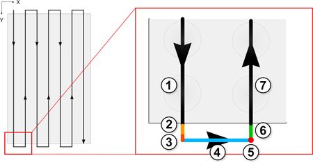
Figure 13. Phases of motion control. 1. Steady scanning speed, 2. Deceleration, 3. Stopped, 4. Step-over, 5. Readout direction change, 6. Acceleration, 7. Steady scanning speed. Overtravel included on scanning runs to ensure the scan is conducted entirely in the constant speed portion of the motion profile.
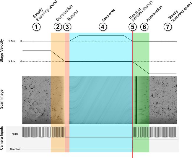
Figure 14. Stage velocity, camera inputs and resulting scan image as the scanning stage progresses through the scan and step-over sequence.
For large samples at higher magnifications it will be necessary to vary the focus in coordination with the XY stage to account for flatness errors in the sample. On Zaber Nucleus microscopes, this is done by passing a trigger signal to the X-LDA focus stage to sequentially step through a list of preloaded focus points.
Step 7. Automate Scanning and Imaging
To maximize imaging throughput, Zaber’s streaming feature can be used to load and run a preset motion sequence directly on the stage’s integrated controller. This eliminates the communication delays which are introduced by directing a stage’s motion from an external computer system. The use of streams for high-speed sample scanning is described in detail in this article: Maximizing your fluorescence imaging throughput with Zaber microscopes.
The Python code used in this example to scan a 96-well plate can be found here. This code computes the fastest way to traverse the sample given the dimensions and the accelerations of the X and Y axes. Based on these values, it will generate a stream which will execute the motion sequence. Once the stream generated by this script has been loaded onto the controller, it can be used for subsequent scans by calling the stored stream.
Configuring the camera and setting up image buffers is achieved using the Kaya KYFG API. It is available for python and C#. The examples used here provide a basic introduction to camera configuration and image acquisition with the Dyhana 9KTDI camera. A detailed explanation of the stitching and buffer management is beyond the scope of this article.
The example code available here performs the following basic actions:
- List available frame grabbers:
KYFG_Scan() - Open the selected frame grabber
KYFG_Open(grabberIndex) - Connect to camera 0
- Set desired camera settings using key-value pairs:
KYFG_SetCameraValueEnum_ByValueName(camHandleArray[grabberIndex][0], "PixelFormat", "Mono8") - Construct a stream buffer to contain the data.
KYFG_StreamCreate()- Assign a callback function to monitor it
- Allocate memory in an aligned_array to hold the frame buffer using
KYFG_BufferAnnounce()
- Start the camera, this will begin dumping data to the specified buffer.
KYFG_CameraStart() - Start the scan via ZML
- At the end of each line of the scan
- Read the image buffer out of memory
- Append it to the image taking into account that every other line will be vertically flipped due to the readout direction change
Once the camera and motion control hardware is connected and configured, and the software is set up, you are ready to scan.
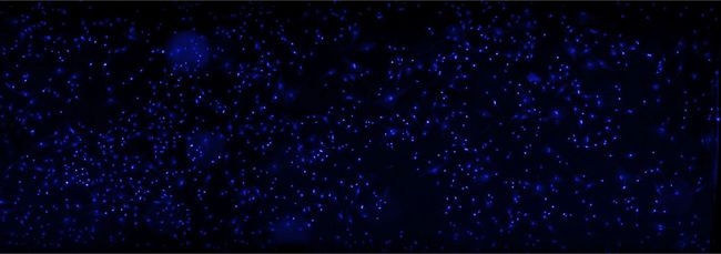
Figure 15. BFP scan of BPAE cells. Zeiss 10x EC Epiplan, 50mm/s, analog gain 8x, illumination @ 385nm with MLR3B
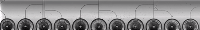
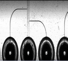
Figure 16. Microfluidic droplet generator. Zeiss 5x N-Achroplan, transmitted illumination with MLT100, scan time 1.5 seconds
TDI for Large Format Scanning Systems
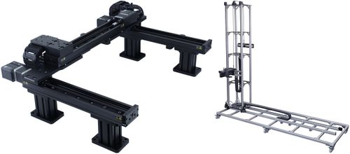
Figure 17. Example Zaber gantry systems for scanning large samples. Zaber’s gantry configurator tools make it easy to build and order custom gantry systems directly from our website.
In addition to microscope applications, TDI cameras can be used with precision motion control to image samples at very high resolution with conventional machine vision lenses. Zaber’s gantry systems (Fig. 17) are an ideal platform for applications such as large-format surface inspection or digital scanning of artwork in galleries.
The 45 mm line height of the Dyhana 9kTDI can also enable smaller samples to be captured in a single pass. This is particularly useful when scanning objects which are difficult to load in and out of a sample holder as it allows the sample holder to remain stationary while the camera sweeps across the sample. An example adapted from the method described above used the 9KTDI camera mounted to a Zaber X-LDM single axis linear motor stage (Fig. 18) to capture a high resolution scan of archival microfiche in a single pass (Fig 19).
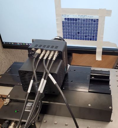
Figure 18. Camera mounting for microfiche scanning
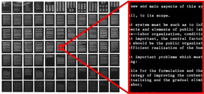
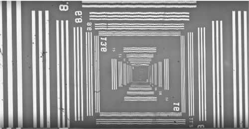
Figure 19. Complete scan of a microfiche in <450ms using an X-LDM210C and Schneider Optics Macro 80mm F5.6 lens.
Conclusion
TDI imaging can deliver an order of magnitude improvement in imaging speed compared to existing solutions! Recent developments in camera image sensor design have yielded a new class of low-noise sCMOS TDI cameras which bring the speed advantages of TDI imaging to the scientific world. Zaber’s linear motor X-ADR microscope stages combine extremely fast and repeatable motion, with precise encoders and velocity stability, making them ideal for TDI scanning systems. Combining a Zaber Nucleus inverted microscope with the X-ADR linear motor scanning stage and a Dyhana 9KTDI camera creates a modular imaging system capable of extremely high throughput.
Troubleshooting Tips
- Black bars in your image indicate that you are capturing a larger field of view than the microscope is able to image. Adjust the Width and Offset X to eliminate this.

- If your images look squashed or stretched along the scan axis this is indicative of a trigger rate mismatch. Check your trigger encoder dist and your
TriggerRescalerRate. Also check that the trigger rate is not set faster than the camera can run for your selected pixel format.
- High sensitivity cameras may deliver images which are too bright even at minimum gain and minimum illuminator power. This may be encountered when imaging with low-magnification objectives using in brightfield or transmitted illumination! Install a Neutral Density (ND) filter in your optical path to fix this.
- If your images are blurry along the scan direction but sharp in the transverse direction, then the trigger direction setting is likely backwards.

- If you see straight lines with a fuzzy / wavy appearance this is indicative of pixel-level shifts along the step axis. Try changing the the servo tuning to “smooth” which will make the control loop less aggressive
Jitter Issues
Jitter is the variance in the motion profile and imaging triggers from a perfectly constant delay and spacing between lines. Problems with jitter will cause the following artifacts:
- Exposure variance when the trigger rate is inconsistent
- Motion blur in cases where the distance moved between triggers is greater than a full pixel
Where the stage is slowing to a stop, you will see an increase in brightness as the trigger period slows. There will also be visible motion blurring in the output image (Fig. 14).
The total amount of jitter can be monitored using the InputTriggerJitter parameter on the camera, measured in %. Here are some representative values for Zaber stages which resulted in good quality images.
| XY Stage | Speed (mm/s) | InputTriggerJitter (%) |
|---|---|---|
| X-ASR120 | 50 | 1.5 |
| X-ADR130 | 100 | 1.0 |
Here are some sources of jitter to consider if you are encountering issues with your setup:
| Timing jitter | Motion jitter |
|---|---|
|
|