Magnetic Counterbalances for High Performance Vertical Stages
By Graham Kerr, Mechanical Engineering Team
Published on Mar. 11, 2022
Why use a counterbalance?
Linear motor stages deliver excellent precision, dynamic performance, and reliability. Zaber’s controllers combine this high performance with the easy-to-use Zaber ecosystem, providing seamless compatability with a wide range of motion control products and allowing even beginners to access nanometer level motion control in a matter of minutes.
Despite excellent performance, linear motor stages are not well suited for vertical applications without modification. Whereas fine-pitch leadscrew stages are inherently self-locking, the electromagnetic direct drive mechanism of linear motor stages means they will fall uncontrollably if power is lost while operating in a vertical orientation. Additionally, because linear motors cannot rely on mechanical drive reductions like screws or gearboxes, they must compensate for the full weight of a payload, resulting in significant heat generation.
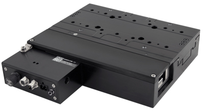
To make linear motor stages suitable for vertical applications, the addition of a counterbalance is required to compensate for the weight of the stage’s moving mass and payload. Usually it is ideal for the counterbalance’s force to perfectly balance the system’s weight, but sometimes the force is slightly offset if gentle upwards or downwards retraction is desired in the event of power loss.
Types of Counterbalances
The key parameters to consider when selecting a counterbalance are its:
- Impact on stage performance
- Travel Range
- Maximum supported load
- Lifetime
- Setup simplicity
- Ease of adjustability
- Cost
No solution can deliver all of these, so understanding the advantages and disadvantages of the four most common counterbalance designs (Table 1) is important when selecting a counterbalance for your application.
| Design | Counterweighted | Mechanical Spring | Pneumatic | Magnetic |
|---|---|---|---|---|
| Performance Impact | Significant | Small | Significant | Very Small |
| Travel Range | Many meters | <0.5m | <0.5m | <0.2m |
| Load Capacity | <200kg | <10kg | <20kg | <10kg |
| Lifetime | Good | Poor | Good | Unlimited |
| Setup Simplicity | Complex | Simple | Complex | Simple |
| Adjustability | Medium (change payload) | Difficult (change spring) | Easy (adjust regulator) | Fixed* (based on magnets) |
| Cost | $$ | $ | $$$$ | $$$ |
*Zaber is one of the few companies to offer an adjustable magnetic design.
Counterweighted Counterbalances
|
Pros:
|
Cons:
|
Counterbalances using a counterweight connected to the stage via a cable and pulleys are a common implementation for lower performance systems like belt driven stages. These designs are low cost and well suited for high loads and long travel ranges. However, the counterweight must match the weight of the stage’s moving mass and payload, inherently doubling the system’s total moving mass. This increased moving mass is not ideal for high performance linear motor applications because it significantly limits acceleration. Adjusting the counterweight to match a payload can also be tedious and is usually only done in fixed increments. For high throughput applications, the lifetime of the cable and other moving parts needs to be carefully considered.
Mechanical Spring Counterbalances
|
Pros:
|
Cons:
|
Counterbalances with mechanical springs are also common for a wide range of applications in the motion control industry. These designs are hard to beat from a cost and simplicity standpoint, but lifetime may be a concern depending on the application. The constant force springs required for a counterbalance are typically rated for 25000 cycles or less, which can be exceeded by linear motor stages in a matter of days. Typically, there is also no easy way to adjust the force output without replacing springs.
Pneumatic Counterbalances
|
Pros:
|
Cons:
|
Counterbalances with pneumatic cylinders are the most common design used for linear motor stages in industry. These counterbalances have medium load capacities and travel ranges, and are very user friendly; the lifting force can be finely adjusted in moments with the turn of a regulator knob. However, the requirement of a constaint air supply is a significant downside. Not only does this mean that an air supply needs to be routed to the stage, but also that the counterbalance is not failsafe; a loss of air pressure will result in the stage overheating and then falling. Sensors are also required to monitor for loss of air pressure and safely shut down the system, complicating setup.
For high performance linear motor applications there are additional considerations for pneumatic counterbalances. Conventional cylinders have sliding seals, limiting lifetime and creating friction. Friction is particularly problematic for high precision applications as described below. It’s possible to buy ultra-low friction glass on graphite cylinders which solve these problems, but they are expensive, not widely available, and have constant air leakage.
Magnetic Counterbalances
|
Pros:
|
Cons:
|
Counterbalances utilizing magnetic springs are ideal for high performance applications like linear motor stages. They are truly passive, requiring no air or power supply to provide force. The passive design makes these counterbalances ideal for applications with safety considerations or delicate payloads. They are also non-contact and have no moving parts, resulting in an inherently frictionless design with virtually unlimited lifetime.
The frictionless nature of magnetic counterbalances is particularly desirable for high precision applications. Friction is the primary factor increasing move times for small moves under a few microns, and settling time for larger moves. For small motions, a stage’s response is dictated primarily by the servo controller’s integral term, which takes additional time to wind up and overcome any friction present in the system. For this reason, lower friction also makes it much easier to optimize servo tuning across a range of move sizes. In addition to increasing move times, the directionality and stick-slip nature of friction can also limit positional repeatability.
It's worth noting that magnetic counterbalances are usually limited to lower load capacities and shorter travel ranges than other designs. However, most high precision linear motor applications already fall into this category, so these limitations aren’t nearly as much of a concern. For these types of applications, the performance benefits are invaluable.
Zaber’s Adjustable Magnetic Counterbalances
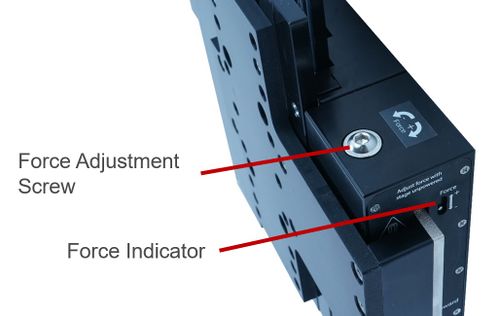
Nearly all magnetic counterbalances available in industry have fixed force outputs that are set at the factory, limiting the system to a very narrow payload range. To surpass this limitation, Zaber has developed a proprietary adjustable force magnetic counterbalance, allowing the force output to be finely tuned by a user in seconds. Not only does this allow a much wider range of payloads, but also means the counterbalance can be tuned to slightly rise or fall in the event of a power loss. This design provides the best of both worlds, combining the performance and reliability benefits of a magnetic counterbalance with the simple adjustability of a pneumatic counterbalance.
How it Works
The basic principle behind the adjustable magnetic counterbalance is remarkably simple. Consider two rectangular magnets spaced apart by distance D. Force FN is required to keep the magnets separated. Force FN is not suitable for lifting because it’s highly dependent on distance D.
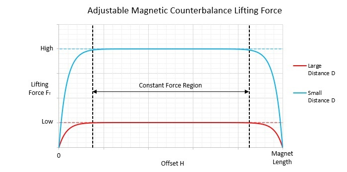
Now consider the case where the right magnet is also offset vertically by height H. An additional re-centering force, FT, is developed between the magnets. Force FT depends on distance D, but is constant for a large range of offset H. If bearings are used to compensate for force FN, force FT can be used to provide a constant lifting force. The lifting force can be adjusted with a mechanism that changes distance D.
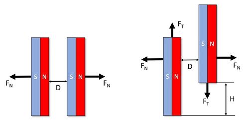
It is worth pointing out that when the magnets fully overlap or stop overlapping the lifting force drops off rapidly. However, there is a large range of constant force output in the middle which is suitable for use as a counterbalance. The interaction between distance D, offset H, and lifting force FT is shown below.
The simple theory behind this counterbalance ultimately translates into a highly reliable design. Some moving parts are needed to adjust distance D, but once the force is set the interaction is purely magnetic. Because most linear motor stages have oversized bearings to provide stiffness rather than load capacity, the normal force FN is not a concern.
Zaber’s Vertical Stage Offerings
Zaber offers adjustable magnetic counterbalances on it’s X-LDA-AEZ and X-LDM-AEZ series vertical stages. These ultra-precision linear motor stages feature low friction crossed-roller bearings, making them particularily well suited for the magnetic counterbalance design because there is no additional friction to degrade small step performance or repeatability. Due to the non-influencing nature of these counterbalances, accuracy, repeatability, and minimum incremental move specifications of the stages are unchanged by it’s addition.
The magnetic counterbalances are also an excellent complement for the reliability of the moving magnet track linear motor design. Even with the counterbalance, the linear bearings are the only moving parts on these stages.
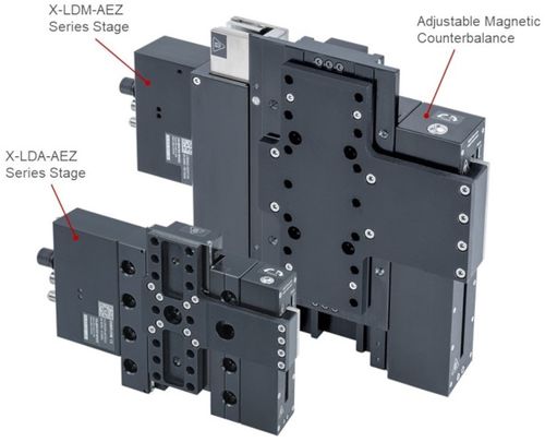
To view Zaber’s full lineup of vertical stages, visit the vertical stage product page.