Practical Guide: Machine Vision Cameras in Automated Microscopy
By Mike Fussell
Published on Apr. 28, 2025

Camera selection is a key decision when building an automated microscope system. While “scientific” cameras deliver excellent image quality, for many microscopy applications, machine vision (MV) cameras can deliver all the performance you need in a small and cost effective package. With so many cameras to choose from, how do you select a camera that strikes the perfect balance between a range of complex, and sometimes opposing performance criteria, and cost? Data sheets are a good starting point, but they don't tell the whole story. There is no substitute for a reliable, real-world reference.
This article introduces machine vision cameras, explores the differences between them and scientific cameras, and provides guidance on when MV cameras are worth considering for microscopy, and recommends a practical and economic camera as a starting point for your evaluation. Finally, this article reports the results of our first-hand experience testing three different machine vision camera brands that utilize the same image sensor.
What is a Machine Vision Camera?
Broadly speaking, machine vision cameras are small, uncooled CMOS cameras which are frequently used for industrial applications such as automated optical inspection and robot guidance. The enormous range of potential applications for MV cameras has led to the proliferation of camera and sensor options. The MV camera user is truly spoiled for choice, making it easy to select the camera with the best sensor size, resolution, and pixel architecture for your applications! Machine vision cameras are equipped with flexible IO for camera triggering and low-latency integration with third-party devices.
Finding Your Starting Point: The Baseline Camera Approach
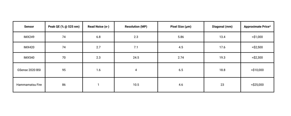
There are many things to consider when selecting a camera for an automated microscopy project. This article will explore some of those in more detail. While imaging performance specifications can help guide your selection, real-world testing of your system with an affordable, basic machine vision camera can save you time and money. Zaber’s CC01 camera is a Teledyne FLIR Blackfly monochrome machine vision camera which uses the popular Sony IMX249 2.3 MP CMOS image sensor. This camera has a good balance of sensitivity, read noise, resolution, pixel size, and field of view. Starting with a camera sensor like the IMX249 makes it easy to identify the areas which need to be improved to meet your performance targets, and by how much and what tradeoffs to other performance criteria are acceptable.


When to Use Machine Vision Cameras in Microscope
Situation #1: High Throughput Microscopy Applications with Automated Image Analysis Software
Machine vision cameras are ideally suited to applications which require high throughput, are not limited by low light, and where a human will not look at the raw data. Designers of systems where the acquisition and analysis of images will be automated must change their perspective of what makes a “good” image. Rather than optimizing for images that look good to humans, the goal should be to capture the “worst” quality images which can still yield unambiguous results as quickly as possible when analyzed by software. If you are using “AI”, a machine vision camera is worth considering.
A common example is imaging consumables to which fluorescent markers will hybridize to specific sites. To read these consumables, one must check each possible hybridization site for the presence or absence of a fluorescent signal.
Situation #2: When a Small Footprint is Important
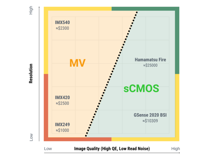
The small size, integration-friendly features and cost effectiveness of machine vision cameras make them an attractive option for OEM devices where minimizing the device footprint and retail price are important considerations. How are machine vision cameras different from scientific cameras? The distinction between machine vision and scientific cameras is not as clear as it once was. The term “Scientific CMOS” (sCMOS) was introduced in the mid 2010’s as advancements of CMOS image sensor technology lead to the development of the first CMOS image sensor cameras that could challenge the performance of then-dominant CCD image sensor technology. These new “sCMOS” sensors delivered improved performance relative to the CMOS sensors that were prevalent in MV cameras of the time. Since then, thanks to the rapid pace of CMOS image sensor development, the current generation of MV oriented CMOS sensors boast impressive performance. There are now many scientific cameras with MV sensors, and many MV cameras with scientific sensors.
Imaging Performance Differences
There are many great resources which provide much more in-depth analysis of camera imaging performance than this article, which will focus mainly on Quantum Efficiency and Read Noise as these are the most impactful differences between MV and sCMOS cameras lie. While sensor properties such as pixel size can have a big impact on imaging performance, both types of cameras are available with a wide range of pixel sizes.
Using your image analysis software as the judge of image quality is key. The difficulty in accurately displaying 12 and 14-bit monochrome images captured by modern cameras on a 8-bit RGB colour display can easily lead to images which may appear very poor to human viewers but having sufficient contrast and detail for image analysis software to make reliable decisions. This is particularly true of “AI” image analysis software.
Pro-tip: For in depth comparisons, Teledyne FLIR produces a handy Machine Vision Sensor Review listing over 100 sensors comparing their performance in easy-to-read charts.
Quantum Efficiency for Shorter Exposures
In microscopy, we’re mostly dealing with very low intensity signals. A camera with higher QE will allow for shorter exposures which will boost throughput compared to less sensitive cameras.
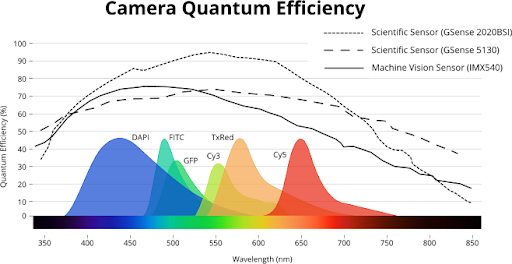
Quantum efficiency (QE) is the ratio of incoming photons that are converted into electrons of charge by the photodiodes of the image sensor. The QE curve of machine vision cameras is typically similar to that of a scientific camera, though some new sCMOS cameras can achieve quantum efficiencies of up to 95% (Fig. 1). One should not automatically assume that an sCMOS camera will have better quantum efficiency than a machine vision camera. Pixel size and architecture can have a big impact on QE, with larger pixels being more efficient than smaller ones, and back illuminated sensor architectures being much more efficient than front illuminated sensors. The Sony IMX 249 sensor delivers QE of 71 @525 nm, which is certainly on the higher end of machine vision cameras and higher than the IMX540 graphed below.

Read Noise and Low Intensity Signals
The uncertainty and variability in the sensor’s conversion of photodiode charge into a digital signal is called read noise. The higher the read noise, the harder it will be to reliably detect low intensity signals above that noise. The current generation of basic machine vision sensors have a read noise in the range of 3-4e-. The IMX249 has a read noise of 6.58 e-e putting it in the mid-range of advanced CMOS sensors. More advanced MV sensors offer read noise of about 2 e-, while some sCMOS sensors have special low-noise operating modes which allow them to achieve a read noise of below 1 e-.
Unlike machine vision cameras, most scientific cameras have active sensor cooling which helps to reduce image noise. Cooling a GPixel Gsense 2020BSI sensor from about 40॰C to 0॰C yields drop in read noise from 1.2 e- to 1.0 e-. The additional 0.2 e- improvement of the scientific camera may yield a noticeable improvement in image quality at ultra-short exposures and extremely weak signals, however for many applications where slightly longer exposures are possible, the improvement might not be noticeable.
Readout Differences and Higher Throughput
To maximize imaging throughput of industrial processes, many machine vision cameras use a global shutter readout architecture. Global shutter cameras read the entire sensor area out at once, whereas many scientific cameras use a rolling shutter architecture to read the sensor one line at a time. Global shutter sensors are ideal for imaging while moving, whereas rolling shutter cameras will produce skewed images of moving objects. Some low magnification, high throughput imaging applications can benefit from global shutter machine vision cameras as it can eliminate the need to fully stop and settle one one position before moving on to the next. When used correctly, global shutter cameras can deliver significant throughput improvements for automated imaging tasks.
Physical Characteristic Differences
The Size Difference
As MV cameras are commonly integrated into larger automated systems where component size matters, they are typically much smaller than scientific cameras. This can make them ideal for designers of benchtop instruments looking to keep device footprints to a minimum. A typical machine vision camera would be 29 mm x 29 mm x 40 mm, whereas scientific cameras are generally much larger. Scientific cameras 80 mm x 80 mm x 120 mm - or larger are common. The CC01 Teledyne FLIR Blackfly footprint is a very compact 29 mm × 29 mm × 30 mm.
Better Integration Features
To support system integration, MV cameras often have more IO lines and more IO functions than scientific cameras. These functions can be very useful when designing systems to achieve the highest throughput possible. For example, using IO on an XY stage to trigger image capture the instant the stage reaches its target settling threshold, then using the exposure active IO line on the camera to trigger the stage to move to the next position the instant image acquisition is complete creates an extremely low latency control loop capable of delivering significantly higher throughput than via software alone.
No Cooling Required
The sensor cooling systems of scientific cameras are a major contributor to their large size relative to MV cameras. These cooling systems can also introduce additional design considerations.The condensation and frost may form in the cooling systems on sCMOS cameras if they are installed in a humidified enclosure. The vents in the housing are also potential ingress points for liquid or particulate matter. Most machine vision cameras will be within their specified operating range in incubators with non-condensing humidity.
Price Difference
Machine vision cameras are generally much less expensive than scientific cameras. However, a direct comparison between the two types of cameras is of limited value. To support production quantities several orders of magnitude higher than scientific cameras, machine vision cameras make tradeoffs in image quality to keep their prices low. Meanwhile,scientific cameras are optimized to deliver superior imaging performance and their prices reflect that. The CC01 is quite affordable at under $1,000 USD. A typical sCMOS camera costs about $8000 USD. This price difference can have a major impact on the retail price of an OEM instrument!
An sCMOS camera might seem expensive compared to a machine vision camera, but if your application depends on maximizing imaging throughput of very low intensity signals, there is no substitute for sCMOS, so the lower price of a machine vision camera which would not deliver the required speed is of limited significance. Conversely, if your sample is sufficiently bright that reducing your exposure time will not significantly increase your throughput, or if throughput isn’t critical the additional performance of an sCMOS would not justify higher price.
Three Camera Brands Compared for Automated Inspection
Popular machine vision image sensors like those from Sony’s Global Shutter Pregius line have been integrated into cameras by many different manufacturers. So what are the differences between cameras with the same sensor from different manufacturers? To find out, Zaber tested machine vision cameras with the same image sensor from Teledyne FLIR, Basler, and Lucid Vision Labs.

Our Application
To build an accurate automated test system for Zaber’s microscope production line, we require a camera which will be connected to Nucleus microscopes and used to perform a series of measurements to verify the alignment of the optical path, and the intensity and uniformity of the illuminator. Just like fluorescence microscopy, this application requires a camera with high enough sensitivity and low enough read noise to make fast and accurate measurements across a range of wavelengths from 385 nm to 625 nm. The Image data will be analyzed by software tools.
Camera Selection
Our requirements for speed, ease of integration and “good enough” image quality lead us to select a machine vision camera over a scientific camera. In our application, illumination intensity does not limit the exposure speed, so the superior QE and read noise of an sCMOS camera would not deliver any meaningful improvement to the reliability of our analysis.
Our Production Engineering Team selected the IMX540 machine vision sensor as its large 19.3 mm diagonal sensor gives close full coverage of the maximum field of view of a C-Mount when mounted to a Zaber Nucleus microscope.
All three cameras share the same sensor, so their imaging performance can safely be assumed to be approximately equal. The key differentiators for our application were the alignment of sensor, the ease of Python API integration
Python API Compared
Basler and Lucid Vision Labs’ APIs were both easy to integrate and well documented. Our Production Engineering team had no issues integrating either of these into our automated test system. In regards to the Teledyne FLIR API, the latest versions of Python are not available on their website. We've been told customers can contact their support team who can provide a specified version.
Sensor Alignment Compared
The Sony IMX540 image sensor provides the full coverage of the viewable area on a Zaber Nucleus microscope with a C-Mount. This large size of the sensor means sensor alignment is critical. Even small alignment errors will result in many pixels of shift at the corners of the sensor.
Lucid Vision Labs’ active alignment manufacturing process delivered on its promise of excellent centering and angular alignment of the image sensor. The full area of the sensor was unobstructed and angular alignment of the sensor was very good.
The sensor alignment of the Teledyne FLIR camera was acceptable. The corners of the camera were slightly shaded as a result of the filter holder which seals dust out of the optical path and the sensor was tilted slightly.
On the Basler camera, surprisingly large areas of the corners of one side of the image were blocked by the filter holder that seals the optical path and the sensor was tilted by 3.7॰ (Fig. 2) relative to the base of the camera housing. Basler’s support team confirmed that this was inside their acceptable manufacturing tolerances. Basler recommended removal of the protective window as a potential solution, however this would void the warranty and would expose the internals of the camera to ingress of particulate matter. This solution did not address the underlying issue of the tilted sensor and the possibility that the next camera we purchased could be tilted equally far in the other direction.

This level of variability was deemed unacceptable for our application. While adjustment for tilt is possible on Zaber’s Nucleus microscope, the clipping of the corners would mean sacrificing effective sensor area with software adjustment (Fig. 3) to compensate for camera to camera variation. Losing this area would negate the value of a sensor that was chosen specifically to maximize the field of view as defects on the edges of the field of view could be missed.
Effective use of this model of Basler camera requires system builders to add angular adjustment to their camera mounts or add compensation features to their software. Lucid Vision Lab can provide an out of the box solution with no adjustment required.

Conclusion
For many automated microscopy applications, machine vision cameras offer compelling advantages in cost, size, and ease of integration. While specifications are helpful for guiding camera selection, practical testing with a baseline sensor like the Sony IMX249 2.3 MP is a practical and economic starting point for evaluating camera performance in your specific application. Remember that critical differences exist beyond the sensor; software usability and manufacturing quality, particularly precise sensor alignment, vary between manufacturers and demand careful evaluation for successful system design and reliable performance.