Driving Parallel Axes with Lockstep Movement
By Mike McDonald, Applications Engineering Team
Last updated on Jan. 12, 2021
Introduction
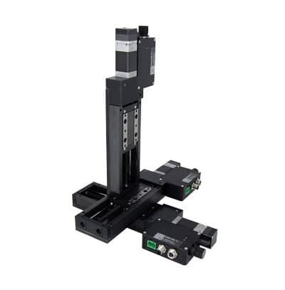
Many applications require multiple directions, or axes, of motion. Systems with one positioner per axis will be sufficient for many of these applications. Figure A shows a positioning system with three positioners. This is typically called an 'XYZ' or 'Cartesian' system. In this case, we refer to the lower horizontal positioner as moving in the X-axis. The Y-axis makes up the second horizontal axis, and the Z-axis defines vertical motion. When the Y- and Z-axes are relatively short, or when the load they carry is relatively light, a Cartesian system is a good solution.
Moment Loads
When the Y-axis is longer, the load on it applies a force at a distance, called a moment load, on the X-axis. Each stage has a rated tolerance for the maximum moment loading on it. If the rating is exceeded, there can be several effects on the performance of the system:
- Reduced lifetime from bearings and rails wearing more quickly
- Lowered maximum speed and thrust due to friction
- Loosening of pre-tuned components, reducing precision
Even if the rating is not exceeded, moment loads cause deflection which affects accuracy of the multi-axis system. The amount of deflection depends on the stiffness rating of the stage. Zaber's technical support can help you determine how much of a consideration the effects are for your application.
XY Gantry Systems
To reduce moment load, a second support on the X-axis can be added, parallel to the first. This will balance the moment load and greatly reduce the stiffness error. We typically call these kinds of solutions XY Gantry Systems. There are several possible configurations for gantries, which will best suit different applications. Zaber offers a number of starting configurations for customers to choose from and further refine.
Support Guide Gantries
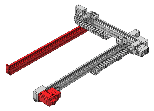
One option for an additional support is to use a support guide, which is a second X-axis stage without a motor or drive mechanism. Gantry systems that use support guides are simple and cost-effective solutions. The LC40 gantry systems are ideally suited for this configuration, as low cost support guide axes are available with a short lead time. Support guide versions of most of Zaber's linear stage series are available.
There are potential limitations to support-guide gantries. Support guides add friction to the system, reducing maximum speed and thrust. If there is only one support guide, the friction from it will act at a distance from the axis that is driven, which creates a twisting force. Similarly, accelerating the load will create an inertial force, which can create additional twist. The twist is similar to a moment load, and if the distance between the axes is large, it creates similar concerns. Using more than one support guide can help resolve this.
Physically Coupled Gantry Systems
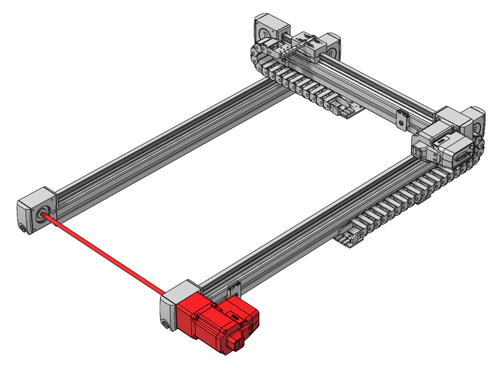
The issues related to passive guide gantries can be addressed by driving both parallel X-axes. With this solution, both the moment and frictional loads are balanced, so there are no longer any off-balanced loads. A key to having both axes driven is to ensure that they are driven synchronously. If they are not 'in-sync', then they will create a twist that can damage the system. One way to synchronize the axes is to physically couple them together.
To synchronize at the mechanical level, you must couple the drive mechanism of the axes together. Using mechanical coupling is the most robust method for pairing two axes, as there is a physical guarantee that they remain synchronized. A common method, used in the belt-driven LC40B Shaft Coupled gantries, is to use a coupling shaft to connect two pulleys, which each drive a belt. This solution ensures that both axes are being driven together, and it is suitable for many applications.
While it is the most robust form of synchronization, there are limitations to consider with this method:
- The power from one motor is being split between two axes, so the speed and thrust are less than in a non-gantry solution.
- Any position correction can only be applied to a single motor; the separate axes cannot make separate corrections to position error on each axis.
- Specific mechanics to fit the size of your system are required to match the distance between axes.
- The critical speed of the coupling shaft will limit how far apart two stages can be coupled. This is the speed where vibrations in the shaft will become unstable. Increasing the critical speed requires either a shorter coupling shaft, a larger diameter shaft, or a stabilizing bearing or bushing around the shaft mid-span.
- Shaft coupling adds an extra alignment requirement. In addition to being parallel and coplanar, the two devices must also be aligned so that their pulleys are approximately coaxial. Flexible couplings at each end can accommodate some misalignment.
- The clocking of the pulleys relative to each other also needs to be taken into consideration so that the two carriages are at approximately the same position.
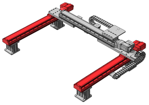
Synchronized Drive Gantry Systems
Instead of physically synchronizing the parallel axes, some drivers (including Zaber's X-MCC multi-axis controllers) are capable of synchronizing the motion of two or more separate motors. This allows multiple parallel axes to be driven together. The term for this feature with Zaber's controllers is 'lockstep' synchronization.
 |
 |
Power is multiplied with additional motors, allowing the gantry system to generate higher thrust and reach higher speeds than with a single motorized axis. This is especially useful for applications that require parallel vertical axes, where high thrust is needed to overcome gravity, or that have large payloads.
Fewer components are required to synchronize the axes, making digitally synchronized systems more flexible to set-up. It is also easy to mount multiple encoders with this solution, and the controller can drive each individually to better correct the error in the system. While digital synchronization isn't as robust against twisting as mechanical synchronization, incorporating encoder feedback in the system helps to catch twisting before it occurs.
Zaber Gantry Configurator Mounting and Alignment
While careful alignment is important during the assembly of any multi-axis system, it's doubly so for systems that use two parallel axes. In addition to ensuring that the X-, Y-, and Z-axes are perpendicular, you must also ensure the parallelism of the two X-axes. If the X-, Y-, and Z-axes aren't perpendicular, the coordinates you specify won't be accurate, but the system will move. If the two X-axes aren't parallel, there will be binding between the axes from the crossmember as they either narrow or widen, which can stall the movement. Following the steps below is one way to ensure the parallelism and perpendicularity of the axes. These offer general recommendations for assembly, but for Zaber LSQ, LRT, and LC40 gantry systems there are more detailed and specific instructions in the product manuals.
Step 1 - Mount Parallel Axes Loosely
Fasten the parallel axes to the mounting surface. Fasten one of the parallel axes firmly, but leave the fasteners on the second one loose. This loose mounting of one stage will make it easier to ensure parallelism later. Ensure spacing between the axes matches the mounting of the Y-axis, and also supports physical coupling of the drives if applicable.
Step 2 - Synchronize the Gantry Stages
After mounting, either home each axis individually using the home command for a drive synchronized gantry, or home the driven axis and manually move the other axis to the same position in travel. This step ensures that both stages are at their reference position as you mount the system together. You can adjust the position of one axis if an offset is required in order to square the system.
Step 3 - Couple the Movement
For a physically coupled gantry, connect the coupling mechanism. For a drive synchronized gantry, link the axes using the lockstep setup enable command. See the section "Enabling Lockstep and Synchronized Movement" for more details.
Step 4 - Connect the Crossmember
Next, mount the crossmember at 90° to the fixed axis. The crossmember may be one or more plates to which the Y-axis will mount, or the Y-axis stage may be directly mounted to the X-axes. Either way, use a square (or other alignment features) to ensure that the long edge of the crossmember is perpendicular to the base of the fixed first X-axis stage. Firmly fasten the crossmember down to this stage.
Step 5 - Tighten the System
With one side perpendicular, repeat the squaring process between the crossmember and the loosely mounted stage. Mount the stage loosely enough so that it can be adjusted until the stage and crossmember are perpendicular. Once perpendicular, firmly fasten the crossmember to the loosely-mounted stage.
Step 6 - Test the Movement
The two X-axis stages should now be parallel, but before firmly fastening the second axis, we can confirm they are parallel by moving the stages throughout the travel range. The parallel axes will then move together, and while they move, fasten the loosely mounted stage more firmly. Continue to move the stages together throughout the travel, tightening fasteners until all are tight. This step ensures that the system is not binding at any point in the travel.
Enabling Lockstep and Synchronized Movement
For drive-synchronized gantries, there is some additional setup required from software in order to pair the parallel axes, configure their behaviour, and move them.
Device 1 in this example is a multi-axis X-MCC controller set to communicate using the Zaber ASCII protocol, and the parallel axes are both connected to it. The command to enable lockstep is:
/1 lockstep 1 setup enable 1 2
Once enabled, the synchronized pair will stay locked together until the lockstep 1 setup disable command is sent. Even if the controller is powered off and on again, the axes will remain paired.
With lockstep enabled, individual axis movement commands will be rejected. Only lockstep movement commands are allowed for these axes, which address both axes and move both axes together. For example, to move both axes forward by 5000 microsteps, you would send the command:
/1 lockstep 1 move rel 5000
When you enable lockstep, you specify which axes you're including in the set. In the first command, we paired axes 1 and 2. The order in which these are specified is important because the first axis listed will be considered the primary axis. Any commands to move to an absolute position will use the primary axis position for the reference position.
So, if the current positions of the axes were 10000 for axis 1 and 12000 for axis 2, the command:
/1 lockstep 1 move abs 15000
moves both axes forward by 5000 microsteps to the positions 15000 and 17000 respectively. Thus, a certain difference will be maintained between the two positions, which is established based on the positions of the axes when you enabled the lockstep set. This difference is known as the offset value, and in the above example, it is 2000 microsteps.
Knowing the offset, the controller can enforce the travel limits of both axes. A movement command to a position within the travel range for the primary axis, but outside the second axis's travel range, would be rejected. Likewise, the limit sensors of both axes are respected. When the home command:
/1 lockstep 1 home
is sent, both axes will retract until the home sensor of either one is detected, then both will stop. The positions of the axes will then be updated such that the settings of the stage whose sensor was detected are followed, the offset value of the lockstep pair is applied, and the travel limits of both axes are enforced.
Twist Correction and Tolerance
While driving parallel motors in synchronized lockstep is a flexible and powerful solution, there is a limitation when compared to a physically coupled system. With physical coupling you have a guarantee that the stages will stay synchronized. You could run the system in open-loop without any issues. If you are relying on drive synchronization without encoders and one of the motors stalls, then the positions can become desynchronized and a twist in the system can develop. Twist in the system can result in incorrect positioning and high torsional loads on the system that can loosen the mechanical tuning or cause damage.
By adding encoders to each of the parallel axes, we can change from open-loop control to closed-loop control. This adds the same stall-detection capability that encoders add to any system. By being able to detect stall conditions on either axis, the system can stop both axes when only one stalls. This reduces the load that twist can exert on the system. Knowing the position of both axes, the controller can then move one axis independently to correct the positioning.
In addition to being able to detect stalls, a benefit of encoders is that the controller can quickly detect twist in the system during movement. The position of each axis is monitored, and if one gets too far ahead or behind the other, the system can stop and correct the difference. The tolerance for how much twist is acceptable in a system will vary from application to application, depending on the rigidity of the connection between the axes, the distance between them, the loading, the moment load rating and stiffness of the axes, and the speed at which the stages are being driven. The allowable twist can be adjusted by setting the lockstep tolerance using lockstep set tolerance. Gantry user manuals provide recommendations for maximum tolerance values based on travel distances that will help prevent physical damage.
XYZ Gantry Stages
For any of the above XY gantry systems, you can add on an additional vertical axis to make a XYZ gantry stage. One recommendation for this configuration is to use a multi-axis controller/driver that is capable of coordinating all of the motors together. For example, the X-MCC4 stepper motor controller is able to drive two parallel X-axes in a lockstep configuration, and synchronize these to draw circles, arcs, and lines with the Y and Z axes using Zaber's stream command set. The Zaber gantry configurator tool allows you to easily add on additional axes.
Conclusion
The best solution for a multi-axis system will depend on the requirements, such as loading, travel, precision, and budget. When moment loads become a large consideration, XY & XYZ gantry stages are often the best solution; there are several ways to implement them, and Zaber offers customizable systems to suit each implementation. Driving synchronized parallel axes using the lockstep feature is a flexible solution that enables a variety of configurations.
You can build your own system using Zaber's powerful gantry configuration tools. If you have questions about which is the best solution for your application, contact Zaber's Applications Team at contact@zaber.com to discuss your requirements. For more detail on the lockstep feature, please see the ASCII protocol manual.